| Workshop | Empennage | Wings | Fuselage | Contact |
| <-- November 2013 | January 2014 --> |
Chronological Updates, December, 2013
1 Dec 2013
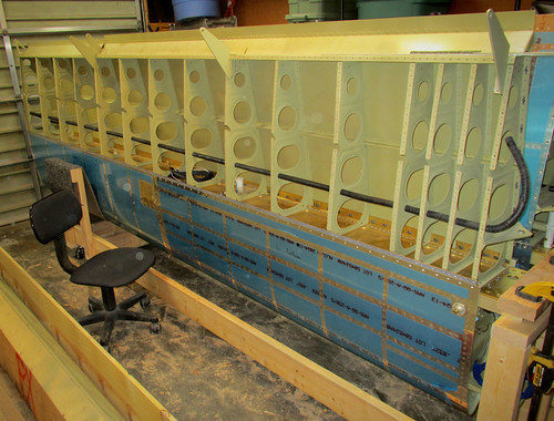
I wanted to see how many of the inboard bottom skin rivets I could do solo now that the more-difficult aft half was complete. They were all challenging, and it went really slowly because I had to check each rivet awkwardly with a mirror and flashlight, but it turns out I was able to get all of them done myself!
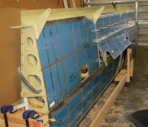
This felt like a real accomplishment for whatever reason. And for those of you who are counting, the 13,000th rivet in the plane is somewhere on that skin panel.
I went ahead and hung the outboard skin and cleco'd the aft half in place, as can be seen in the photo above. I won't be trying to solo those aft rivets, even though all of the outboard bays are wide, because the reach is too extreme for me to reliably rivet. I'll wait until Will can come back to start on those.
12 Dec 2013
Will came over after handball tonight and we started attacking the rivets on the right wing's outboard bottom skin. This piece is nicer than the inboard piece because all of the bays are wide, but it's twice as long so it's going to take awhile. Of the sixteen "panels" on the skin we were able to finish off three, starting at the aft center and working inboard.
It'll probably be another couple of visits from Will before the aft half of this skin piece is fully-riveted. I'm going to try to do most of the forward half myself again, though this one is more difficult because there are some bays that are quite a ways from the nearest access panel. Furthermore, for some reason the 14th (second-to-most-outboard) rib has inboard-facing flanges, meaning that it's not facing the closest access point for bucking (which would be through the outboard rib's lightening holes). Not a huge deal, just a pain. I might not be able to solo all of that; we'll see.
16 Dec 2013
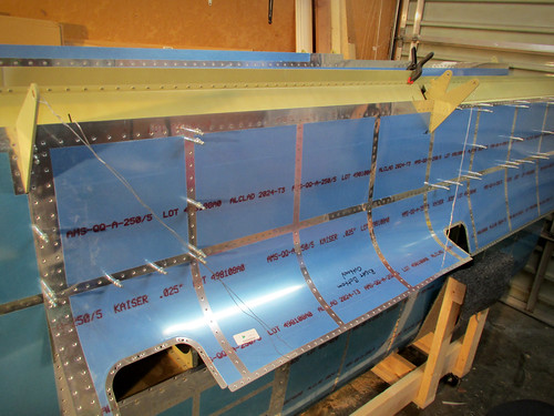
Will came over again and we worked on more of the skin rivets. We managed to get to the point where the inner 3/4 of the aft half of the skin was complete.
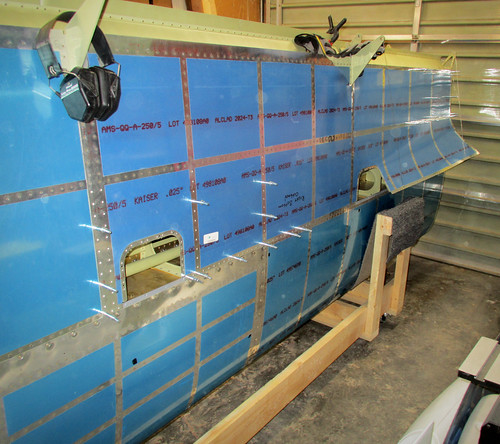
This allowed me to go ahead and cleco down the forward half of the skin on the inboard side and start working those rivets solo. It's a lot slower going by myself, so I only got one panel done in an hour. Seven of the 16 panels are now done on this piece as seen in the photo, above.
17 Dec 2013
When Will was last here he helped me muscle the left wing from the shop into the garage and place it into the wing cradle. This freed me up to attach the fuel tank, but before I could proceed I needed to shave down the edges of the Z-attach brackets so that they'd fit gracefully between the main spar bars.
I took a dremel to the brackets just like last time and took off a few milimeters from each side. Once that was done, I just carried the tank into the garage, lifted it into place, and hand-tightened a few of the bolts into place. This was infinitely easier this time around, mostly because I had done the dremel work ahead of time, but also because I didn't try to align the tank with the screw holes before getting the bolts in place. I did all of the bolts first, then the screw holes were where they should have been without any fuss.
All of the bolts are now in place and torqued to 25 inch-pounds [pardon the lame units]. I started attaching the AN509-8R8 screws, of which there are a lot, each with a bit of Boelube, but my arm got tired pretty quick so that part's not done. Also, there's no good way for me to reach the top-side screws because the other wing is in the way, so those screws may have to wait until I next have one of the wings off the cradle.
One of the issues I was worried about with attaching the fuel tank turned out to be a total non-issue: there is no interference between the outboard Z-attach bracket and the leading edge wire bundle.
I was very careful not to pinch the cable harness when I was raising the fuel tank into place, and once I had all the bolts tightened down, I was still able to push and pull the wire harness through the snap bushing with essentially no resistance, so there is no problem with the expanded tooling hole, larger snap bushing, and larger wire bundle than outlined in the plans. Whew.
18 Dec 2013
With the left wing now in the garage and with the fuel tank attached, I was anxious to get going on the aileron actuation hardware inside the main body. The section was pretty quick on the other wing and is nicely divisible into a bunch of small tasks, so I decided to take a stab at it during my lunch break today. First up was the aileron bellcrank weldment install.
This installation went really quick, probably because there's only five new parts including the bolt, nut, and washer. Total time spent: less than five minutes. So I decided to move on to the next bit, the torque tube.
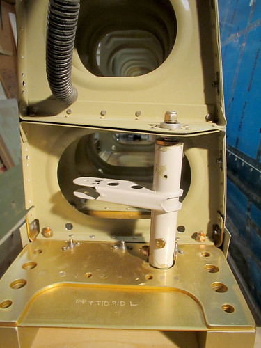
This section also goes pretty quickly because the bulk of the work on the torque tube had been done ages ago in pre-assembly. I got the tube threaded through the hole in the spar and the aft end put on to test the length. It looked like this:
The next step is to check the bolt holes that connect the aft torque tube weldment to the torque collar inside for misalignment. There had been none on the right wing, but this time there was a few millimeters of offset:
This isn't a huge deal; the plans specifically call it out as a possibility and give the cure: add a washer between the torque tube and the bearing to force the weldment in the correct direction. To do this, I had to remove the weldment from the bearing. It turned out to be really stuck in there. All the pulling in the world wasn't getting it free. So I tapped on the end of the threaded rod and this happened:
The bearing core popped right out of its housing! I didn't even know this was possible. Oddly, once the core was out of the housing, the core slipped off the threaded rod-end easily. No idea what that's all about. But I was left in the situation of having the bearing hardware separated, and the tolerances between the core and the housing were so tight that I couldn't get it back in there by hand.
I wasn't sure what the best plan would be so I consulted some friends that are mechanically-minded after work and got a range of responses that were all either recommending using an arbor press, using something that simulates and arbor press, or freeze the core and heat the housing and try to mash them together by hand. I don't have an arbor press and the whole tempreature manipulation angle seemed overly complicated for a first attempt, so I went to the hardware store and bought a machine screw, two washers, and a nut.
The basic idea here is to get a long 1/4" machine screw (this one was 3.5" long), a nut for it, a couple of washers, a socket that just fits inside the bearing housing (7/16"), and one that just barely doesn't fit inside the housing (9/16"). Both sockets need 1/4" arbors. The screw goes through the arbor end of the socket such that the head of the screw sits on the back face of the socket. Next, the bearing is pushed onto the screw until its outer race on one end is up against the open end of the socket. This is then placed on the bearing enclosure as shown in the left side of the picture above.
Initially, I just put some washers wide enough to be wider than the opening of the housing on the bottom, then threaded on the nut as shown in the center of the picture above. By tightening the nut, the washers sit flat against the bottom side of the housing. Since the top face of the nut is parallel to the bottom face of the screw, which is in turn parallel with the face of the socket and thus the bearing, as soon as the washers are pressed against the bottom of the housing, the bearing is kept in perfect alignment with the axis of the housing.
There is a slight bevel to the edges of the bearing and housing, so applying more pressure caused them to become co-axial, and then the bearing slid nicely into the housing with no trouble as the nut was tightened on the screw.
The only remaining problem was that the washers on the bottom made contact with the inner race of the bearing before the top part of the bearing was flush in the housing. So I took the nut and washers off and stuck a larger socket on the bottom which would only contact the housing and allow the bearing to be pushed farther down (see the right-hand photo). Once the bearing was at an appropriate depth, I released the pressure on the nut and removed all the hardware and it was just like new. Whew! Thanks to everyone who offered suggestions on how to get this done. I'm glad the solution didn't involve dry ice and blow torches.
With the bearing back where it should be, I re-assembled the torque tube in place, now with the spacer washer.
This introduced another problem, albeit much easier to solve. With the spacer washer in place, there is no longer any thread on the rod-end sticking out the end of the nyloc nut at the aft end of the torque tube (as seen in the picture, above). This will be easily solved by replacing the outer washer with a thinner one which I have in stock. However, at this point, I have put that nyloc on and taken it off several times as a result of all the bearing shenanigans. So I need to replace the nut and I'm not sure if I have any of those left. Not a big problem as it is easily accessible and this replacement can be done at any time.
Anyway, what should have been a quick 10 minute job turned into over an hour of work today but I learned some cool new techniques. I'll leave the pushrods for another day.
I wanted to see how many of the inboard bottom skin rivets I could do solo now that the more-difficult aft half was complete. They were all challenging, and it went really slowly because I had to check each rivet awkwardly with a mirror and flashlight, but it turns out I was able to get all of them done myself!
This felt like a real accomplishment for whatever reason. And for those of you who are counting, the 13,000th rivet in the plane is somewhere on that skin panel.
I went ahead and hung the outboard skin and cleco'd the aft half in place, as can be seen in the photo above. I won't be trying to solo those aft rivets, even though all of the outboard bays are wide, because the reach is too extreme for me to reliably rivet. I'll wait until Will can come back to start on those.
12 Dec 2013
Will came over after handball tonight and we started attacking the rivets on the right wing's outboard bottom skin. This piece is nicer than the inboard piece because all of the bays are wide, but it's twice as long so it's going to take awhile. Of the sixteen "panels" on the skin we were able to finish off three, starting at the aft center and working inboard.
It'll probably be another couple of visits from Will before the aft half of this skin piece is fully-riveted. I'm going to try to do most of the forward half myself again, though this one is more difficult because there are some bays that are quite a ways from the nearest access panel. Furthermore, for some reason the 14th (second-to-most-outboard) rib has inboard-facing flanges, meaning that it's not facing the closest access point for bucking (which would be through the outboard rib's lightening holes). Not a huge deal, just a pain. I might not be able to solo all of that; we'll see.
16 Dec 2013
Will came over again and we worked on more of the skin rivets. We managed to get to the point where the inner 3/4 of the aft half of the skin was complete.
This allowed me to go ahead and cleco down the forward half of the skin on the inboard side and start working those rivets solo. It's a lot slower going by myself, so I only got one panel done in an hour. Seven of the 16 panels are now done on this piece as seen in the photo, above.
17 Dec 2013
When Will was last here he helped me muscle the left wing from the shop into the garage and place it into the wing cradle. This freed me up to attach the fuel tank, but before I could proceed I needed to shave down the edges of the Z-attach brackets so that they'd fit gracefully between the main spar bars.
I took a dremel to the brackets just like last time and took off a few milimeters from each side. Once that was done, I just carried the tank into the garage, lifted it into place, and hand-tightened a few of the bolts into place. This was infinitely easier this time around, mostly because I had done the dremel work ahead of time, but also because I didn't try to align the tank with the screw holes before getting the bolts in place. I did all of the bolts first, then the screw holes were where they should have been without any fuss.
All of the bolts are now in place and torqued to 25 inch-pounds [pardon the lame units]. I started attaching the AN509-8R8 screws, of which there are a lot, each with a bit of Boelube, but my arm got tired pretty quick so that part's not done. Also, there's no good way for me to reach the top-side screws because the other wing is in the way, so those screws may have to wait until I next have one of the wings off the cradle.
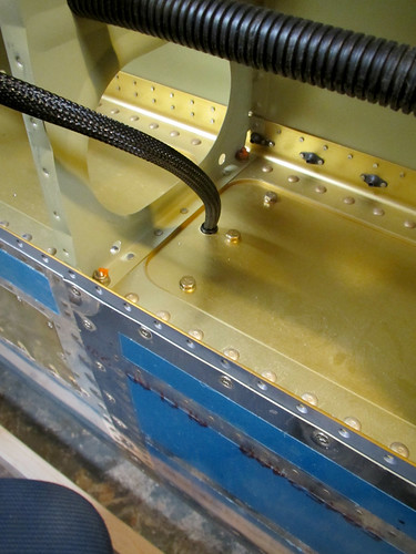
One of the issues I was worried about with attaching the fuel tank turned out to be a total non-issue: there is no interference between the outboard Z-attach bracket and the leading edge wire bundle.
I was very careful not to pinch the cable harness when I was raising the fuel tank into place, and once I had all the bolts tightened down, I was still able to push and pull the wire harness through the snap bushing with essentially no resistance, so there is no problem with the expanded tooling hole, larger snap bushing, and larger wire bundle than outlined in the plans. Whew.
18 Dec 2013
With the left wing now in the garage and with the fuel tank attached, I was anxious to get going on the aileron actuation hardware inside the main body. The section was pretty quick on the other wing and is nicely divisible into a bunch of small tasks, so I decided to take a stab at it during my lunch break today. First up was the aileron bellcrank weldment install.
This installation went really quick, probably because there's only five new parts including the bolt, nut, and washer. Total time spent: less than five minutes. So I decided to move on to the next bit, the torque tube.
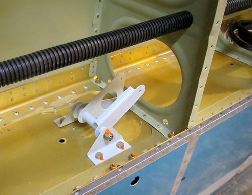
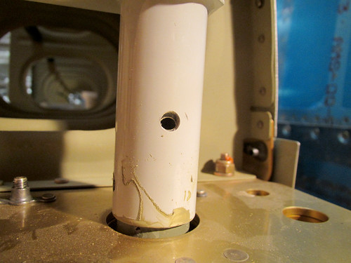
This section also goes pretty quickly because the bulk of the work on the torque tube had been done ages ago in pre-assembly. I got the tube threaded through the hole in the spar and the aft end put on to test the length. It looked like this:
The next step is to check the bolt holes that connect the aft torque tube weldment to the torque collar inside for misalignment. There had been none on the right wing, but this time there was a few millimeters of offset:
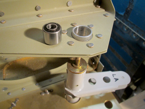
This isn't a huge deal; the plans specifically call it out as a possibility and give the cure: add a washer between the torque tube and the bearing to force the weldment in the correct direction. To do this, I had to remove the weldment from the bearing. It turned out to be really stuck in there. All the pulling in the world wasn't getting it free. So I tapped on the end of the threaded rod and this happened:
The bearing core popped right out of its housing! I didn't even know this was possible. Oddly, once the core was out of the housing, the core slipped off the threaded rod-end easily. No idea what that's all about. But I was left in the situation of having the bearing hardware separated, and the tolerances between the core and the housing were so tight that I couldn't get it back in there by hand.
I wasn't sure what the best plan would be so I consulted some friends that are mechanically-minded after work and got a range of responses that were all either recommending using an arbor press, using something that simulates and arbor press, or freeze the core and heat the housing and try to mash them together by hand. I don't have an arbor press and the whole tempreature manipulation angle seemed overly complicated for a first attempt, so I went to the hardware store and bought a machine screw, two washers, and a nut.
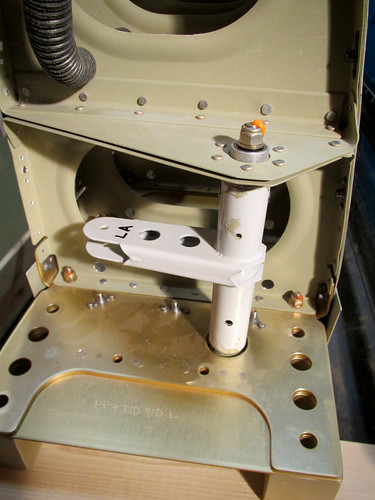
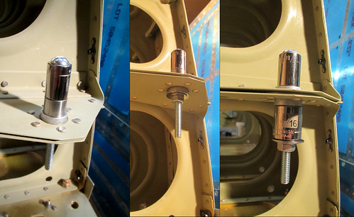
The basic idea here is to get a long 1/4" machine screw (this one was 3.5" long), a nut for it, a couple of washers, a socket that just fits inside the bearing housing (7/16"), and one that just barely doesn't fit inside the housing (9/16"). Both sockets need 1/4" arbors. The screw goes through the arbor end of the socket such that the head of the screw sits on the back face of the socket. Next, the bearing is pushed onto the screw until its outer race on one end is up against the open end of the socket. This is then placed on the bearing enclosure as shown in the left side of the picture above.
Initially, I just put some washers wide enough to be wider than the opening of the housing on the bottom, then threaded on the nut as shown in the center of the picture above. By tightening the nut, the washers sit flat against the bottom side of the housing. Since the top face of the nut is parallel to the bottom face of the screw, which is in turn parallel with the face of the socket and thus the bearing, as soon as the washers are pressed against the bottom of the housing, the bearing is kept in perfect alignment with the axis of the housing.
There is a slight bevel to the edges of the bearing and housing, so applying more pressure caused them to become co-axial, and then the bearing slid nicely into the housing with no trouble as the nut was tightened on the screw.
The only remaining problem was that the washers on the bottom made contact with the inner race of the bearing before the top part of the bearing was flush in the housing. So I took the nut and washers off and stuck a larger socket on the bottom which would only contact the housing and allow the bearing to be pushed farther down (see the right-hand photo). Once the bearing was at an appropriate depth, I released the pressure on the nut and removed all the hardware and it was just like new. Whew! Thanks to everyone who offered suggestions on how to get this done. I'm glad the solution didn't involve dry ice and blow torches.
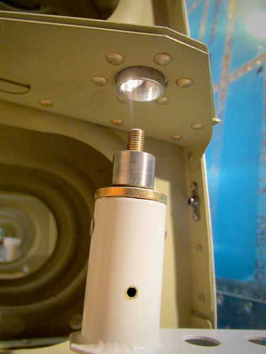
With the bearing back where it should be, I re-assembled the torque tube in place, now with the spacer washer.
This introduced another problem, albeit much easier to solve. With the spacer washer in place, there is no longer any thread on the rod-end sticking out the end of the nyloc nut at the aft end of the torque tube (as seen in the picture, above). This will be easily solved by replacing the outer washer with a thinner one which I have in stock. However, at this point, I have put that nyloc on and taken it off several times as a result of all the bearing shenanigans. So I need to replace the nut and I'm not sure if I have any of those left. Not a big problem as it is easily accessible and this replacement can be done at any time.
Anyway, what should have been a quick 10 minute job turned into over an hour of work today but I learned some cool new techniques. I'll leave the pushrods for another day.
| <-- November 2013 | January 2014 --> |