| Workshop | Empennage | Wings | Fuselage | Contact |
| <-- June 2013 | August 2013 --> |
Chronological Updates, July, 2013
20 July 2013
Here is the best picture ever.
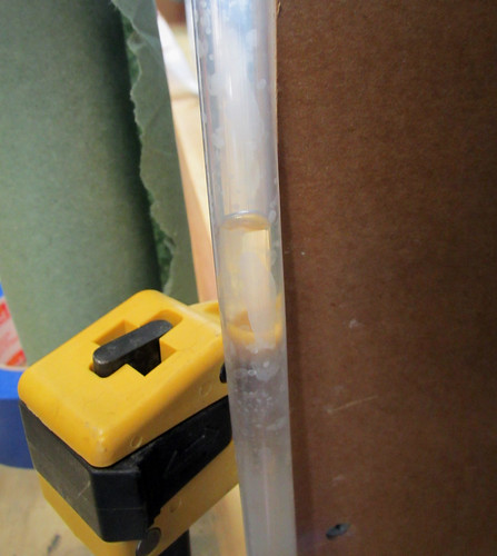
That is the water meniscus in my manometer monitoring air pressure in the right fuel tank. I have been fighting leaks in that tank for many months now. Finally, this time the tank held pressure for hours with no sign of a leak. So the sealing of the right fuel tank is COMPLETE! Yes!
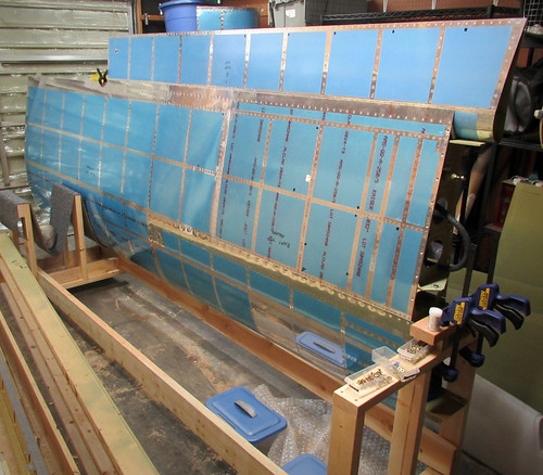
With that out of the way, I added the drain fitting, finger strainer, and fuel cap and set about masking off the skin and fittings so I could prime all of the external surfaces of the tank that aren't visible in the fully-assembled plane. Most people don't do this step, but I figured why not... I've spent so much time on these tanks I might as well add some primer, and it doesn't take much time. Here's one of the tanks all masked up:
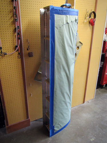
The weather turned rainy in the afternoon so I wasn't able to actually do the priming today, but soon!
21 July 2013
Today the weather was good so I pulled the fuel tanks out into the driveway and primed the necessary bits. Here's a picture of the results:
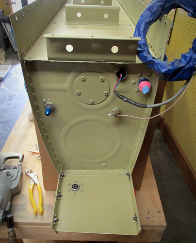
As you can see here, once the primer was in place I riveted on the torque tube bearing, shims, and nutplates on the forward attach bracket, rendering the fuel tank subassemblies complete! This is only slightly a lie; my cat seems to have run off with one of the bearings, so only the right tank is complete. The other tank is awaiting shipment of a new bearing before the last few rivets will be emplaced.
22 July 2013
No shortage of motivation to work on the plane these days, now that the leaky fuel tank bottleneck is gone... The next step was to attach the right fuel tank to the mostly-complete right wing. This proved to be very difficult to do. I was not able to push the fuel tank all the way up to the point where the skin holes would align with the nutplates on the main spar. It turns out the problem was that the Z-brackets on the aft bulkhead of the fuel tank were slightly too wide. Part of this was due to the primer I added, but even after sanding all of that off they were too wide. I ended up having to take a dremel to the brackets to narrow them by a couple milimeters each. I'd recommend for future builders to shave these down a bit during the fabrication process rather than having to do it in situ. Anyway, once I got the brackets narrowed the tank slid relatively easily into place. I had to give it a few light taps with the falt of my palm on the nose of the ribs to get the last centimeter or so, but no great force was required. Here's the right tank in place:
Initially I had placed some clecos into the skin holes prior to lining up the bolt holes in the spar and this proved to be the wrong way to go. The skin holes are a bit more forgiving to misalignment, whereas the bolt holes need pretty careful alignment. I had to take out the clecos and give the tank a small yank inboard to line the bolt holes up. The friction between the Z-brackets and the spar was enough to hold the tank up without any fasteners. Once the first bracket's bolts were loosely in place, I went ahead and put the rest of the bolts in hand-tight. The last bracket to get bolts was the inboard one, where the bolts go in from the opposite side. This one was slightly misaligned and I had to push a couple tapered drift pins in from the top (through the spar holes and then into the nutplates) in order to push the Z-bracket into place, then place a bolt into the middle bolt hole. This allowed the removal of the drift pins and replacement with the proper bolts.
With all the bolts in place, I went through and added the proper torque to each and placed a stripe of torque seal lacquer to each. With all the bolts done, I went to work with an electric screwdriver (strongly recommended) and added the dozens of screws needed to attach the skin to the spar. I added a smidge of Boelube to each screw and bolt to help cut the threads in the nutplates. I'm really excited to have the completed fuel tank in place on the right wing!
23 July 2013
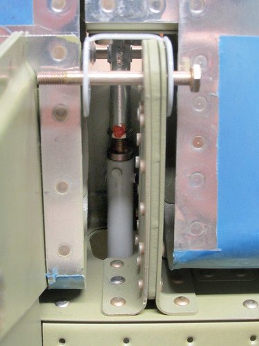
I had been waiting to install the aileron actuation hardware into the right wing so that the pushrod wouldn't be in the way of getting the fuel tank bolts torqued down. Now that the right fuel tank is installed on the wing, I went ahead and started getting the aileron actuation hardware finalized. Here's a picture of the torque tube installed in the wing root:
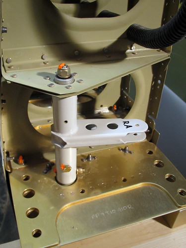
The secret to getting this in place is to jam the aft weldment way down on the torque tube, much farther than the point at which the through-holes line up. This allows the rod ends to go through the bearings at each end. Then, the aft weldment is pulled out until the through-holes line up and the weldment is bolted onto the tube as seen, above.
With the torque tube in place and the aileron bellcrank having already been installed earlier, it was time to install the pushrod between them and get its length set correctly. To do this, Van's offers a small jig in the kit that is attached to the bellcrank to hold it in its "neutral" position. A temporary 3/16" rod of some kind is needed to fit in the hole of the jig that lines up with the bolt hole for the smaller aileron pushrod. I used a drill bit, as seen below.
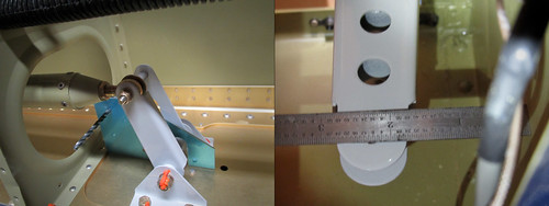
With one end of the pushrod attached to the bellcrank and the jig holding the bellcrank in its neutral position, The other end is attached to the aft end of the torque tube, and the separation between the inboard fuel tank rib and the forward end of the torque tube must be set to 2 and 9/32". This is measured to the center of the small bolt hole in the forward bellcrank weldment on the torque tube. Getting it just right required detaching the pushrod from the torque tube, loosening the jam nut, and turning the rod-end bearing in or out a few half turns. Once I had it just right, as seen in the picture above at right, I torqued down the jam nuts on both rod-end bearings, installed the bolts at each end, and put torque seal on everything. The main pushrod is installed!
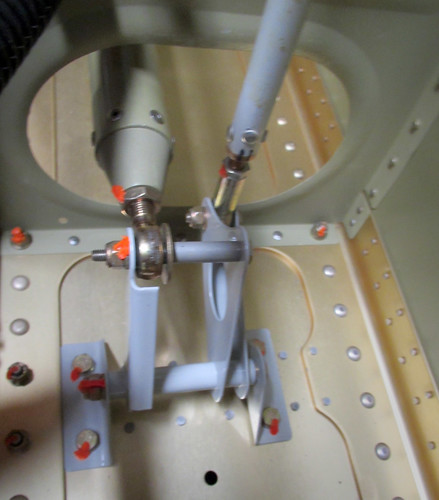
A similar system is used to correctly set the length of the smaller aileron pushrod that connects the bellcrank to the aileron itself. Here is a picture of the bellcrank with both pushrods installed:
And here is the other end of the aileron pushrod as seen from below:
It turned out that this pushrod I had at exactly the right length to keep the aileron lined up with the flap when the bellcrank was in its neutral position, so it needed no adjustment at all. I went ahead and torqued down the jam nuts on the pushrods but left both bolts at either end in a temporary configuration so that the aileron will be easy to remove.
Here is the best picture ever.
That is the water meniscus in my manometer monitoring air pressure in the right fuel tank. I have been fighting leaks in that tank for many months now. Finally, this time the tank held pressure for hours with no sign of a leak. So the sealing of the right fuel tank is COMPLETE! Yes!
With that out of the way, I added the drain fitting, finger strainer, and fuel cap and set about masking off the skin and fittings so I could prime all of the external surfaces of the tank that aren't visible in the fully-assembled plane. Most people don't do this step, but I figured why not... I've spent so much time on these tanks I might as well add some primer, and it doesn't take much time. Here's one of the tanks all masked up:
The weather turned rainy in the afternoon so I wasn't able to actually do the priming today, but soon!
21 July 2013
Today the weather was good so I pulled the fuel tanks out into the driveway and primed the necessary bits. Here's a picture of the results:
As you can see here, once the primer was in place I riveted on the torque tube bearing, shims, and nutplates on the forward attach bracket, rendering the fuel tank subassemblies complete! This is only slightly a lie; my cat seems to have run off with one of the bearings, so only the right tank is complete. The other tank is awaiting shipment of a new bearing before the last few rivets will be emplaced.
22 July 2013
No shortage of motivation to work on the plane these days, now that the leaky fuel tank bottleneck is gone... The next step was to attach the right fuel tank to the mostly-complete right wing. This proved to be very difficult to do. I was not able to push the fuel tank all the way up to the point where the skin holes would align with the nutplates on the main spar. It turns out the problem was that the Z-brackets on the aft bulkhead of the fuel tank were slightly too wide. Part of this was due to the primer I added, but even after sanding all of that off they were too wide. I ended up having to take a dremel to the brackets to narrow them by a couple milimeters each. I'd recommend for future builders to shave these down a bit during the fabrication process rather than having to do it in situ. Anyway, once I got the brackets narrowed the tank slid relatively easily into place. I had to give it a few light taps with the falt of my palm on the nose of the ribs to get the last centimeter or so, but no great force was required. Here's the right tank in place:
Initially I had placed some clecos into the skin holes prior to lining up the bolt holes in the spar and this proved to be the wrong way to go. The skin holes are a bit more forgiving to misalignment, whereas the bolt holes need pretty careful alignment. I had to take out the clecos and give the tank a small yank inboard to line the bolt holes up. The friction between the Z-brackets and the spar was enough to hold the tank up without any fasteners. Once the first bracket's bolts were loosely in place, I went ahead and put the rest of the bolts in hand-tight. The last bracket to get bolts was the inboard one, where the bolts go in from the opposite side. This one was slightly misaligned and I had to push a couple tapered drift pins in from the top (through the spar holes and then into the nutplates) in order to push the Z-bracket into place, then place a bolt into the middle bolt hole. This allowed the removal of the drift pins and replacement with the proper bolts.
With all the bolts in place, I went through and added the proper torque to each and placed a stripe of torque seal lacquer to each. With all the bolts done, I went to work with an electric screwdriver (strongly recommended) and added the dozens of screws needed to attach the skin to the spar. I added a smidge of Boelube to each screw and bolt to help cut the threads in the nutplates. I'm really excited to have the completed fuel tank in place on the right wing!
23 July 2013
I had been waiting to install the aileron actuation hardware into the right wing so that the pushrod wouldn't be in the way of getting the fuel tank bolts torqued down. Now that the right fuel tank is installed on the wing, I went ahead and started getting the aileron actuation hardware finalized. Here's a picture of the torque tube installed in the wing root:
The secret to getting this in place is to jam the aft weldment way down on the torque tube, much farther than the point at which the through-holes line up. This allows the rod ends to go through the bearings at each end. Then, the aft weldment is pulled out until the through-holes line up and the weldment is bolted onto the tube as seen, above.
With the torque tube in place and the aileron bellcrank having already been installed earlier, it was time to install the pushrod between them and get its length set correctly. To do this, Van's offers a small jig in the kit that is attached to the bellcrank to hold it in its "neutral" position. A temporary 3/16" rod of some kind is needed to fit in the hole of the jig that lines up with the bolt hole for the smaller aileron pushrod. I used a drill bit, as seen below.
With one end of the pushrod attached to the bellcrank and the jig holding the bellcrank in its neutral position, The other end is attached to the aft end of the torque tube, and the separation between the inboard fuel tank rib and the forward end of the torque tube must be set to 2 and 9/32". This is measured to the center of the small bolt hole in the forward bellcrank weldment on the torque tube. Getting it just right required detaching the pushrod from the torque tube, loosening the jam nut, and turning the rod-end bearing in or out a few half turns. Once I had it just right, as seen in the picture above at right, I torqued down the jam nuts on both rod-end bearings, installed the bolts at each end, and put torque seal on everything. The main pushrod is installed!
A similar system is used to correctly set the length of the smaller aileron pushrod that connects the bellcrank to the aileron itself. Here is a picture of the bellcrank with both pushrods installed:
And here is the other end of the aileron pushrod as seen from below:
It turned out that this pushrod I had at exactly the right length to keep the aileron lined up with the flap when the bellcrank was in its neutral position, so it needed no adjustment at all. I went ahead and torqued down the jam nuts on the pushrods but left both bolts at either end in a temporary configuration so that the aileron will be easy to remove.
| <-- June 2013 | August 2013 --> |