| Workshop | Empennage | Wings | Fuselage | Contact |
| <-- June 2011 | August 2011 --> |
Chronological Updates, July, 2011
8 Jul 2011
I put some bends in the fuel level sender probe that showed up earlier this week to test for fit. It seems to be perfect.
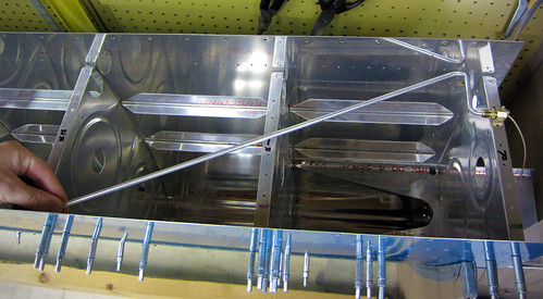
I am a little let down that the kit didn't include the nut and lockwasher that will be needed to secure the probe to the tank rib... but I can get that at the hardware store, I suppose.
16 Jul 2011
My locking fuel caps showed up awhile ago, but I seem to have neglected to talk about them here. They are a huge improvement over the stock fuel caps, even if you have no intention of locking your caps I suggest buying these. The mechanism and build quality are vastly superior in every way.
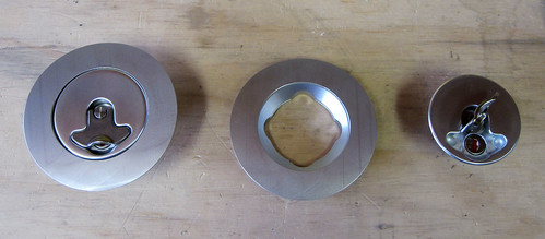
However, they do suffer from one of the same problems as the stock caps—the flanges are contoured to the wrong curvature for the RV-10 tank skin. When I hold my flange in place, the forward and aft edges are not flush at all.
I wasn't sure if the lack of flushness was entirely due to the part being the wrong shape, or if some of it was because the tank skin wasn't fully curved without the aft baffle in place. I went ahead and drilled the holes into the right-side fuel cap flange and cleco'd it into place along with all of the adjacent hardware (including the aft baffle) to see how bad the contour fit was.
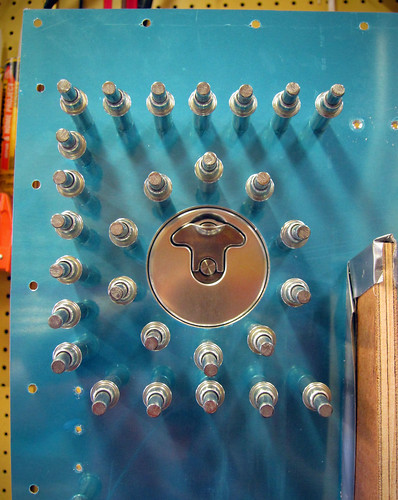
It was pretty terrible. The thin edges (forward and aft) were still standing off from the skin by many millimeters. What I needed to do was to sand down the outer contoured face of the flange to get some of the thickness off so that it would better match the skin. Unfortunately, I don't have the appropriate tool for that. In fact, I had marked several parts that needed tools I lacked for fabrication, including the fuel cap flanges, the fuel level sender access port covers, and several pieces of tube stock for aileron actuation. Last week I had a chance to run over to Pat Turner's shop with Bob and we did some quick fabrication work on these parts.
First, we cut the main aileron pushrods to length as well as the small steel pushrods that connect the aileron itself to the bellcrank in the wing. Next, we loaded the fuel cap flanges into a lathe and turned off about half the thickness of the highest parts.
The result was a flat section across the middle side-to-side, and a bit of contouring reamining on the forward and aft edges.
The next step will be to sand some curvature back into the central part of the flange with a belt sander, but I wanted to test fit these first to make sure it was helping. Turns out it needs a bit more taken off before the curvature is applied. But it is a lot better than it was!
The last thing we did at Pat's shop was to cut out some covers for the fuel level sender holes in the tanks. I had ordered the T-411 parts from Van's, but unfotunately they are for all Van's aircraft models except the RV-10. They advised me to send them back and just fabricate my own; I skipped the first part and just used the T-411s as stock for my custom ones. Having access to a CNC mill at Pat's shop, we cut out perfect 2.65" diameter circles.
Once the circles were cut, I clamped them into place on the fuel tank inboard rib and drilled out the screw holes.
Notice that in this picture the cover plate is inside the tank; this is just for ease of match-drilling the holes. The plate will be screwed onto the exterior of the tank during final assembly.
18 Jul 2011
For a change of pace, I did a bit of get-ahead work on the aileron actuation chapter of the plans. There are three main assemblies that need attention prior to a priming pass—the torque tubes, the main pushrods, and the bellcrank-to-aileron pushrods.
The main pushrods just require a cut-to-length and match drilling the end pieces on. I had Bob do the cuts for me on Pat's huge bandsaw. The match-drilling and deburring took no time at all.
The smaller pushrods require a length cut, which Bob took care of for me, and then some match-drilling that needs a V-block (which I don't currently have), so they're on hold.
Each of the two torque tubes is composed of two end weldments, two threaded inserts, and a collar connecting them. Bob cut the collar stock for me, and I match-drilled and riveted the threaded ends into the weldments.
For some reason, the threaded ends get riveted in prior to priming as per the plans, and only the forward ends and the collar get primed (??). Not sure if that's an omission in the plans or if there is a good reason.
25 Jul 2011
I did a couple of minor things today. First I deburred and dimpled the last of the aileron skins so they are all done now and ready for final assembly.
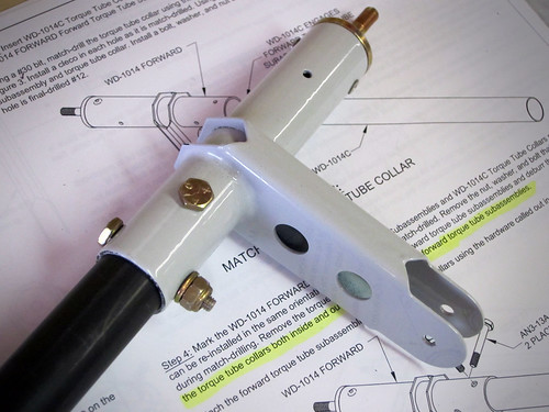
Next, I picked up my cut torque tube collars and replacement fuel sender access panel cover (I had mis-drilled one of the ones I made before) from Bob. When I got home from work, I set to work continuing the aileron actuation chapter by putting together the forward torque tube assemblies. The first step here was to match drill the weldments into the torque tube collars.
This went without a hitch. The next step was to drill #12 the matched holes out so that a AN3 bolt will fit through. On one of the torque tubes, this went flawlessly:
Unfortunately, on the other one, I managed to get the drill out of alignment somehow and made a huge oval out of one of the holes in both the collar and the weldment. So that piece is ruined. At a minimum, I'll need to order a new weldment ($60) and a new piece of the pipe ($20). If I can't get the pop rivets out cleanly, I'll also need a new end cap ($8). With shipping, I'm looking at about $100 for a botched drill job. Ouch. Probably the most expensive mistake in the plane thus far.
I put some bends in the fuel level sender probe that showed up earlier this week to test for fit. It seems to be perfect.
I am a little let down that the kit didn't include the nut and lockwasher that will be needed to secure the probe to the tank rib... but I can get that at the hardware store, I suppose.
16 Jul 2011
My locking fuel caps showed up awhile ago, but I seem to have neglected to talk about them here. They are a huge improvement over the stock fuel caps, even if you have no intention of locking your caps I suggest buying these. The mechanism and build quality are vastly superior in every way.
However, they do suffer from one of the same problems as the stock caps—the flanges are contoured to the wrong curvature for the RV-10 tank skin. When I hold my flange in place, the forward and aft edges are not flush at all.
I wasn't sure if the lack of flushness was entirely due to the part being the wrong shape, or if some of it was because the tank skin wasn't fully curved without the aft baffle in place. I went ahead and drilled the holes into the right-side fuel cap flange and cleco'd it into place along with all of the adjacent hardware (including the aft baffle) to see how bad the contour fit was.
It was pretty terrible. The thin edges (forward and aft) were still standing off from the skin by many millimeters. What I needed to do was to sand down the outer contoured face of the flange to get some of the thickness off so that it would better match the skin. Unfortunately, I don't have the appropriate tool for that. In fact, I had marked several parts that needed tools I lacked for fabrication, including the fuel cap flanges, the fuel level sender access port covers, and several pieces of tube stock for aileron actuation. Last week I had a chance to run over to Pat Turner's shop with Bob and we did some quick fabrication work on these parts.
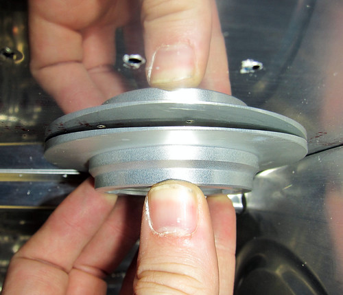
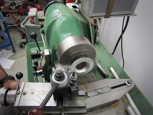
First, we cut the main aileron pushrods to length as well as the small steel pushrods that connect the aileron itself to the bellcrank in the wing. Next, we loaded the fuel cap flanges into a lathe and turned off about half the thickness of the highest parts.
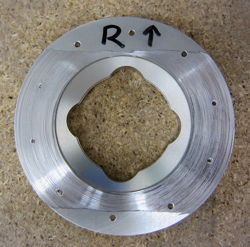
The result was a flat section across the middle side-to-side, and a bit of contouring reamining on the forward and aft edges.
The next step will be to sand some curvature back into the central part of the flange with a belt sander, but I wanted to test fit these first to make sure it was helping. Turns out it needs a bit more taken off before the curvature is applied. But it is a lot better than it was!
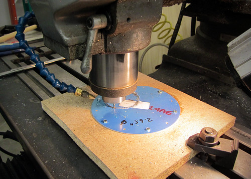
The last thing we did at Pat's shop was to cut out some covers for the fuel level sender holes in the tanks. I had ordered the T-411 parts from Van's, but unfotunately they are for all Van's aircraft models except the RV-10. They advised me to send them back and just fabricate my own; I skipped the first part and just used the T-411s as stock for my custom ones. Having access to a CNC mill at Pat's shop, we cut out perfect 2.65" diameter circles.
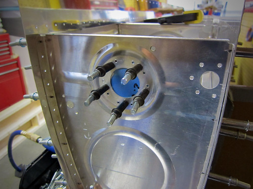
Once the circles were cut, I clamped them into place on the fuel tank inboard rib and drilled out the screw holes.
Notice that in this picture the cover plate is inside the tank; this is just for ease of match-drilling the holes. The plate will be screwed onto the exterior of the tank during final assembly.
18 Jul 2011
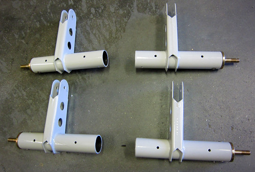
For a change of pace, I did a bit of get-ahead work on the aileron actuation chapter of the plans. There are three main assemblies that need attention prior to a priming pass—the torque tubes, the main pushrods, and the bellcrank-to-aileron pushrods.
The main pushrods just require a cut-to-length and match drilling the end pieces on. I had Bob do the cuts for me on Pat's huge bandsaw. The match-drilling and deburring took no time at all.
The smaller pushrods require a length cut, which Bob took care of for me, and then some match-drilling that needs a V-block (which I don't currently have), so they're on hold.
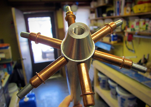
Each of the two torque tubes is composed of two end weldments, two threaded inserts, and a collar connecting them. Bob cut the collar stock for me, and I match-drilled and riveted the threaded ends into the weldments.
For some reason, the threaded ends get riveted in prior to priming as per the plans, and only the forward ends and the collar get primed (??). Not sure if that's an omission in the plans or if there is a good reason.
25 Jul 2011
I did a couple of minor things today. First I deburred and dimpled the last of the aileron skins so they are all done now and ready for final assembly.
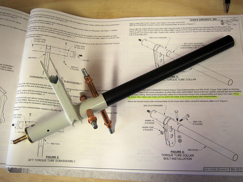
Next, I picked up my cut torque tube collars and replacement fuel sender access panel cover (I had mis-drilled one of the ones I made before) from Bob. When I got home from work, I set to work continuing the aileron actuation chapter by putting together the forward torque tube assemblies. The first step here was to match drill the weldments into the torque tube collars.
This went without a hitch. The next step was to drill #12 the matched holes out so that a AN3 bolt will fit through. On one of the torque tubes, this went flawlessly:
Unfortunately, on the other one, I managed to get the drill out of alignment somehow and made a huge oval out of one of the holes in both the collar and the weldment. So that piece is ruined. At a minimum, I'll need to order a new weldment ($60) and a new piece of the pipe ($20). If I can't get the pop rivets out cleanly, I'll also need a new end cap ($8). With shipping, I'm looking at about $100 for a botched drill job. Ouch. Probably the most expensive mistake in the plane thus far.
| <-- June 2011 | August 2011 --> |