| Workshop | Empennage | Wings | Fuselage | Contact |
| <-- July 2010 | September 2010 --> |
Chronological Updates, August, 2010
14 Aug 2010
It's been awhile; I've been out of town for work, but I'm back now and spent a quick hour today getting some tasks ready for the main event of the empennage attach chapter. Namely, the day I'll fully attach the entire tail section of the aircraft in my driveway.
While I was gone, I looked through the plans and made a list of small tasks that needed to be taken care of before I could do the actual attachment, and set about doing some of those things today. First off, the elevator trim bracket was a bit long on the aft edge for the holes in the aft deck to line up with the nutplates in the bracket now that I've bolted and riveted the aft end of the tailcone together. It was only long by about 1/16", so I just took the scotchbrite wheel to that edge and now it fits like a champ.
Next, I checked my hardware bins and made sure I had the necessary bolts and washers for the actual attachment. No problems there.
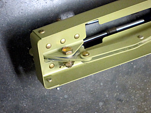
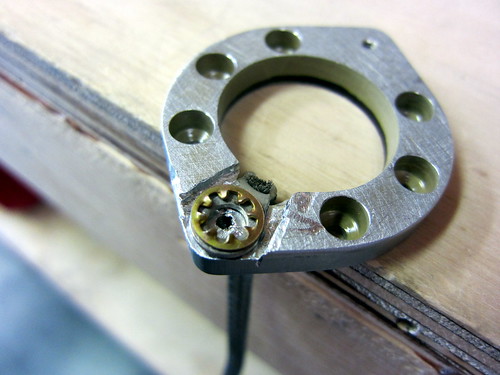
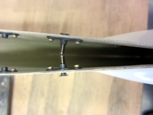
Finally, I addressed the problem I had earlier with the elevator trim bellcrank mechanism binding rather than rotating freely. I measured the gap as-built and the thickness of the bellcrank plate plus the two washers was too large by 0.02". Not much, but enough to make it too tight. The suggested fix from the forums was to grind down the washers using a belt sander (which I don't have). Instead, I just took the scotchbrite wheel to the sides of the bellcrank plate and took off the primer and a bit of the metal. It did this slowly and in many iterations to ensure that I wasn't taking off too much. Each time, I'd load the parts back up and rotate it a few times and the washers would leave marks where the plate was still too thick. Once I got the right amount off, it spins freely. The change in thickness is not visually perceptible, so I'm not concerned about compromosing the structural integrity of the plate. Here's a picture of the bellcrank mechanism from the bottom after everything was fully assembled.
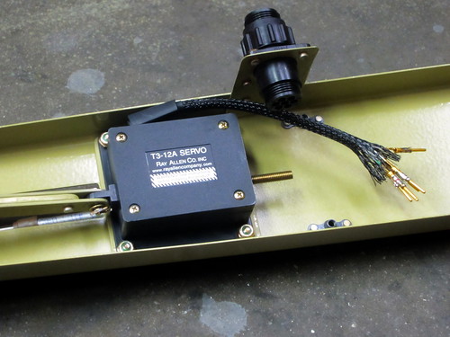
Of course, this also means that I finally installed the T3-12A servo in its spot just aft of the bellcrank. I haven't connected the wires to the CPC on the drop plate yet because I want to put a strain relief cap on it but I don't have one in stock. Time for a mouser.com order.
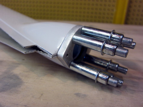
And here's the final view of the forward end of the trim push-pull cables installed onto the bellcrank.
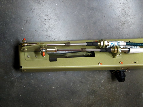
It was really hard getting the right-side cable through the mounting bracket; for some reason that hole seems to be just a fraction smaller than the other. But I did manage to get it through and they look great. I'm thinking I should take off those labels that read "Not for use in aircraft" in bright red letters... (a note to those who are concerned by this, it's a liability thing... the cables are perfectly acceptable for use in aircraft and are actually supplied by the kit manufacturer).
The bellcrank is shown in the full nose-down trim position here, with the cables fully extended on this end.
16 Aug 2010
I did a couple more mini-tasks getting ready for the big empennage attach day in the ill-defined future, namely making the elevator bellcrank angle template out of some foam board and getting the forward end of the elevator trim push-pull cables tightened down at the right length. The only remaining tasks here are to make the 2x4 block for squaring the horizontal stabilier and to put the rod-end bearings into the rudder. One those are done, I'll be on hold with empennage attach until I have a full day with a helper that I can spend doing the rest of the chapter. It's possible this will occur this coming Sunday, or perhaps it's weeks away. So I moved on to starting the empennage fairings chapter in the meantime.
The first fairings to work on in the empennage fairings chapter are the elevator tips. These, along with the upper rudder fairing, are the easiest because they don't require significant modification and they don't need to be removable. The flange on the first elevator fairing I grabbed was already at (or slightly smaller than) the recommended half-inch in width, so no trimming was necessary there. I took a razor to the flange inset corner and cleaned out some small chaff. Then I took a dremel cutoff wheel to the aft end of the flange to remove a small chunk in order to make room for the elevator trailing edge extrusion piece. Cutting the fiberglass with the cutoff wheel was surprisingly easy.
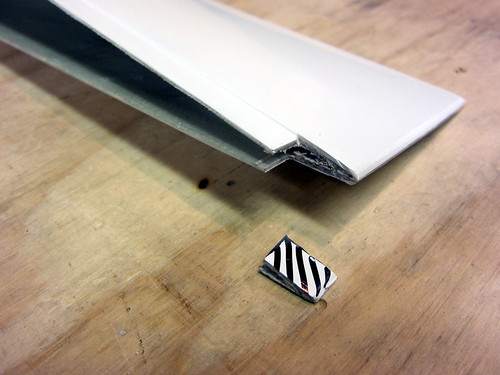
With that cut made, the fairing slipped very nicely into my left elevator. There was no interference from the static wick attachment platenuts. There was, however, a huge gap between the fairing and the skin except right at the forward and aft ends.
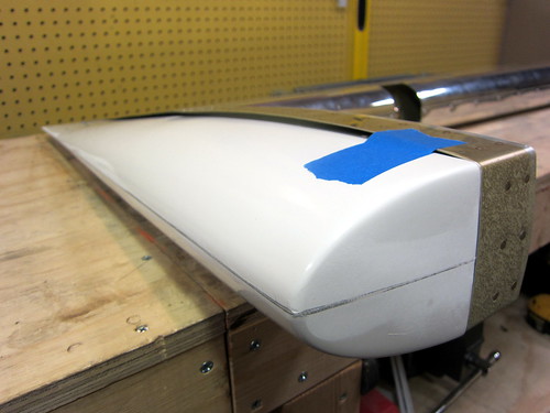
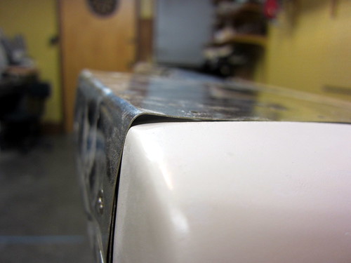
I guessed that when drilled and cleco'd together, this gap would vanish. I was right. It's fortunate that there was no gap at the forward end, where the drilling begins. As I drilled and cleco'd one hole, it would cinch up the gap for the next drilling, and so-on. Here's the result after all the match drilling.
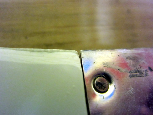
One problem that did not go away with drilling and clecoing the fairing to the skin, however, was that the fairing was about 1/16" too long.
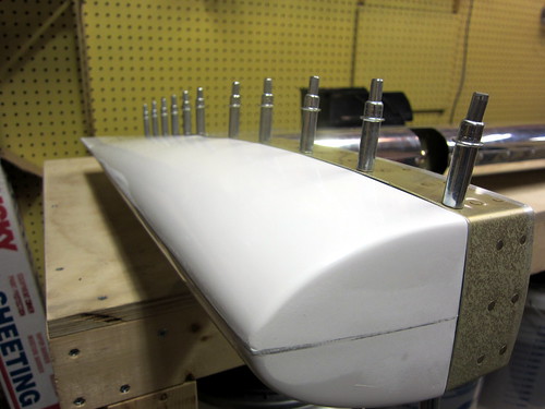
I put a sanding drum in the dremel and trimmed down the offending corner until they were reasonably flush. I'll eventually be coating this entire joint up with filler and sanding it all smooth so it should look like one continuous piece.
The last thing I did tonight was take the fairing back off the left elevator and start dimpling the holes. For the aft-most holes, I had to use the pop-rivet dimple die set, so I just used it for all holes. I wasn't able to get the forward-most hole on each side without removing the lead counterweight, which I put off for another day. So 20 of the 22 holes are now dimpled.
The fairing showed considerable spall from the drilling, though only in the outer finish coating. The hole in the underlying fiberglass looked very good.
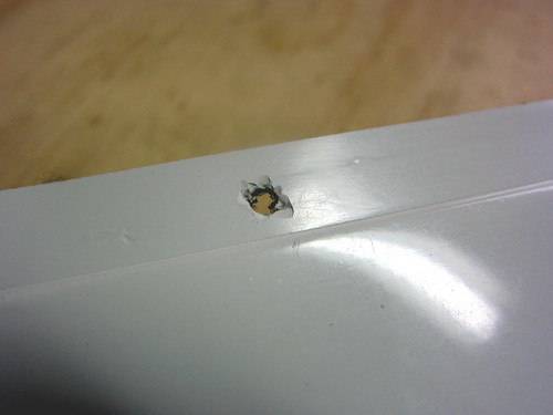
I still need to countersink these holes so hopefully that will hide most of this spalling (and not make it worse). Though, in reality, this flange isn't visible once the fairing is riveted to the elevator, so it doesn't really matter.
17 Aug 2010
After handball today I stopped by to see Jeff's Super Cub, now with wings, then went home to finish up the elevator tip fairings. First up was countersinking the fairing I had already match drilled. I did this with a hand drill set to slow speed and it came out really nice.
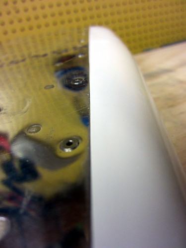
With that done, I finished the dimpling, which required removing the lead counterweight brick for the forward-most holes. With them re-assembled, I cleco'd the fairing back in place, then went to work with the pop-riveter and the CS4-4 rivets. The result looks pretty good to me:
The fit is better than it appears in that picture at the front. It's actually pretty flush all the way around. There are some minor spots where the skin sits slightly proud of the fiberglass, but that will get evened out when I blend the two pieces together using filler and fiberglass cloth.
I did the second elevator in more or less the same manner as the first. The only problem with this piece was that when I was applying the final rivets, two of them failed (the end sphere pulled straight through the body, leaving a rivet of no structural value). The result was that I had to drill them out and re-do the rivets. However, drilling them out left rivet shrapnel inside the fairing. Now, when I move the elevator around, stuff clinks around in there and sounds broken. I'd really like to fix that, but there are no openings into that space now. So I'd have to cut a hole somewhere to accomplish this goal and I'm not sure that's worth it. As an alternative to removing the derelict pieces, I could just drill a small hole and syringe in some thin epoxy, then roll the pieces around until they're stuck in it...
Time for the first of the rudder fairings. The top rudder fairing is nice in that it requires no major modifications and won't be removable. For some reason, the fairing had a 1.25" flange on it as upposed to the 0.5" flange that the other fairing pieces had. So I had to make a big cut in this one to get it to fit in its place.
After trimming all of that off, I did a test fit only to find that the small forward flange on the fairing would run into the lead counterweight brick before the flange was fully inside the rudder skins. So I marked off another small bit to dremel off of the front flange.
With that second trim cut made, the fairing fit inside the counterweight arm of the rudder very nicely.
There were only two problem areas. First, the notch I made at the aft point for the trailing edge extrusion went too high by accident. I'll have to fill that in with microballoons or something. Also, the trailing point of the fairing falls about 1/16" short of the trailing edge of the skin. I may just file the skin corner down to be flush and call it good.
The second problem area was at the front of the counterweight arm, where I had previously bent the skins down around the lead brick. The bend has a bit of an overshoot that I hadn't previously noticed. But against the smooth line of the fairing, it's pretty obvious:
Most of that I was able to beat down with the hand seamer. The rest I'll just fill with microballoons during the blend process.
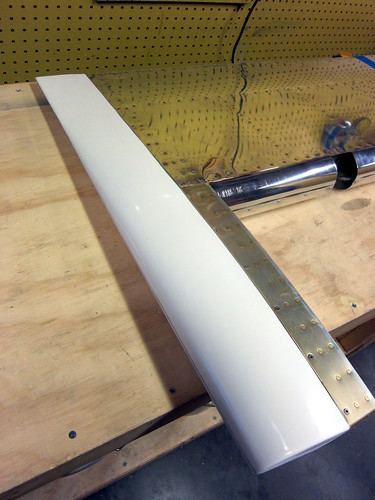
Overall, this fairing has been the best-fitting so far. The joint between the skin and fairing is really flush and smooth almost all the way around.
This fairing is complete until the filling/blending step occurrs (and that could be some time off). Next up will be the lower rudder fairing, which entails wiring up the tail light... but that's for another night.
18 Aug 2010
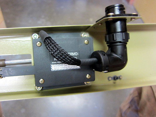
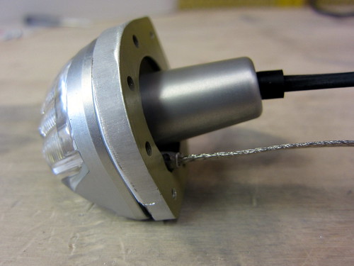
Finally got the strain relief parts in for my circular plastic connectors. I went ahead and put a right-angle one on the elevator trim servo, finishing off this assembly.
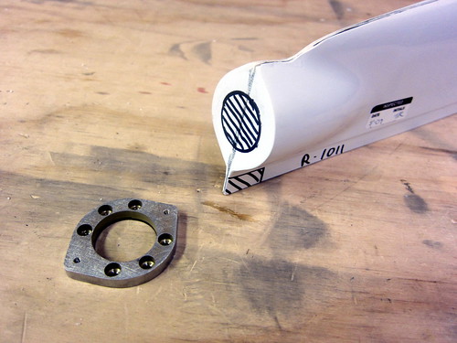
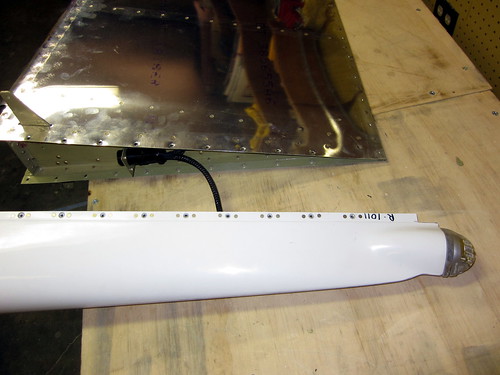
Started work on the bottom rudder fairing. This piece will take a fair amount of time because I'm making it removable, which isn't in the plans, and I'm adding a tail light attachment plate (from Cleaveland Tool). First up was the usual trim cuts to make everything fit. Here they are marked, with the attachment plate laying nearby:
The trailing edge notch I made with the dremel cutoff wheel like usual. The tail light hole I made by drilling successively larger holes until I had a 0.5" hole, then I went in there with a dremel sanding drum to finish it out. Next, I match-drilled the attachment plate to the aft face of the fairing:
The next bit required some creativity. AeroLEDs, the maker of the SunTail LED NAV/Strobe light that I'm using in the rudder, recently released a recommendation that the metal body of the light be grounded in addition to the black ground wire coming out of the back. Apparently this will help quell noise from the strobe light getting into the headsets and interfering with navigation equipment.
So how should I attach a ground to the tail light chassis? The attachment plate would be a good start, but it is just attached to fiberglass, so I need a bonding strap. I initially wanted to attach a small plate to the back of one of the pop rivets that holds the plate to the fairing, but there isn't enough room in there to do this. What I ended up with was milling a notch into the aft face of the plate big enough to get a ring terminal and a star washer around one of the light attach screws. Like this:
This way, when the tail light is screwed on, it presses the star washer down, causing good electrical contact between the plate, the light, and the bonding strap. The result (sans fairing) looks like this:
Next, it was time to rivet the plate to the fairing. There are six countersunk holes in the plate made for CS4-4 pop rivets, but the head of my pop riveter wouldn't fit down into the holes. So I had to fabricate a spacer. I was going to use the bushing that was previously used as a drill guard when drilling the elevator control horns, but it is steel and my bandsaw wouldn't cut it. Instead, I just lopped the ring off of a ring terminal and used the un-crimped shank.
This worked great, except that the last rivet I put in cracked the gel coat adjacent to the plate. Boo. It turns out that the fiberglass had bubbled up behind this spot so there was nothing supporting the non-structural gel coat, so it was doomed to fail. No biggy, I'll just blend over this when I blend the plate to the fairing later.
Other than the crack, I'm really happy with how the tail light install came out. It looks great test-assembled!
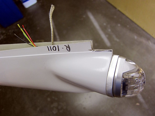
I went ahead and put the (provided) molex connector on the tail light wires, and wired an extra ground wire into the usually empty fifth pin. I need to get a pair of faston connectors to connect the other end of the bonding strap to the spare ground wire, then the tail light will be complete.
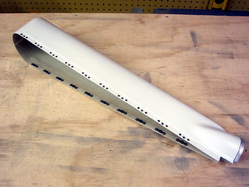
Continuing on with the lower rudder fairing, I match-drilled all of the holes from the rudder skin into the fairing, but rather than stopping at #30 for CS4-4 pop rivets, I am going to #27 for #6 screws. I want my lower rudder fairing to be removable so I can gain access to the electrical connectors in there. This means that I'll need nutplates behind each hole, so I used a nutplate as a template and drilled rivet holes next to each screw hole. Countersinking these was straightforward. I also went ahead and dimpled the holes in the rudder skin for #6 screw heads.
All that is left for this piece is to put nutplates on it. I'm leaving that for another day as it's time for bed.
20 Aug 2010
Got the nutplates put onto the bottom rudder fairing, rendering it complete aside from some minor blending to do around the tail light mount plate and its associated crack.
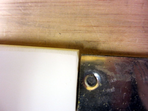
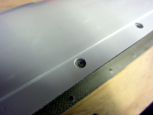
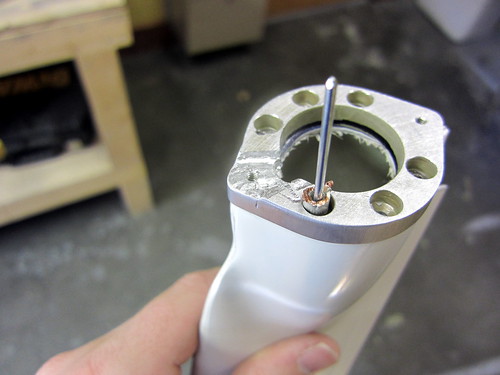
I had planned on using AN507-C632R8 stainless screws to attach the fairing to the rudder, but they are too long for the aft-most holes:
I'll probably replace these two with -6R6, or possibly just replace them all with the shorter bolts so that I have homogeniety of parts.
With the fairing done, I went ahead and finished off the tail light wiring. I spent some time on this and made it look really good. Partially because I want my electrical system to be really solid, but also because it gave me a chance to mess with my new heat gun and heat shrink label printer.
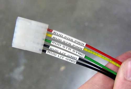
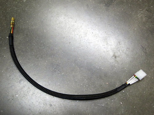
I spliced the two ground wires from the tail light into a single wire going into the rudder CPC. There shouldn't be any current off the chassis ground; it's just a shield wire, essentially. So there was no need to upsize the wire gauge. I put heat shrink over the splice, then wrapped the entire wire harness in abrasion-resistant weave, and heat shrunk the ends. The result looks like this:
Next, I knocked the pins from rudder trim out of the CPC so that I could thread them through a strain relief clamp. Both wire harnesses were put through the clamp and everything was tightened down. The result looks professional and doesn't interfere with the nearby AN507 screw.
I left enough slack between the CPC and the tail light Molex connector that I can remove the fairing without disconnecting the tail light (as seen above) or I can pull the tail light off and get to the Molex connector without taking the fairing off.
With that, the rudder is finished other than blending, trim, and paint.
22 Aug 2010
Today was the big empennage attach day! I started in the morning with Nina's help, getting the tail cone moved out into the driveway and the horizontal stabilizer placed on top of it.
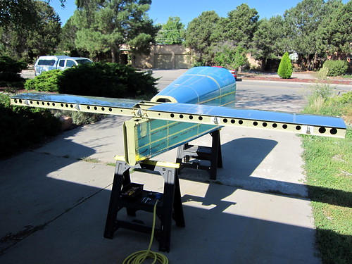
It took quite a few iterations to get the distances from the HS tips to the centerline of the tailcone to be even on both sides, but we finally managed to get it square and the bolt holes were match drilled, deburred, and bolted down. Sitting on my saw horses, the tailcone + horizontal stabilizer combo was balanced well, but it didn't take much for it to want to roll. I'm glad it wasn't windy. At some point during this part of the show, Bob showed up to lend a hand. Having a second person for this section of the plans is pretty much mandatory, and I would recommend three for many portions.
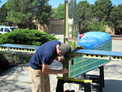
Next up was the vertical stabilizer, which also went on without a hitch. Some of the lower bolts were a pain to get tightened down since one arm had to be jammed all the way into the small access panels at the rear of the tail cone.
The elevators came next, and would have been a pain with just two people. Luckily, Jeff and Skip arrived from the local EAA chapter to see what was going on and lent a hand for the remainder of the day's activities.
Jeremy, Bob, and I had already worked out the appropriate rod-end bearing distance for the elevators to not come in contact with the horizontal stabilizer, but when we mounted them again today, there was definitely some contact. We tried adjusting the rod-end bearing displacements, but this made the center hinge hole not line up correctly. I definitely didn't want binding in this joint, so I reset the rod-end bearings to their original positions and just shaved down the inboard edge of the elevator counterweight tips until the correct spacing was achieved. In the end it wasn't a big deal; very little material needed to be removed. A mill file and the mini-scotchbright wheel attachment for my die grinder did the trick. A set of temporary assembly pins from Avery Tools also proved invaluable here.
I tested the desired deflection angles for the elevators, got exactly the right angle for the nose-down setting, but was two degrees short on the nose-up setting. So I used the scotch bright grinder again and took a very small amount of material off of the nose-up elevator stop bar. Now the angles are perfect.
With both elevators in place, the pushrod came out of storage and was attached at both ends. With the aft rod-end bearing in place and threaded half-way into the threaded insert, the forward rod-end bearing had to be fully threaded into the insert in order to make the desired angle on the bellcrank. This is fine, I'll probably average it out by backing out some fixed number of turns from the forward bearing and going inwards by the same number on the aft one.

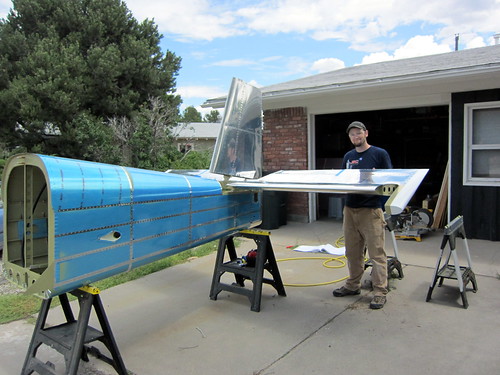
Then, it was time for the final piece. I was worried about the rudder attachment because, with its three hinges, it could be a real bear to get it aligned. Much to my surprise, however, it went in perfectly the first time with Van's recommended distances for the three rod-end bearings. The gap between the counterweight and the vertical stabilizer was also perfect and straight. Cool!
I decided to skip the elevator trim mechanism install for now; I didn't relish the idea of threading through those cables, just to un-do it later. I'll save that for final assembly. Other than the tip fairings for the horizontal and vertical stabilizers, the empennage kit plans are complete! Non-plans tasks remaining include rudder trim and blending the fairings, but that's it!
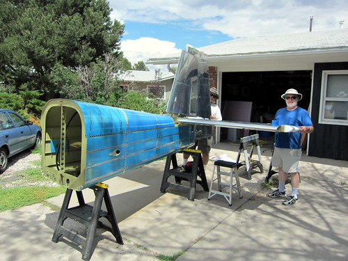
When we had the assembly complete, we could see that a rain storm was moving in so we made a mad dash to get everything disassmbled and stored in the house. We didn't quite finish in time. I'm sorry there aren't more pictures of the fully-assembled tail.
Had to spend some time mopping up all the water from the horizontal stabilizer and tail cone, but no harm was done.
23 Aug 2010
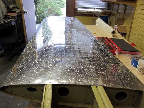
With the empennage attach activities out of the way and the elevator fairings in place, I am now ready to do the initial fitting of the horizontal stabilizer fairings.
First step was to cut back about an inch from the aft ends of the flange. This allows the fairing to fit in front of the forward spar of the horizontal stabilizer. With those cuts made, I held the fairing in place while match-drilling the skin holes into the fiberglass, starting from the front and working back—clecoing as I went. The piece initially wouldn't seat all the way down despite having the called-for 0.5" of flange. After filing the flange down ever-so-slightly, it fits nicely, though there are some irregularities in the curvature of the nose of the stabilizer skin that don't sit perfectly flat on the fiberglass flange. This'll be fixed during the blending phase.
With the tip fairing in place, I lowered the elevator counterbalance arm into place and drew a line showing where I needed to cut the fairing in order for the counterweight to be clear for its entire travel. This line is shown, above. I made this cut with the dremel cut-off wheel, reattached, found some spots that weren't cut far enough, and repeated. Three times. Now, I have a great-looking space between the tip fairing and the elevator arm:
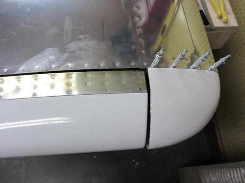
The only problem here is that the tip fairing sticks out about 1/8" farther than the elevator fairing. Not a lot I can do about that that would be worth the effort. I've only done one side; the other will proceed just like this one. It only takes about an hour to get this far with one. Now the real fun can begin: building up the aft face of the tip fairing with a raw fiberglass layup. I don't have the supplies or tools for that, yet, so that's probably a way off still.
It's been awhile; I've been out of town for work, but I'm back now and spent a quick hour today getting some tasks ready for the main event of the empennage attach chapter. Namely, the day I'll fully attach the entire tail section of the aircraft in my driveway.
While I was gone, I looked through the plans and made a list of small tasks that needed to be taken care of before I could do the actual attachment, and set about doing some of those things today. First off, the elevator trim bracket was a bit long on the aft edge for the holes in the aft deck to line up with the nutplates in the bracket now that I've bolted and riveted the aft end of the tailcone together. It was only long by about 1/16", so I just took the scotchbrite wheel to that edge and now it fits like a champ.
Next, I checked my hardware bins and made sure I had the necessary bolts and washers for the actual attachment. No problems there.
Finally, I addressed the problem I had earlier with the elevator trim bellcrank mechanism binding rather than rotating freely. I measured the gap as-built and the thickness of the bellcrank plate plus the two washers was too large by 0.02". Not much, but enough to make it too tight. The suggested fix from the forums was to grind down the washers using a belt sander (which I don't have). Instead, I just took the scotchbrite wheel to the sides of the bellcrank plate and took off the primer and a bit of the metal. It did this slowly and in many iterations to ensure that I wasn't taking off too much. Each time, I'd load the parts back up and rotate it a few times and the washers would leave marks where the plate was still too thick. Once I got the right amount off, it spins freely. The change in thickness is not visually perceptible, so I'm not concerned about compromosing the structural integrity of the plate. Here's a picture of the bellcrank mechanism from the bottom after everything was fully assembled.
Of course, this also means that I finally installed the T3-12A servo in its spot just aft of the bellcrank. I haven't connected the wires to the CPC on the drop plate yet because I want to put a strain relief cap on it but I don't have one in stock. Time for a mouser.com order.
And here's the final view of the forward end of the trim push-pull cables installed onto the bellcrank.
It was really hard getting the right-side cable through the mounting bracket; for some reason that hole seems to be just a fraction smaller than the other. But I did manage to get it through and they look great. I'm thinking I should take off those labels that read "Not for use in aircraft" in bright red letters... (a note to those who are concerned by this, it's a liability thing... the cables are perfectly acceptable for use in aircraft and are actually supplied by the kit manufacturer).
The bellcrank is shown in the full nose-down trim position here, with the cables fully extended on this end.
16 Aug 2010
I did a couple more mini-tasks getting ready for the big empennage attach day in the ill-defined future, namely making the elevator bellcrank angle template out of some foam board and getting the forward end of the elevator trim push-pull cables tightened down at the right length. The only remaining tasks here are to make the 2x4 block for squaring the horizontal stabilier and to put the rod-end bearings into the rudder. One those are done, I'll be on hold with empennage attach until I have a full day with a helper that I can spend doing the rest of the chapter. It's possible this will occur this coming Sunday, or perhaps it's weeks away. So I moved on to starting the empennage fairings chapter in the meantime.
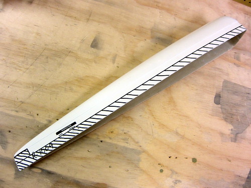
The first fairings to work on in the empennage fairings chapter are the elevator tips. These, along with the upper rudder fairing, are the easiest because they don't require significant modification and they don't need to be removable. The flange on the first elevator fairing I grabbed was already at (or slightly smaller than) the recommended half-inch in width, so no trimming was necessary there. I took a razor to the flange inset corner and cleaned out some small chaff. Then I took a dremel cutoff wheel to the aft end of the flange to remove a small chunk in order to make room for the elevator trailing edge extrusion piece. Cutting the fiberglass with the cutoff wheel was surprisingly easy.
With that cut made, the fairing slipped very nicely into my left elevator. There was no interference from the static wick attachment platenuts. There was, however, a huge gap between the fairing and the skin except right at the forward and aft ends.
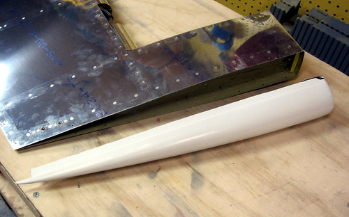
I guessed that when drilled and cleco'd together, this gap would vanish. I was right. It's fortunate that there was no gap at the forward end, where the drilling begins. As I drilled and cleco'd one hole, it would cinch up the gap for the next drilling, and so-on. Here's the result after all the match drilling.
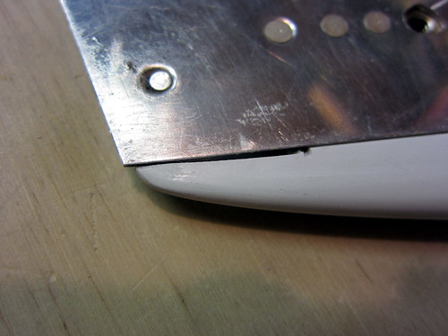
One problem that did not go away with drilling and clecoing the fairing to the skin, however, was that the fairing was about 1/16" too long.
I put a sanding drum in the dremel and trimmed down the offending corner until they were reasonably flush. I'll eventually be coating this entire joint up with filler and sanding it all smooth so it should look like one continuous piece.
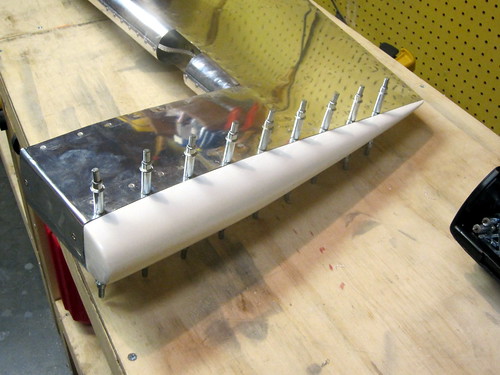
The last thing I did tonight was take the fairing back off the left elevator and start dimpling the holes. For the aft-most holes, I had to use the pop-rivet dimple die set, so I just used it for all holes. I wasn't able to get the forward-most hole on each side without removing the lead counterweight, which I put off for another day. So 20 of the 22 holes are now dimpled.
The fairing showed considerable spall from the drilling, though only in the outer finish coating. The hole in the underlying fiberglass looked very good.
I still need to countersink these holes so hopefully that will hide most of this spalling (and not make it worse). Though, in reality, this flange isn't visible once the fairing is riveted to the elevator, so it doesn't really matter.
17 Aug 2010
After handball today I stopped by to see Jeff's Super Cub, now with wings, then went home to finish up the elevator tip fairings. First up was countersinking the fairing I had already match drilled. I did this with a hand drill set to slow speed and it came out really nice.
With that done, I finished the dimpling, which required removing the lead counterweight brick for the forward-most holes. With them re-assembled, I cleco'd the fairing back in place, then went to work with the pop-riveter and the CS4-4 rivets. The result looks pretty good to me:
The fit is better than it appears in that picture at the front. It's actually pretty flush all the way around. There are some minor spots where the skin sits slightly proud of the fiberglass, but that will get evened out when I blend the two pieces together using filler and fiberglass cloth.
I did the second elevator in more or less the same manner as the first. The only problem with this piece was that when I was applying the final rivets, two of them failed (the end sphere pulled straight through the body, leaving a rivet of no structural value). The result was that I had to drill them out and re-do the rivets. However, drilling them out left rivet shrapnel inside the fairing. Now, when I move the elevator around, stuff clinks around in there and sounds broken. I'd really like to fix that, but there are no openings into that space now. So I'd have to cut a hole somewhere to accomplish this goal and I'm not sure that's worth it. As an alternative to removing the derelict pieces, I could just drill a small hole and syringe in some thin epoxy, then roll the pieces around until they're stuck in it...
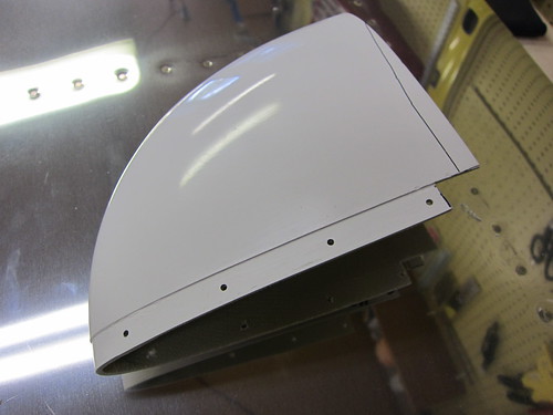
Time for the first of the rudder fairings. The top rudder fairing is nice in that it requires no major modifications and won't be removable. For some reason, the fairing had a 1.25" flange on it as upposed to the 0.5" flange that the other fairing pieces had. So I had to make a big cut in this one to get it to fit in its place.
After trimming all of that off, I did a test fit only to find that the small forward flange on the fairing would run into the lead counterweight brick before the flange was fully inside the rudder skins. So I marked off another small bit to dremel off of the front flange.
With that second trim cut made, the fairing fit inside the counterweight arm of the rudder very nicely.
There were only two problem areas. First, the notch I made at the aft point for the trailing edge extrusion went too high by accident. I'll have to fill that in with microballoons or something. Also, the trailing point of the fairing falls about 1/16" short of the trailing edge of the skin. I may just file the skin corner down to be flush and call it good.
The second problem area was at the front of the counterweight arm, where I had previously bent the skins down around the lead brick. The bend has a bit of an overshoot that I hadn't previously noticed. But against the smooth line of the fairing, it's pretty obvious:
Most of that I was able to beat down with the hand seamer. The rest I'll just fill with microballoons during the blend process.
Overall, this fairing has been the best-fitting so far. The joint between the skin and fairing is really flush and smooth almost all the way around.
This fairing is complete until the filling/blending step occurrs (and that could be some time off). Next up will be the lower rudder fairing, which entails wiring up the tail light... but that's for another night.
18 Aug 2010
Finally got the strain relief parts in for my circular plastic connectors. I went ahead and put a right-angle one on the elevator trim servo, finishing off this assembly.
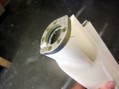
Started work on the bottom rudder fairing. This piece will take a fair amount of time because I'm making it removable, which isn't in the plans, and I'm adding a tail light attachment plate (from Cleaveland Tool). First up was the usual trim cuts to make everything fit. Here they are marked, with the attachment plate laying nearby:
The trailing edge notch I made with the dremel cutoff wheel like usual. The tail light hole I made by drilling successively larger holes until I had a 0.5" hole, then I went in there with a dremel sanding drum to finish it out. Next, I match-drilled the attachment plate to the aft face of the fairing:
The next bit required some creativity. AeroLEDs, the maker of the SunTail LED NAV/Strobe light that I'm using in the rudder, recently released a recommendation that the metal body of the light be grounded in addition to the black ground wire coming out of the back. Apparently this will help quell noise from the strobe light getting into the headsets and interfering with navigation equipment.
So how should I attach a ground to the tail light chassis? The attachment plate would be a good start, but it is just attached to fiberglass, so I need a bonding strap. I initially wanted to attach a small plate to the back of one of the pop rivets that holds the plate to the fairing, but there isn't enough room in there to do this. What I ended up with was milling a notch into the aft face of the plate big enough to get a ring terminal and a star washer around one of the light attach screws. Like this:
This way, when the tail light is screwed on, it presses the star washer down, causing good electrical contact between the plate, the light, and the bonding strap. The result (sans fairing) looks like this:
Next, it was time to rivet the plate to the fairing. There are six countersunk holes in the plate made for CS4-4 pop rivets, but the head of my pop riveter wouldn't fit down into the holes. So I had to fabricate a spacer. I was going to use the bushing that was previously used as a drill guard when drilling the elevator control horns, but it is steel and my bandsaw wouldn't cut it. Instead, I just lopped the ring off of a ring terminal and used the un-crimped shank.
This worked great, except that the last rivet I put in cracked the gel coat adjacent to the plate. Boo. It turns out that the fiberglass had bubbled up behind this spot so there was nothing supporting the non-structural gel coat, so it was doomed to fail. No biggy, I'll just blend over this when I blend the plate to the fairing later.
Other than the crack, I'm really happy with how the tail light install came out. It looks great test-assembled!
I went ahead and put the (provided) molex connector on the tail light wires, and wired an extra ground wire into the usually empty fifth pin. I need to get a pair of faston connectors to connect the other end of the bonding strap to the spare ground wire, then the tail light will be complete.
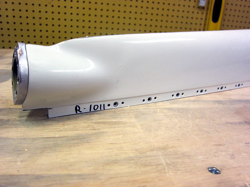
Continuing on with the lower rudder fairing, I match-drilled all of the holes from the rudder skin into the fairing, but rather than stopping at #30 for CS4-4 pop rivets, I am going to #27 for #6 screws. I want my lower rudder fairing to be removable so I can gain access to the electrical connectors in there. This means that I'll need nutplates behind each hole, so I used a nutplate as a template and drilled rivet holes next to each screw hole. Countersinking these was straightforward. I also went ahead and dimpled the holes in the rudder skin for #6 screw heads.
All that is left for this piece is to put nutplates on it. I'm leaving that for another day as it's time for bed.
20 Aug 2010
Got the nutplates put onto the bottom rudder fairing, rendering it complete aside from some minor blending to do around the tail light mount plate and its associated crack.
I had planned on using AN507-C632R8 stainless screws to attach the fairing to the rudder, but they are too long for the aft-most holes:
I'll probably replace these two with -6R6, or possibly just replace them all with the shorter bolts so that I have homogeniety of parts.
With the fairing done, I went ahead and finished off the tail light wiring. I spent some time on this and made it look really good. Partially because I want my electrical system to be really solid, but also because it gave me a chance to mess with my new heat gun and heat shrink label printer.
I spliced the two ground wires from the tail light into a single wire going into the rudder CPC. There shouldn't be any current off the chassis ground; it's just a shield wire, essentially. So there was no need to upsize the wire gauge. I put heat shrink over the splice, then wrapped the entire wire harness in abrasion-resistant weave, and heat shrunk the ends. The result looks like this:
Next, I knocked the pins from rudder trim out of the CPC so that I could thread them through a strain relief clamp. Both wire harnesses were put through the clamp and everything was tightened down. The result looks professional and doesn't interfere with the nearby AN507 screw.
I left enough slack between the CPC and the tail light Molex connector that I can remove the fairing without disconnecting the tail light (as seen above) or I can pull the tail light off and get to the Molex connector without taking the fairing off.
With that, the rudder is finished other than blending, trim, and paint.
22 Aug 2010
Today was the big empennage attach day! I started in the morning with Nina's help, getting the tail cone moved out into the driveway and the horizontal stabilizer placed on top of it.
It took quite a few iterations to get the distances from the HS tips to the centerline of the tailcone to be even on both sides, but we finally managed to get it square and the bolt holes were match drilled, deburred, and bolted down. Sitting on my saw horses, the tailcone + horizontal stabilizer combo was balanced well, but it didn't take much for it to want to roll. I'm glad it wasn't windy. At some point during this part of the show, Bob showed up to lend a hand. Having a second person for this section of the plans is pretty much mandatory, and I would recommend three for many portions.
Next up was the vertical stabilizer, which also went on without a hitch. Some of the lower bolts were a pain to get tightened down since one arm had to be jammed all the way into the small access panels at the rear of the tail cone.
The elevators came next, and would have been a pain with just two people. Luckily, Jeff and Skip arrived from the local EAA chapter to see what was going on and lent a hand for the remainder of the day's activities.
Jeremy, Bob, and I had already worked out the appropriate rod-end bearing distance for the elevators to not come in contact with the horizontal stabilizer, but when we mounted them again today, there was definitely some contact. We tried adjusting the rod-end bearing displacements, but this made the center hinge hole not line up correctly. I definitely didn't want binding in this joint, so I reset the rod-end bearings to their original positions and just shaved down the inboard edge of the elevator counterweight tips until the correct spacing was achieved. In the end it wasn't a big deal; very little material needed to be removed. A mill file and the mini-scotchbright wheel attachment for my die grinder did the trick. A set of temporary assembly pins from Avery Tools also proved invaluable here.
I tested the desired deflection angles for the elevators, got exactly the right angle for the nose-down setting, but was two degrees short on the nose-up setting. So I used the scotch bright grinder again and took a very small amount of material off of the nose-up elevator stop bar. Now the angles are perfect.
With both elevators in place, the pushrod came out of storage and was attached at both ends. With the aft rod-end bearing in place and threaded half-way into the threaded insert, the forward rod-end bearing had to be fully threaded into the insert in order to make the desired angle on the bellcrank. This is fine, I'll probably average it out by backing out some fixed number of turns from the forward bearing and going inwards by the same number on the aft one.
Then, it was time for the final piece. I was worried about the rudder attachment because, with its three hinges, it could be a real bear to get it aligned. Much to my surprise, however, it went in perfectly the first time with Van's recommended distances for the three rod-end bearings. The gap between the counterweight and the vertical stabilizer was also perfect and straight. Cool!
I decided to skip the elevator trim mechanism install for now; I didn't relish the idea of threading through those cables, just to un-do it later. I'll save that for final assembly. Other than the tip fairings for the horizontal and vertical stabilizers, the empennage kit plans are complete! Non-plans tasks remaining include rudder trim and blending the fairings, but that's it!
When we had the assembly complete, we could see that a rain storm was moving in so we made a mad dash to get everything disassmbled and stored in the house. We didn't quite finish in time. I'm sorry there aren't more pictures of the fully-assembled tail.
Had to spend some time mopping up all the water from the horizontal stabilizer and tail cone, but no harm was done.
23 Aug 2010
With the empennage attach activities out of the way and the elevator fairings in place, I am now ready to do the initial fitting of the horizontal stabilizer fairings.
First step was to cut back about an inch from the aft ends of the flange. This allows the fairing to fit in front of the forward spar of the horizontal stabilizer. With those cuts made, I held the fairing in place while match-drilling the skin holes into the fiberglass, starting from the front and working back—clecoing as I went. The piece initially wouldn't seat all the way down despite having the called-for 0.5" of flange. After filing the flange down ever-so-slightly, it fits nicely, though there are some irregularities in the curvature of the nose of the stabilizer skin that don't sit perfectly flat on the fiberglass flange. This'll be fixed during the blending phase.
With the tip fairing in place, I lowered the elevator counterbalance arm into place and drew a line showing where I needed to cut the fairing in order for the counterweight to be clear for its entire travel. This line is shown, above. I made this cut with the dremel cut-off wheel, reattached, found some spots that weren't cut far enough, and repeated. Three times. Now, I have a great-looking space between the tip fairing and the elevator arm:
The only problem here is that the tip fairing sticks out about 1/8" farther than the elevator fairing. Not a lot I can do about that that would be worth the effort. I've only done one side; the other will proceed just like this one. It only takes about an hour to get this far with one. Now the real fun can begin: building up the aft face of the tip fairing with a raw fiberglass layup. I don't have the supplies or tools for that, yet, so that's probably a way off still.
| <-- July 2010 | September 2010 --> |