| Workshop | Empennage | Wings | Fuselage | Contact |
| <-- June 2010 | August 2010 --> |
Chronological Updates, July, 2010
6 Jul 2010
The riveting of the tail cone continues. I got as far as I could with back riveting and have now transitioned into bucking the rivets that can't be reached with the back rivet set.
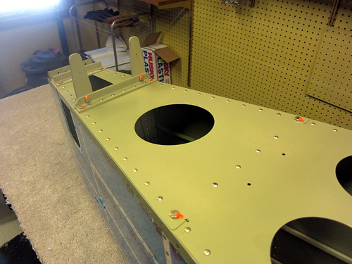
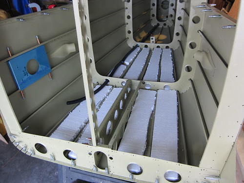
Not much to see in the way of pictures... there's just less and less clecos everyday. I did take a break from skin rivets for awhile and put the elevator bellcrank ribs together
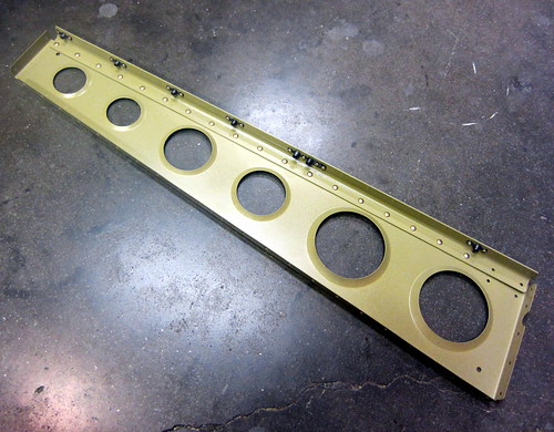
In this shot you can see the extra nutplate I added to the right-side rib for the aft-right corner of the battery box.
Not much left on the lower-half of the tail cone in the way of rivets... I figure one more good evening of it and it'll be done. Got all of the bulkhead and frame rivets complete as well as all of the stiffeners. Also did one of the two side/bottom skin joints.
15 Jul 2010
Jeremy and I did one more evening of riveting to knock out the remaining skin rivets. This included attaching the elevator bellcrank ribs. However, before attaching these two parts, I added a last-minute customization. I was thinking that it might be good to have an easy way to route cables, tubes, etc. from one side of the tail cone to the other in a tidy manner. My solution was to pass them through the aft-most lightening holes in the bellcrank ribs. This area is essentially unused space and does not interfere with the bellcrank mecahanism.
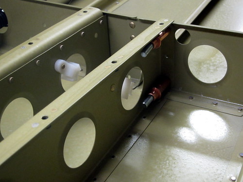
I added a lightening hole wire tie anchor to each of the holes in such a position that it wouldn't get in the way when doing the rivets that attach the aft flange of the rib to the F-1007 frame. Now, if I have something that needs to be routed from one side to the other, I can just pass it through here and fasten it to the anchors. Piece of cake.
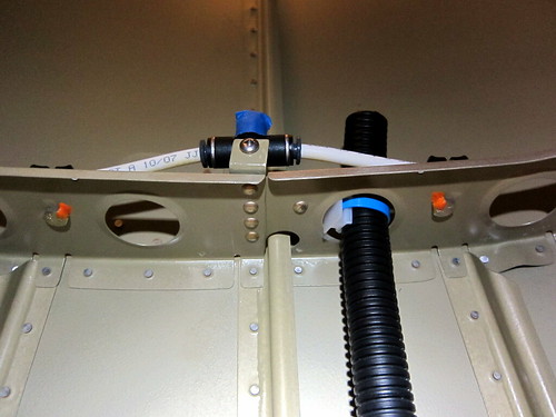
With all of the principal riveting done before moving on to the aft deck, I decided to finish up a bit of accessory work. I started with the static air system. Because I'm going to route my static air lines up the aft face of the F-1008 frame, I can go ahead and put in the hardware to secure it since the aft face doesn't get in the way of the frame/skin rivets.
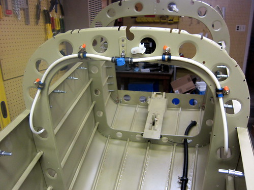
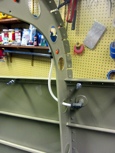
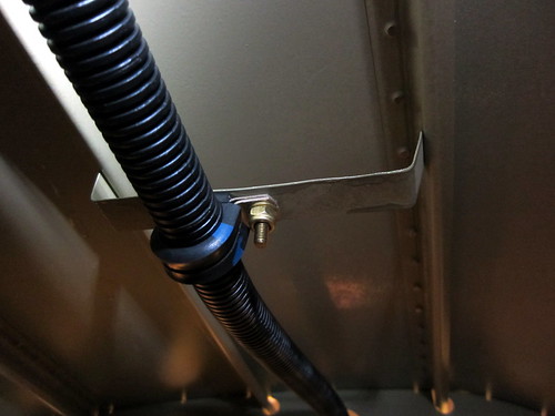
The static air ports have 90° fittings on them which face aft. The white air tubing leaves these fittings and passes immediately through a lightening hole in the F-1008 such that no hardware is required to keep the tubing from touching the hole edges. From there, the tube curves around and passes along the aft face of the frame until it meets the T-connector that I installed earlier. A pair of adel clamps (-04 size) keeps the tubing in place on each side. I hit the bolts with inspection lacquer just to be safe. Here's another view of the air line leaving the right angle fitting and heading through the lightening hole:
Next, I installed most of the bottom conduit that runs from just aft of the F-1006 bulkhead to just aft of the F-1010 bulkhead. This included three Click Bond threaded stand-offs with adel clamps (-12 size) and three lightening hole wire tie anchors with wire ties and RTV.
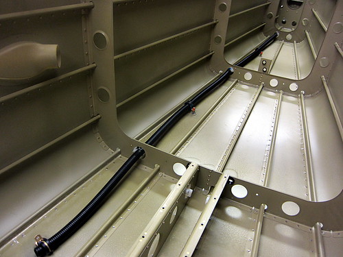
Here's a closeup of the hardware I used on the Click Bond studs:

I made an elevated "platform" out of two nuts with a lock washer inbetween. Then the adel clamp, a plain washer, and an elastic stop nut on top. This keeps the conduit from ever touching the skin of the plane. The conduit will hopefully be large enough to hold the NAV1 antenna cable, tail light wires, rudder trim wires, elevator trim wires, and vertical stabilizer tip fairing accessory wires.
With this done, it was time to get started on the aft deck. I've been crazy busy at work lately so work has come in small chunks here and there, but I did manage to get a friend from work to come down and help me replace the bad rivets I had identified in the skins and then do all of the rivets connecting the aft deck to the longerons, up elevator stop, and F-1009 frame.
Just a couple more to do and it's time to start adding the bolts in this region. This means that it is almost time to button up the top of the tail cone, which will entail moving my primary work space into the garage!
17 July 2010
Jeremy and I made quick work of the remaining rivets in the aft deck, and I added the eight bolts in that area. They were torqued to 25 inch-pounds and marked with inspection lacquer.
With the aft deck work complete, the next step is to add the top stiffeners and skin. However, this makes the tail cone too large to fit out the door. So with that, it was time to re-locate to the garage!
I quickly back-riveted the ELT antenna doubler on to the underside of the aft top skin, placed the A and B stiffeners onto the tail cone, then cleco'd the skin to the stiffeners and frames. I took a cue from Mark and Angela Lanier's project and only cleco'd on the horizontal top bits and let the skin stick striaght off to the sides. This allows my rivet bucker to access the underside of the top rivets without having to crawl inside.
Jeremy and I made quick work of these rivets last night and this morning. From there, we bent one side down and cleco'd it in place, but left the other hanging. That way, we were able to do the entire left side without having to crawl inside. Having completed that and then bent and cleco'd the other side in place, the result looks like this:
By reaching in through the F-1009 hole (the D-shaped hole, above), we should be able to buck all of the rivets that attach the skin to the F-1009 frame, as well as the aft-most holes in the longeron. By reaching around past the front end of the skin, we should be able to do a bunch of the forward-most rivets in the longeron as well. This leaves only the curved portion on the right side of the F-1008 frame and a bit of the longeron that will need to be done from inside. First, I need to get some styrofoam cut up to make a platform so that Jeremy doesn't bend up the fragile bits inside the tail cone.
Today, somewhere along the left longeron of the tail cone, we put the 5000th rivet into the plane!
22 Jul 2010
I was originally thinking that we would buck the reachable rivets on the tail cone prior to having Jeremy crawling inside to get the unreachable ones. But after discussing it, we decided that he could do a better job from inside and there weren't all that many anyway. So I built up a platform of foam and blankets so that he wouldn't bend anything in there. I used some of the styrofoam that the came as packing material inside the empennage shipping crate for the base layer.
It was about an inch thick and this was high enough to get above the stiffeners. Above these pieces, I cut out some 2" pink foam blocks using a sawzall and this got the platform up above the level of the frame bottoms. On top of that I just layed a blanket down and that seemed to be enough. I'll save the foam pieces for any future need to get inside the tail cone.
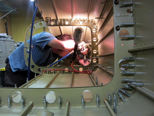
Anyway, here's the requisite RV-10 construction photo of some poor sap squished inside the aft end of the tail cone:
We made quick work of the remaining 50 rivets and I think he was thankful to be out of there.
At that point, the rivets on the tail cone were essentially done (for now). The forward skin doesn't go on until the tail cone gets attached to the fuselage, and that's years away. So I turned my attention from rivets to the remaining internal accessories.
First up was the upper conduit. This conduit's aft terminus is at the F-1008 frame next to the static air T junction. I used the lightening hole wire tie anchor that I had riveted in earlier to wire tie the conduit in place. I hit it with a dab of black RTV to keep it all rigid.
The treatment at the F-1007 frame was essentially the same. Half way between the two frames I pop-riveted in the custom drop bracket I had fabricated earlier. From there, I attached an adel clamp to support the conduit. I used brass hardware because this adel clamp is right above where the magnetometers will eventually sit.
Forward of the F-1007 frame, the conduit remains incomplete since its drop bracket will get in the way of riveting on the forward ends of the A and B stiffeners under the forward top skin.
The second task to take care of was the rails for the magnetometer shelf. These were just a pair of angle aluminum bars that I had fabricated and primer earlier. I attached them to the bottom side of the longeron roughly half-way between the F-1007 and F-1008 frames and about 10 cm apart from each other. The attachment hardware was again all brass to keep any ferrous metal as far away from the magnetometers as possible.
The magnetometer platform that sits atop these rails will be fabricated later, when I know more about what the mounting requirements of the magnetometers are. So for now, this bit is done. In fact, this is the end of the tail cone chapter of the plans! Time to move on to the empennage attach chapter.
23 Jul 2010
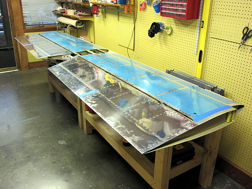
With the tail cone mostly done, it was time to get started on attaching all of the subassemblies I had built to date together. The first step was to secure the horizontal stabilizer to the work benches with some woodscrews. From there, each of the elevators was attached to the horizontal stabilizers one at a time.
This was a tedious process because getting those two AN3 bolts through the rod-end bearings is a bit tricky and requires two people (at least in my setup). Once the two bolts are in place, you measure the clearance between the counterweight arm and the side of the horizontal stabilizer... then take the whole thing off again to make an adjustment to the rod-end bearing. Rinse, repeat. Then do the other elevator. Bit of a pain, but it when it was done, the results looked great!
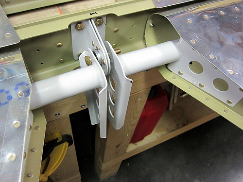
Drilling the hole in the control horns for the central bearing was straightforward, and the AN4 bolt that connects both sides went through without a hitch. However, I have no idea how I'm going to thread washers into the gaps between the bearing and the horns. I suspect I need a new tool or something for that. I'm going to have to ask some of my builder friends what to do here.
Unfortunately I'm leaving town in a day or so for three weeks. So there will be another work-related RV-10 hiatus. :(
The riveting of the tail cone continues. I got as far as I could with back riveting and have now transitioned into bucking the rivets that can't be reached with the back rivet set.
Not much to see in the way of pictures... there's just less and less clecos everyday. I did take a break from skin rivets for awhile and put the elevator bellcrank ribs together
In this shot you can see the extra nutplate I added to the right-side rib for the aft-right corner of the battery box.
Not much left on the lower-half of the tail cone in the way of rivets... I figure one more good evening of it and it'll be done. Got all of the bulkhead and frame rivets complete as well as all of the stiffeners. Also did one of the two side/bottom skin joints.
15 Jul 2010
Jeremy and I did one more evening of riveting to knock out the remaining skin rivets. This included attaching the elevator bellcrank ribs. However, before attaching these two parts, I added a last-minute customization. I was thinking that it might be good to have an easy way to route cables, tubes, etc. from one side of the tail cone to the other in a tidy manner. My solution was to pass them through the aft-most lightening holes in the bellcrank ribs. This area is essentially unused space and does not interfere with the bellcrank mecahanism.
I added a lightening hole wire tie anchor to each of the holes in such a position that it wouldn't get in the way when doing the rivets that attach the aft flange of the rib to the F-1007 frame. Now, if I have something that needs to be routed from one side to the other, I can just pass it through here and fasten it to the anchors. Piece of cake.
With all of the principal riveting done before moving on to the aft deck, I decided to finish up a bit of accessory work. I started with the static air system. Because I'm going to route my static air lines up the aft face of the F-1008 frame, I can go ahead and put in the hardware to secure it since the aft face doesn't get in the way of the frame/skin rivets.
The static air ports have 90° fittings on them which face aft. The white air tubing leaves these fittings and passes immediately through a lightening hole in the F-1008 such that no hardware is required to keep the tubing from touching the hole edges. From there, the tube curves around and passes along the aft face of the frame until it meets the T-connector that I installed earlier. A pair of adel clamps (-04 size) keeps the tubing in place on each side. I hit the bolts with inspection lacquer just to be safe. Here's another view of the air line leaving the right angle fitting and heading through the lightening hole:
Next, I installed most of the bottom conduit that runs from just aft of the F-1006 bulkhead to just aft of the F-1010 bulkhead. This included three Click Bond threaded stand-offs with adel clamps (-12 size) and three lightening hole wire tie anchors with wire ties and RTV.
Here's a closeup of the hardware I used on the Click Bond studs:
I made an elevated "platform" out of two nuts with a lock washer inbetween. Then the adel clamp, a plain washer, and an elastic stop nut on top. This keeps the conduit from ever touching the skin of the plane. The conduit will hopefully be large enough to hold the NAV1 antenna cable, tail light wires, rudder trim wires, elevator trim wires, and vertical stabilizer tip fairing accessory wires.
With this done, it was time to get started on the aft deck. I've been crazy busy at work lately so work has come in small chunks here and there, but I did manage to get a friend from work to come down and help me replace the bad rivets I had identified in the skins and then do all of the rivets connecting the aft deck to the longerons, up elevator stop, and F-1009 frame.
Just a couple more to do and it's time to start adding the bolts in this region. This means that it is almost time to button up the top of the tail cone, which will entail moving my primary work space into the garage!
17 July 2010
Jeremy and I made quick work of the remaining rivets in the aft deck, and I added the eight bolts in that area. They were torqued to 25 inch-pounds and marked with inspection lacquer.
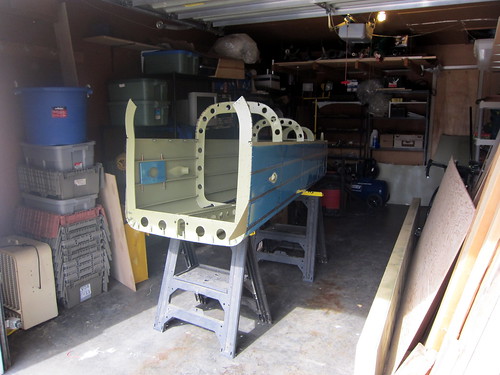
With the aft deck work complete, the next step is to add the top stiffeners and skin. However, this makes the tail cone too large to fit out the door. So with that, it was time to re-locate to the garage!
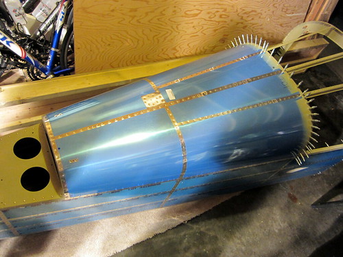
I quickly back-riveted the ELT antenna doubler on to the underside of the aft top skin, placed the A and B stiffeners onto the tail cone, then cleco'd the skin to the stiffeners and frames. I took a cue from Mark and Angela Lanier's project and only cleco'd on the horizontal top bits and let the skin stick striaght off to the sides. This allows my rivet bucker to access the underside of the top rivets without having to crawl inside.
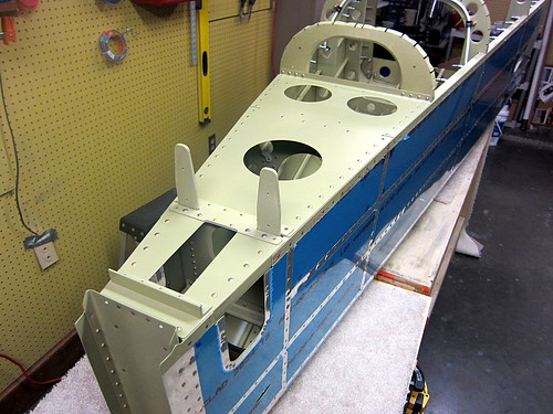
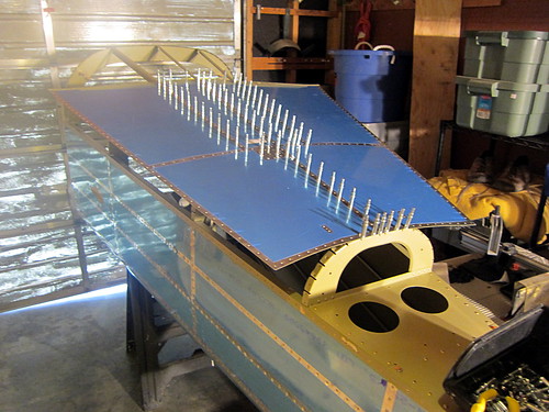
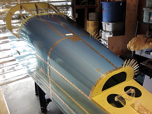
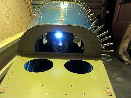
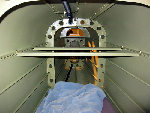
Jeremy and I made quick work of these rivets last night and this morning. From there, we bent one side down and cleco'd it in place, but left the other hanging. That way, we were able to do the entire left side without having to crawl inside. Having completed that and then bent and cleco'd the other side in place, the result looks like this:
By reaching in through the F-1009 hole (the D-shaped hole, above), we should be able to buck all of the rivets that attach the skin to the F-1009 frame, as well as the aft-most holes in the longeron. By reaching around past the front end of the skin, we should be able to do a bunch of the forward-most rivets in the longeron as well. This leaves only the curved portion on the right side of the F-1008 frame and a bit of the longeron that will need to be done from inside. First, I need to get some styrofoam cut up to make a platform so that Jeremy doesn't bend up the fragile bits inside the tail cone.
Today, somewhere along the left longeron of the tail cone, we put the 5000th rivet into the plane!
22 Jul 2010
I was originally thinking that we would buck the reachable rivets on the tail cone prior to having Jeremy crawling inside to get the unreachable ones. But after discussing it, we decided that he could do a better job from inside and there weren't all that many anyway. So I built up a platform of foam and blankets so that he wouldn't bend anything in there. I used some of the styrofoam that the came as packing material inside the empennage shipping crate for the base layer.
It was about an inch thick and this was high enough to get above the stiffeners. Above these pieces, I cut out some 2" pink foam blocks using a sawzall and this got the platform up above the level of the frame bottoms. On top of that I just layed a blanket down and that seemed to be enough. I'll save the foam pieces for any future need to get inside the tail cone.
Anyway, here's the requisite RV-10 construction photo of some poor sap squished inside the aft end of the tail cone:
We made quick work of the remaining 50 rivets and I think he was thankful to be out of there.
At that point, the rivets on the tail cone were essentially done (for now). The forward skin doesn't go on until the tail cone gets attached to the fuselage, and that's years away. So I turned my attention from rivets to the remaining internal accessories.
First up was the upper conduit. This conduit's aft terminus is at the F-1008 frame next to the static air T junction. I used the lightening hole wire tie anchor that I had riveted in earlier to wire tie the conduit in place. I hit it with a dab of black RTV to keep it all rigid.
The treatment at the F-1007 frame was essentially the same. Half way between the two frames I pop-riveted in the custom drop bracket I had fabricated earlier. From there, I attached an adel clamp to support the conduit. I used brass hardware because this adel clamp is right above where the magnetometers will eventually sit.
Forward of the F-1007 frame, the conduit remains incomplete since its drop bracket will get in the way of riveting on the forward ends of the A and B stiffeners under the forward top skin.
The second task to take care of was the rails for the magnetometer shelf. These were just a pair of angle aluminum bars that I had fabricated and primer earlier. I attached them to the bottom side of the longeron roughly half-way between the F-1007 and F-1008 frames and about 10 cm apart from each other. The attachment hardware was again all brass to keep any ferrous metal as far away from the magnetometers as possible.
The magnetometer platform that sits atop these rails will be fabricated later, when I know more about what the mounting requirements of the magnetometers are. So for now, this bit is done. In fact, this is the end of the tail cone chapter of the plans! Time to move on to the empennage attach chapter.
23 Jul 2010
With the tail cone mostly done, it was time to get started on attaching all of the subassemblies I had built to date together. The first step was to secure the horizontal stabilizer to the work benches with some woodscrews. From there, each of the elevators was attached to the horizontal stabilizers one at a time.
This was a tedious process because getting those two AN3 bolts through the rod-end bearings is a bit tricky and requires two people (at least in my setup). Once the two bolts are in place, you measure the clearance between the counterweight arm and the side of the horizontal stabilizer... then take the whole thing off again to make an adjustment to the rod-end bearing. Rinse, repeat. Then do the other elevator. Bit of a pain, but it when it was done, the results looked great!
Drilling the hole in the control horns for the central bearing was straightforward, and the AN4 bolt that connects both sides went through without a hitch. However, I have no idea how I'm going to thread washers into the gaps between the bearing and the horns. I suspect I need a new tool or something for that. I'm going to have to ask some of my builder friends what to do here.
Unfortunately I'm leaving town in a day or so for three weeks. So there will be another work-related RV-10 hiatus. :(
| <-- June 2010 | August 2010 --> |