| Workshop | Empennage | Wings | Fuselage | Contact |
| <-- March 2010 | May 2010 --> |
Chronological Updates, April, 2010
4 Apr 2010
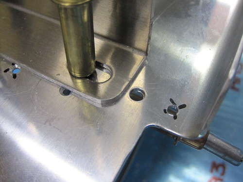
Did a short stint of work today on the Odyssey PC925 battery box. This part replaces the two battery tray side bars, the hold-down bar, and the two hold-down bolts of the RV-10 kit. Unfotunately, it doesn't match the hole pattern for the kit's side bars. I went ahead and lined up one hole (the front right one) just to save work. This kept the right-side holes aligned over the rib rail beneath the battery tray for support. However, the left-side holes were well inside of the left rib rail so they'll have less support. I started off by drilling a new #12 hole for the front-left battery box hole, then adding countersunk rivet holes for a K1000-3 nutplate on the bottom of the batter tray.
The forward-left corner becomes problematic. What was originally the forward-left hole for the battery tray side bar is now unused. But it is the only thing nearby that secures the battery tray to the rib rail underneath. So I'd really like to just put a bolt in there anyway. However, the hole is too close to the edge of the battery box to accept a bolt head.
I thought about making a shim that is the same thickness as the battery box flange and then bolting that down, but I think instead I'll just make part of the airframe ground bracket (which will eventually be attached in the blank area of the battery tray just forward of the battery box) stick out over this spot and act as a shim. Either way, both the new and the old battery hold-down holes will have bolts in them.
Turning to the aft end of the battery box, we have even more problems.
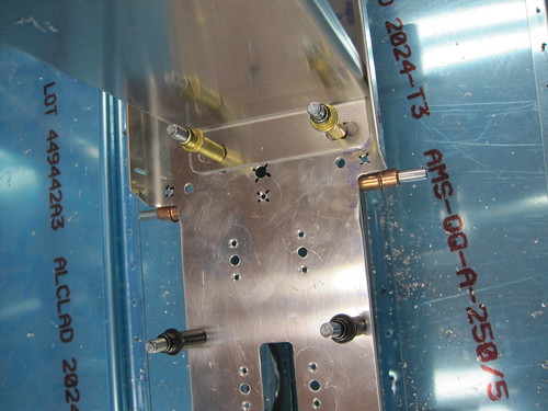
First, the aft-left hole required a new set of nutplate holes which are also not supported by the rib rail. Again, the existing hole is now too close to the box to accept a bolt directly (though in this case filing down the corner of the box may suffice). The bigger problem is on the aft-right side, where the new hole through the battery tray and the rib rail beneath is too close to the existing nutplate rivet hole for the old side bar hole.
I'll have to add a nutplate for this hole that only has one lug, and I don't have any of those in the correct size. So that bit is on hold awaiting more parts.
Actually, everything is now on hold awaiting more parts. I spent a bit of time this evening thinking about exactly what I need to finish all of the accessories mounting in the tail cone, and came up with a big list of hardware, tools, and parts that I needed to buy. $180 later, I'm now on hold. And it probably won't arrive before I'm off galavanting around the world again next week. So this may be the sum total of the work that gets done on the plane in April. Oh well... slow progress is still progress.
1 Apr 2010
No, it's no April Fool's joke, I actually found time to do more work on the plane!
I spent a lot of time while I was out of the country doing some planning for the tail cone accessories and the steps required to install each. Tonight I put those steps in a sensible order, and drew a line on each list at the point where I would need to disassemble the tail cone before continuing. Everything above that line is now on the critical path. This evening I spent some time getting the elevator trim servo bracket assembly and static air system lists down to the disassembly-required line.
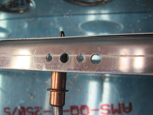
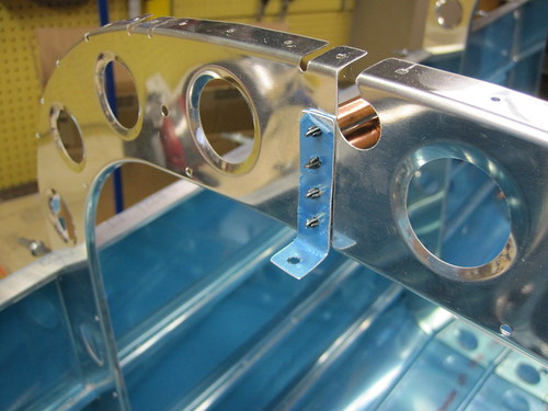
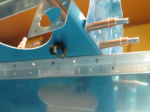
First, I fabricated a small bracket that sits aft of the rivet line that attaches the two halves of the frame that sits just aft of the static airports. This bracket will support the T-junction that joins the two sides of the static air system. Here it is cleco'd to the frame:
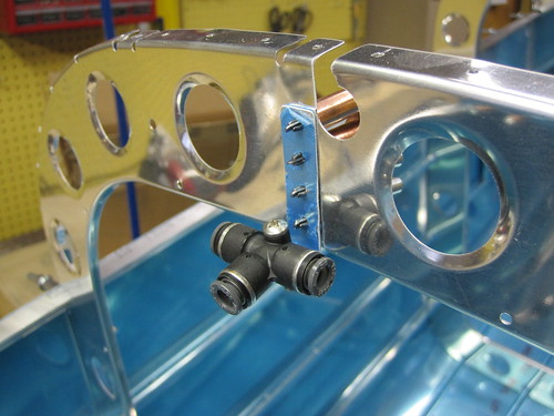
I discovered that if I put the 90° elbows coming right off the static ports facing aft, they poke right through the lightening holes in the frame. This allows me to plumb all of the static line and associated clamp hardware to the aft of the frame. This, in turn, keeps all of it out of the way of the skin rivets associated with the frame, which are all on the front side. That means that I can go ahead and run the static lines up as far as the T junction before riveting on the top skin, preventing me from having to crawl inside the dark enclosed tail cone to do it later. Here is a picture of the T-junction temporarily installed on its bracket:
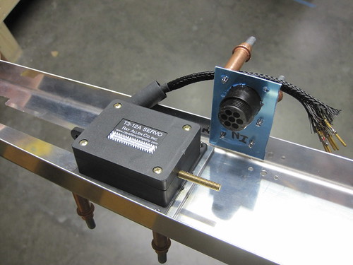
Next, I fabricated a little drop plate to hang off the side of the elevator trim servo bracket. It holds a panel-mount circular plastic connector for the five servo control and sense wires.
With it fabricated, the elevator trim servo bracket parts are all ready for priming. One more small modification regarding elevator trim was to add a hole in the aft deck for an Adel clamp on the bottom face of the deck. This clamp will be the last support for the cable that will eventually connect to to the CPC in the drop plate.
The only other thing I did tonight was to mark some hole positions on the F-1028 channel for Adel clamps that will hold the top conduit on one side and the wire bundle coming out of the overhead console on the other. After marking the holes, this section was ready for disassembly as well and was moved off the critical path list.
Accessory assemblies still on the list of things to do before disassembly:
Did a short stint of work today on the Odyssey PC925 battery box. This part replaces the two battery tray side bars, the hold-down bar, and the two hold-down bolts of the RV-10 kit. Unfotunately, it doesn't match the hole pattern for the kit's side bars. I went ahead and lined up one hole (the front right one) just to save work. This kept the right-side holes aligned over the rib rail beneath the battery tray for support. However, the left-side holes were well inside of the left rib rail so they'll have less support. I started off by drilling a new #12 hole for the front-left battery box hole, then adding countersunk rivet holes for a K1000-3 nutplate on the bottom of the batter tray.
The forward-left corner becomes problematic. What was originally the forward-left hole for the battery tray side bar is now unused. But it is the only thing nearby that secures the battery tray to the rib rail underneath. So I'd really like to just put a bolt in there anyway. However, the hole is too close to the edge of the battery box to accept a bolt head.
I thought about making a shim that is the same thickness as the battery box flange and then bolting that down, but I think instead I'll just make part of the airframe ground bracket (which will eventually be attached in the blank area of the battery tray just forward of the battery box) stick out over this spot and act as a shim. Either way, both the new and the old battery hold-down holes will have bolts in them.
Turning to the aft end of the battery box, we have even more problems.
First, the aft-left hole required a new set of nutplate holes which are also not supported by the rib rail. Again, the existing hole is now too close to the box to accept a bolt directly (though in this case filing down the corner of the box may suffice). The bigger problem is on the aft-right side, where the new hole through the battery tray and the rib rail beneath is too close to the existing nutplate rivet hole for the old side bar hole.
I'll have to add a nutplate for this hole that only has one lug, and I don't have any of those in the correct size. So that bit is on hold awaiting more parts.
Actually, everything is now on hold awaiting more parts. I spent a bit of time this evening thinking about exactly what I need to finish all of the accessories mounting in the tail cone, and came up with a big list of hardware, tools, and parts that I needed to buy. $180 later, I'm now on hold. And it probably won't arrive before I'm off galavanting around the world again next week. So this may be the sum total of the work that gets done on the plane in April. Oh well... slow progress is still progress.
1 Apr 2010
No, it's no April Fool's joke, I actually found time to do more work on the plane!
I spent a lot of time while I was out of the country doing some planning for the tail cone accessories and the steps required to install each. Tonight I put those steps in a sensible order, and drew a line on each list at the point where I would need to disassemble the tail cone before continuing. Everything above that line is now on the critical path. This evening I spent some time getting the elevator trim servo bracket assembly and static air system lists down to the disassembly-required line.
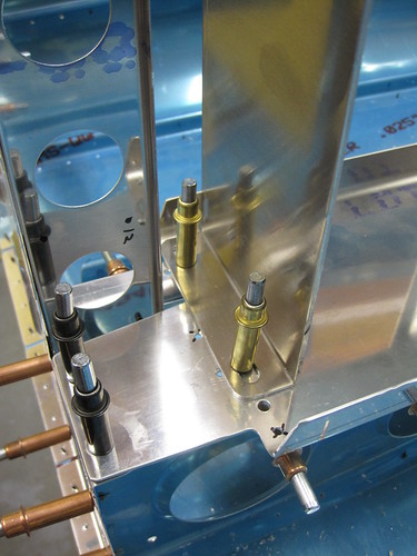
First, I fabricated a small bracket that sits aft of the rivet line that attaches the two halves of the frame that sits just aft of the static airports. This bracket will support the T-junction that joins the two sides of the static air system. Here it is cleco'd to the frame:
I discovered that if I put the 90° elbows coming right off the static ports facing aft, they poke right through the lightening holes in the frame. This allows me to plumb all of the static line and associated clamp hardware to the aft of the frame. This, in turn, keeps all of it out of the way of the skin rivets associated with the frame, which are all on the front side. That means that I can go ahead and run the static lines up as far as the T junction before riveting on the top skin, preventing me from having to crawl inside the dark enclosed tail cone to do it later. Here is a picture of the T-junction temporarily installed on its bracket:
Next, I fabricated a little drop plate to hang off the side of the elevator trim servo bracket. It holds a panel-mount circular plastic connector for the five servo control and sense wires.
With it fabricated, the elevator trim servo bracket parts are all ready for priming. One more small modification regarding elevator trim was to add a hole in the aft deck for an Adel clamp on the bottom face of the deck. This clamp will be the last support for the cable that will eventually connect to to the CPC in the drop plate.
The only other thing I did tonight was to mark some hole positions on the F-1028 channel for Adel clamps that will hold the top conduit on one side and the wire bundle coming out of the overhead console on the other. After marking the holes, this section was ready for disassembly as well and was moved off the critical path list.
Accessory assemblies still on the list of things to do before disassembly:
- Top wiring conduit
- Bottom wiring conduit
- Airframe grounding bracket
- Main battery box
- Main battery contactor
- External power contactor
- Magnetometer shelf
- Oxygen tank
- Oxygen distribution manifold
- ELT
- ELT antenna
- NACA ventilation inlets
| <-- March 2010 | May 2010 --> |