
| Workshop | Empennage | Wings | Fuselage | Contact |
| <-- January 2010 | March 2010 --> |
Chronological Updates, February, 2010
8 Feb 2010
A bit of work has occurred in the last week. First, Bob came by on a lunch break and we did the 120 bottom side forward spar skin rivets. The next day, my replacement countersink/deburring bit arrived from Cleaveland so I finished off the K1000-3 anchor nuts for the bonding strap attachments. Here's the aft view of one of the two:
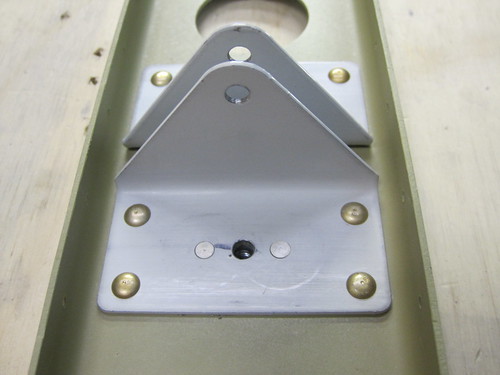
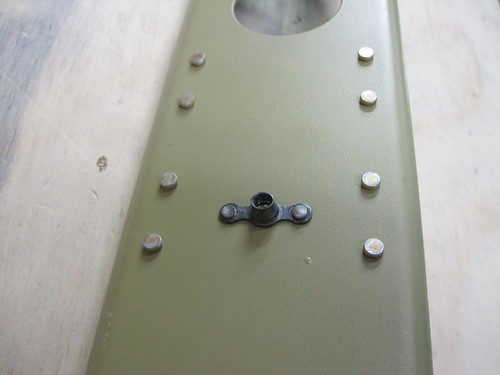
And here is the forward view:
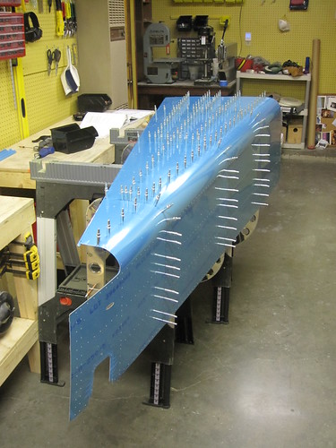
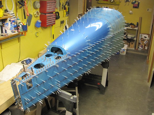
With that, the rear spar customiziations are complete and it is ready to be riveted onto the rest of the horizontal stabilizer. However, before that can happen, I need to finish all of the inspar and stringer rivets. And I wanted help with that. I've been trying to get an assistant for several days now, and finally this evening Bob was free again and we spent three hours tonight knocking out all of the remaining bucked rivets in the horizontal stab. We did 384 rivets tonight, and at some point we put in the 3000th rivet in the plane!
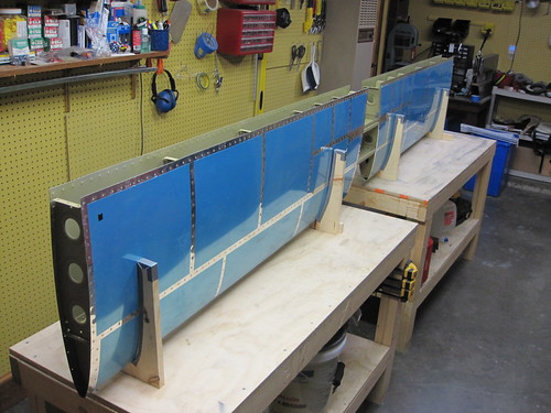
As you can see in that picture, I also finished off the squeezed inner and outer inspar rib flange rivets, so now the only rivets left are those attaching the rear spar. One more thing before I squeeze those rivets, though, and that is to spray some krylon primer into the inspar area because there are a fair amount of scratches in the akzo from the bucking of all those rivets. This won't take any time, though. In all likelihood, I'll be done with the horizontal stabilizer tomorrow!
9 Feb 2010
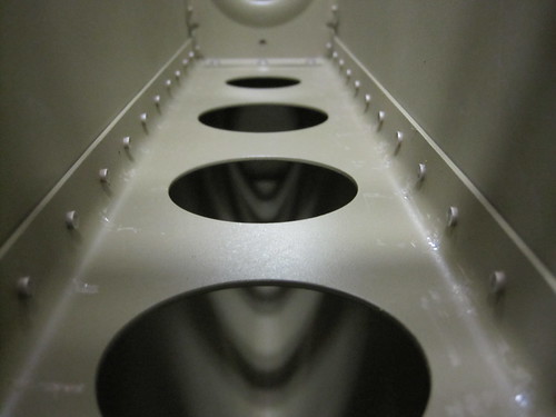
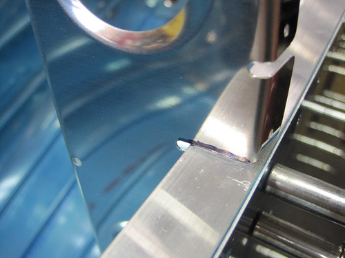
When I got home from work, I drilled out the one rivet that Bob and I missed last night and replaced it with a minute of bucking help from Mike. Inspecting the inside surfaces of the horizontal stabilizer before closing up the aft end for good, I decided that there was just too much damage to the Akzo coating from the bucking bar. Some parts were really scratched up. Here is a particularly bad example:
I took a can of Krylon grey primer spray paint and hit all of the rivet lines on the inside of the stabilizer just to be sure everything had some anti-corrosion coating. Having done that, there was nothing left to do but to rivet on the rear spar. I cleco'd it into place:
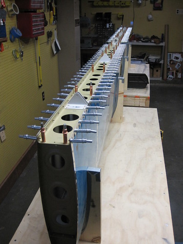
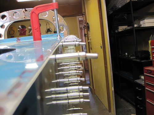
Then I set about riveting all of the spar web rivets (the 1/8" holes on the aft face). Unfortunately, my kit seems to be five short on the LP4-3 blind rivets, so I wasn't able to quite finish. I left five clecos in and spread them out so that each rib had at least one rivet in it. Then I went ahead and squeezed all 252 flange rivets that connect the rear spar to the skins. A total of 289 rivets on the day, but they were all squeezable so they went quickly and required no assistance. Here you can see the result, with the five clecos still sticking out of the aft spar:
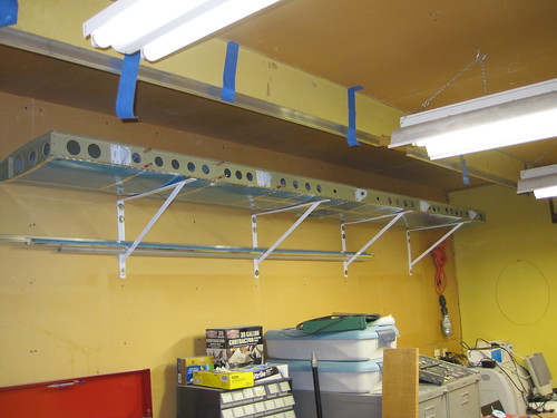
I went ahead and stuck the more-or-less completed horizontal stabilizer on some shelf brackets I had hung just for this purpose, with the rear spar facing outward. This will allow me to pop in those last five rivets when I get some more without having to take the stabilizer down.
Though it's technically not "done," there's only about a minute of work left on it. Onward to the tail cone!
13 Feb 2010
I've been slowly beginning to work on the tail cone for a couple weeks now. Even before I finished riveting the skins onto the horizontal stabilizer I was sneaking in a bit of work on the tail cone frames while waiting for someone that could help me buck rivets.
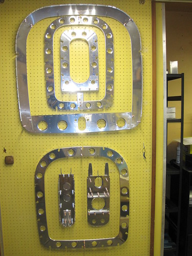
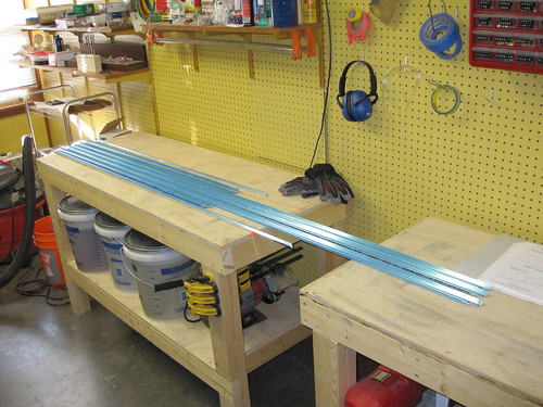
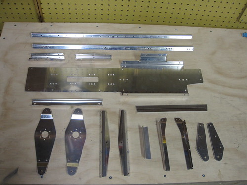
The three frames (the largest of the six pieces show above) are trivial to get to this stage; they just need the edges deburred and a handfull of holes match drilled. The three bulkheads each have a few custom-fabricated pieces, mostly just angle aluminum or J-stiffener stock cut to particular lengths and holes drilled. The extruded aluminum tie down block requires the hole to be tapped, but after seeing that Cleaveland Tools was offering a pre-tapped block for less money than it would cost me to buy the tap set... I just bought theirs.
The next step was to cut the J-stiffeners to length, which was going fine until I broke my bandsaw. This set me back almost a week in time. While I was figuring out how to go about fixing it, I went ahead and cut the 45° bevels at the ends of the J-stiffeners. Unfortunately, the first two I did I didn't pay enough attention to the plans and cut wrong. Instead of starting the 45° cut at the inner edge of the flat part of the J-stiffener, I started it at the outer corner. In doing so, I made it impossible for the end rivet on both ends to find purchase. I trimmed the points off and fixed them up, but now they're too short by two widths of the flat part (a bit less than an inch). It's only the -F stiffeners, the ones that go next to the bellcrank ribs on the bottom skin, and I think I can actually get away with them being one rivet short; there's going to be a lot of extra stiffening in that area anyway when I add extra ribs for my oxygen system, pitch autopilot servo, and external power socket. We'll see, but I think I can avoid re-ordering those two 6' long pieces.
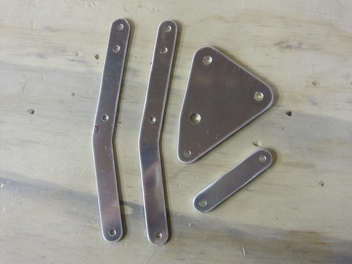
While I was trying to decide what to do about the two short stiffeners and not having a bandsaw to continue on with the first part of the longeron fabrication, I skipped ahead to the elevator trim servo mount. This is actually in the chapter on assembling the empennage for some reason, but I wanted to prime these parts along with the rest of the tail cone bits, so I'm doing it now.

Above you can see the elevator trim control cable mount brackets (with the big round holes) and the elevator trim bellcrank brackets that I bought from iflyrv10.com. I discovered that the servo mount holes require a #28 drill which I do not have, so I ordered one from Cleaveland and now this part is also on hold.
In the meantime, I drilled out the holes and deburred the edges of the trim servo linkage and bellcrank plate:
Today, I set about fixing my bandsaw—it turned out to be a problem with the upper wheel tilt adjustment that was causing the blade to ride off the edge of the wheels. With the bandsaw back in operation, I could finally cut the longerons to length. Having done that, and cut the little notch for the horizontal stabilizer attachment bars, I got to confront the first "bend this slightly until it fits" step in the construction of the RV-10.
The side skins of the tail cone have a 2° bend in the top edge about 20" forward of their aft end. The longerons run parallel to the top edge of this skin, including the 2° bend. So I had to put the angle aluminum in a vice, preload it, and bang on the angle with a dead blow hammer until it laid on the skin just right:
When I was happy with that placement, I stowed the longerons and the side skins and started on the initial assembly of the tail cone! I extended my adjustable saw horses up to their full height of 39" (this step requires at least 38") and laid the bottom skin upside down on top of the saw horses. The middle three frames and bulkhead were attached with clecos without any problem.
The next step is to slide in the two J-stiffeners that are too short. This will be where I get to see whether or not I need to re-order them. But first I'm waiting on a edge marking block from Aircraft Spruce to arrive so that I can accurately draw the rivet line down the bottom side of all the J-stiffeners.
So between the #28 drill bit and the edge marking block, I am now totally on hold awaiting arrival of tools. Though they've already been ordered, they are unfortunately not arriving until the end of this coming week. So progress will be a bit slow. Also, it looks like I might have to go overseas for a few weeks for work, and that'll make shop work difficult as well...
In the interrum, I've disassembled what you see in the picture above to dissuade my cats from jumping up on it and bending the skin all the crap. Once I get the stiffeners in there it shouln't be a problem... I hope.
17 Feb 2010
Today I got a package from Cleaveland that included the #28 bit I was missing (and a 1/4" drive torque wrench with slightly lower torques than the monster torque wrench I already had). Also got a package from Aircraft Spruce with my edge marking block in it. These were the two things I had been waiting for for the last few days and were stalling forward progress along the critical path.
In the meantime, while waiting for these packages, I have spent a couple hours in the last couple days fabricating some get-ahead parts that could be done out of sequence.
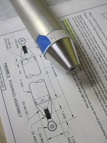
I finished pretty much all of the battery tray and its accessories as well as the elevator bellcrank assembly. I also skipped ahead to the empennage assembly chapter again and cranked out the two spacers that sit between the HS-1008 brackets and the tail cone aft deck, as well as the entire elevator pushrod assembly. Here's the template I made out of a piece of notebook paper and some tape:
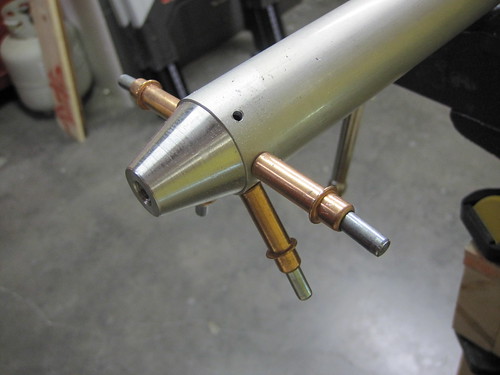
And here is the holes in the process of match-drilling:
When I got home from work today and the tools were there, I got right to work on the tail cone critical path again. The first thing to do was to use the edge marking block to put a rivet centerline down the face of each of the J-stiffeners. I also used it to mark the end rivet crosshair. These marks allowed me to align the stiffeners for match drilling.
First, I had to re-assemble the bottom skin and frams on the saw horses which I had taken down for cat protection. With that done, the first stiffeners to get match-drilled to the bottom skin are the F-1047F pair—the pair that I cut an inch too short. I did a lot of thinking over the last two days about whether I needed to re-make these two parts and I decided that I don't. I'm going to add two more whole ribs for the oxygen tank mount, as well as some additional structure for the external power socket. These should more than make up for the one missing rivet in each of the two -F stiffeners.
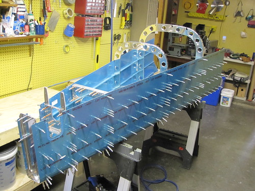
Since my added structure will all be at the forward end of the tail cone, I decided to have the missing rivet be at that end, so I matched the crosshairs up at the aft end rather than the forward as called for in the plans. With the two -F stiffeners in place and match drilled, I added the central -G stiffener and got it match drilled as well. Finally, I cleco'd in the two bellcrank ribs and match-drilled them to the frame at their aft end. Then I hung the left-side -C, -D, and -E stuffeners into the recesses in the frames in preparation for hanging the first side skin. Here's what that looked like:
From that point, it was a quick job to hang the left-side skin in place and cleco it to the aft skin and the frames.
It was a bummer to discover that once I had gotten this far that it was bedtime and I needed to quit. Having these two skins at right angles to each other begins to define a real volume of a large component of the plane. It's starting to look like a substantial plane in my workshop! This is very exciting and I didn't want to stop. But if I don't go to work, I won't be able to afford the rest of the plane. So I called it a night.
20 Feb 2010
The last couple days have seen the tailcone structure come together very rapidly. Thursday I had an EAA meeting down in Santa Fe that ran late (awesome presentation from the founder of Vertical Power who gave us a sneak-preview of a new product they're about to release that I think is an instant buy for me), so I didn't get any work done, but yesterday and this morning I did a lot.
For starters, I match-drilled all of the left-side stiffeners that were just hanging in the frames at the end of my last post. No real change in appearance other than a bunch more clecos, so I'll forego linking to the picture. Next I had to roll the whole assembly over 90° so that the left side skin was down. This gave me access to the right-side area, making attachment of the second side skin easier. Picking the whole tailcone up with its ~350 or so clecos in it was a challenge. It's not heavy to the point where one person can't handle it, but it is awfully akward, and trying to set it down on two narrow saw horses without bending a cleco under the skin was challenging.
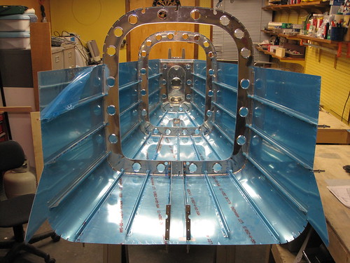
With the tailcone reoriented, I set about attaching the two aft bulkheads and the little tiny aft bottom skin piece between them. This turned out to be a huge pain somehow. I was expecting it to be a really quick thing, but it took easily an hour. I had to take all three parts off repeatedly and try adding clecos from a new starting point before I finally landed on an order that made the holes line up properly. I cleco'd down from the top of the forward bulkhead (the one with the two horizontal stabilizer attach bars sticking up out of it), down to the point where the aft bottom skin rivet line joins it. Then I did the aft bottom skin rivet line, then worked the curves across the botom of the tail, around to the other side. I also had to file down a couple of the flange tabs in order to get them to bend into place properly. The aft bulkhead was considerably easier, thank goodness.
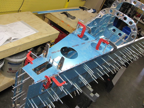
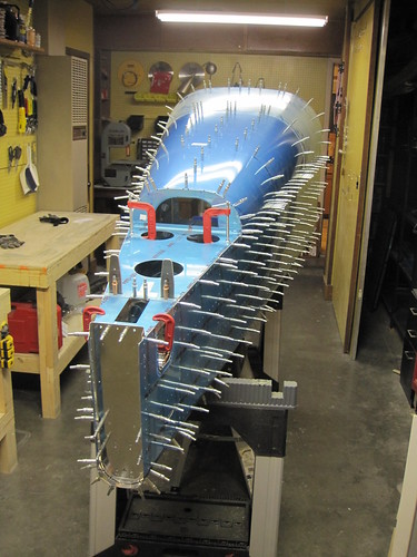
With this seemingly trivial task finally out of the way, I got the three right-side stiffeners set into their cutouts in the frames and bulkheads, then layed the second skin down and cleco'd it to the frames. Once more, I rolled the whole tail over, this time so that the bottom skin was down. This made it look like I had half a canoe in my shop.
Getting all three stiffeners match-drilled was straightforward if a bit tedious. Took about an hour.
The next step was to install the rudder stop bracing. The custom-cut angle aluminum piece that was fabricated earlier turned out to be just a tad narrower than I'd like; one of the holes match-drilled in from the aft face of the aft bulkhead ended up being really close to the edge. I'd recommend making this piece a bit longer than advertised in the plans. Measure it off the forward face of the aft bulkhead.
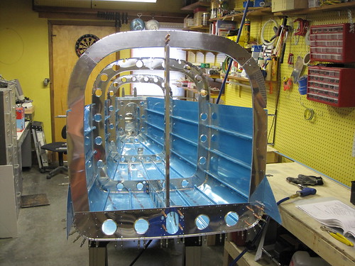
Next came the attachment of the F-1006 frame, the huge one at the front of the tail cone. This thing is the interface between the tail cone, fuselage, and the fiberglass cabin top, so none of the outer holes get match drilled for a long time. But it provides structure for the top skins which do need to be installed soon, and it also gets attached to the bellcrank ribs, and that match-drilling happens now.
Speaking of the bellcrank ribs, I attached the rails to the top as well.
Next, the attention turned to the aft end. I was somewhat dreading putting the longerons in place, because I wasn't sure how accurate my bend had been, whether the notches would line up right with the horizontal stabilizer attachment bars, etc. But it turned out to fit perfectly. They snapped right into place with no problems at all. The F-1011 spacer that sits on top of one of the bulkheads needed some double-sided tape, and I didn't have enough clamps for the aft decking, so I made a quick trip to the hardware store. $18 and 20 minutes later I had this:
Very little manipulation was required to get the longerons to line up with the skin and deck edges the way they are meant to, and this was a relief. Unfortunately, it turns out that I'm an idiot and I didn't check that I had the requisite drill bit for drilling all of the skin/longeron holes (3/32"). Not an uncommon size, so I can see why I might have overlooked it... but that's the one drill bit of my set that had a broken tip and I tossed it last week. Great. So I need to go back to the hardware store, but I think I'll take a break for awhile first.
21 Feb 2010
Was out of town yesterday evening and half of today, but when I got back I got some more good progress done on the initial assembly of the tail cone parts. On my way back into town, I grabbed a pair of new 3/32" drill bits which allowed me to proceed with the longeron drilling.
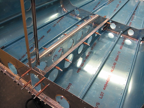
Doing the two rows of about 100 rivets took an hour and a half, with lots of clamp moving involved to ensure that the top of the skin lined up exactly with the top edge of the longerons. I encountered a problem with the middle two frames: the longeron cutout was a bit too low, and the frames weren't able to slide all the way out on the longeron as a result. The flanges closest to the longerons therefore were too far away and the holes didn't line up right.
I've decided I'm going to just match drill those holes next time I assemble the tail, and skip ahead to everything else for now. When I disassemble those frames, I'll file the offending bits off of the frames (marked in the black in the picture, above).
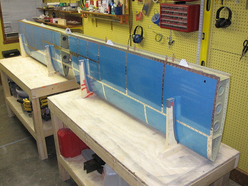
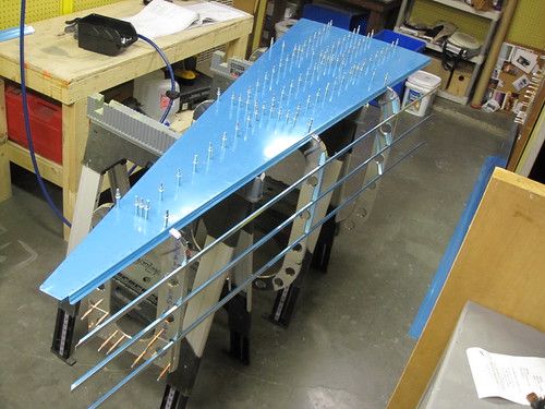
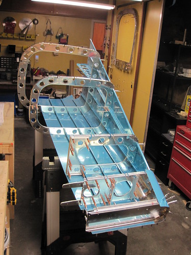
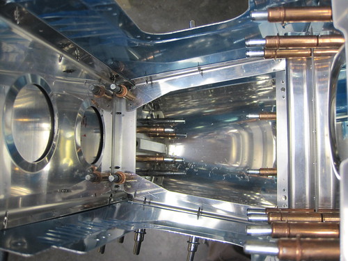
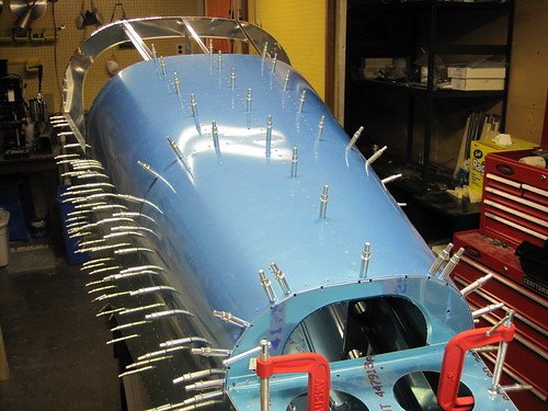
With the longerons done, work proceeded quickly getting the F-1009 mounted, the top stiffeners, and finally the two top skins. Here's the aft skin in place with the aft halves of the stiffeners match drilled:
And here is the forward top skin in place as well:
The matched holes feature of the Van's kits is a godsend; this would be such a huge pain if the holes didn't just magically line up. These skins are tight. It's like a giant drum.
I didn't finish match-drilling the stiffeners; I'm going to leave that for another night. This thing i huge, by the way, and really fills up my entire shop. Its overwhelming presence in the shop just acts as a huge motivator to keep working. I can't ignore it! :-D But for tonight I have to call it quits.
22 Feb 2010
Just a couple hours of work today, beginning with the completion of the match drilling of the top three stiffeners. After that, I drilled out the #30 holes connecting the aft deck to the longerons below:
Then I added the two custom-fabricated pieces of angle aluminum that I bought from iflyrv10.com. The support for the horizontal stabilizer attachment bars goes here:

The up elevator stop bracket goes here:
I spent some time looking ahead in the plans to find out what happened next with the access panels at the aft ends of the tail cone sides; turns out they don't get their top holes drilled until during the fitting of the empennage fairing, which doesn't get delivered until the fuselage kit! So I went ahead and drilled, deburred, and dimpled the four existing holes. These two parts go into the (currently very small) pile that is ready for primer!
I also went ahead to the empennage attach chapter of the plans and completed the fabrication steps there. The elevator pushrod was already complete and ready for primer; now the elevator trim servo mount is also complete. I cleco'd it into place under the aft deck because it is going to get a couple custom pieces added to it before it will be ready for primer.
Specifically, there will be a small tab that hangs down from the left side and holds a CPC panel mount recepticle for the servo wires.
With that, tail cone initial fabrication was complete! The next step in the plans is to disassemble the entire thing and begin the dreaded deburring process.
However, before I disassemble the structure, I want to add all the miscellaneous bits and pieces that will support the various custom hardware gizmos to be mounted in the tail. A not-necessarily complete list includes:
This is almost guaranteed to be a long time coming since I don't even have any of the above listed accessories yet other than the conduit and NACA inlets (though I do have the static system, ELT, ELT antenna, and the external power receptacle on order). I've got a bunch of gear to buy still, obviously. Add to this that I'm about to be deployed overseas for work for probably the bulk of March, and the RV-10 project is clearly about to go from rapid progress to a standstill for some time. But that's OK, in the meantime I've got an awesome-looking tail cone filling up my shop. Definitely still highly motivated!
A bit of work has occurred in the last week. First, Bob came by on a lunch break and we did the 120 bottom side forward spar skin rivets. The next day, my replacement countersink/deburring bit arrived from Cleaveland so I finished off the K1000-3 anchor nuts for the bonding strap attachments. Here's the aft view of one of the two:
And here is the forward view:
With that, the rear spar customiziations are complete and it is ready to be riveted onto the rest of the horizontal stabilizer. However, before that can happen, I need to finish all of the inspar and stringer rivets. And I wanted help with that. I've been trying to get an assistant for several days now, and finally this evening Bob was free again and we spent three hours tonight knocking out all of the remaining bucked rivets in the horizontal stab. We did 384 rivets tonight, and at some point we put in the 3000th rivet in the plane!
As you can see in that picture, I also finished off the squeezed inner and outer inspar rib flange rivets, so now the only rivets left are those attaching the rear spar. One more thing before I squeeze those rivets, though, and that is to spray some krylon primer into the inspar area because there are a fair amount of scratches in the akzo from the bucking of all those rivets. This won't take any time, though. In all likelihood, I'll be done with the horizontal stabilizer tomorrow!
9 Feb 2010
When I got home from work, I drilled out the one rivet that Bob and I missed last night and replaced it with a minute of bucking help from Mike. Inspecting the inside surfaces of the horizontal stabilizer before closing up the aft end for good, I decided that there was just too much damage to the Akzo coating from the bucking bar. Some parts were really scratched up. Here is a particularly bad example:
I took a can of Krylon grey primer spray paint and hit all of the rivet lines on the inside of the stabilizer just to be sure everything had some anti-corrosion coating. Having done that, there was nothing left to do but to rivet on the rear spar. I cleco'd it into place:
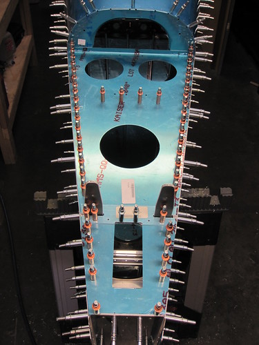
Then I set about riveting all of the spar web rivets (the 1/8" holes on the aft face). Unfortunately, my kit seems to be five short on the LP4-3 blind rivets, so I wasn't able to quite finish. I left five clecos in and spread them out so that each rib had at least one rivet in it. Then I went ahead and squeezed all 252 flange rivets that connect the rear spar to the skins. A total of 289 rivets on the day, but they were all squeezable so they went quickly and required no assistance. Here you can see the result, with the five clecos still sticking out of the aft spar:
I went ahead and stuck the more-or-less completed horizontal stabilizer on some shelf brackets I had hung just for this purpose, with the rear spar facing outward. This will allow me to pop in those last five rivets when I get some more without having to take the stabilizer down.
Though it's technically not "done," there's only about a minute of work left on it. Onward to the tail cone!
13 Feb 2010
I've been slowly beginning to work on the tail cone for a couple weeks now. Even before I finished riveting the skins onto the horizontal stabilizer I was sneaking in a bit of work on the tail cone frames while waiting for someone that could help me buck rivets.
The three frames (the largest of the six pieces show above) are trivial to get to this stage; they just need the edges deburred and a handfull of holes match drilled. The three bulkheads each have a few custom-fabricated pieces, mostly just angle aluminum or J-stiffener stock cut to particular lengths and holes drilled. The extruded aluminum tie down block requires the hole to be tapped, but after seeing that Cleaveland Tools was offering a pre-tapped block for less money than it would cost me to buy the tap set... I just bought theirs.
The next step was to cut the J-stiffeners to length, which was going fine until I broke my bandsaw. This set me back almost a week in time. While I was figuring out how to go about fixing it, I went ahead and cut the 45° bevels at the ends of the J-stiffeners. Unfortunately, the first two I did I didn't pay enough attention to the plans and cut wrong. Instead of starting the 45° cut at the inner edge of the flat part of the J-stiffener, I started it at the outer corner. In doing so, I made it impossible for the end rivet on both ends to find purchase. I trimmed the points off and fixed them up, but now they're too short by two widths of the flat part (a bit less than an inch). It's only the -F stiffeners, the ones that go next to the bellcrank ribs on the bottom skin, and I think I can actually get away with them being one rivet short; there's going to be a lot of extra stiffening in that area anyway when I add extra ribs for my oxygen system, pitch autopilot servo, and external power socket. We'll see, but I think I can avoid re-ordering those two 6' long pieces.
While I was trying to decide what to do about the two short stiffeners and not having a bandsaw to continue on with the first part of the longeron fabrication, I skipped ahead to the elevator trim servo mount. This is actually in the chapter on assembling the empennage for some reason, but I wanted to prime these parts along with the rest of the tail cone bits, so I'm doing it now.
Above you can see the elevator trim control cable mount brackets (with the big round holes) and the elevator trim bellcrank brackets that I bought from iflyrv10.com. I discovered that the servo mount holes require a #28 drill which I do not have, so I ordered one from Cleaveland and now this part is also on hold.
In the meantime, I drilled out the holes and deburred the edges of the trim servo linkage and bellcrank plate:
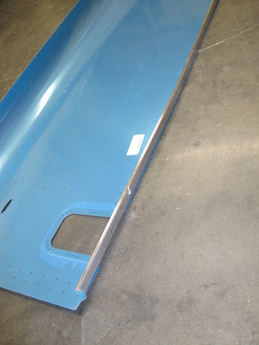
Today, I set about fixing my bandsaw—it turned out to be a problem with the upper wheel tilt adjustment that was causing the blade to ride off the edge of the wheels. With the bandsaw back in operation, I could finally cut the longerons to length. Having done that, and cut the little notch for the horizontal stabilizer attachment bars, I got to confront the first "bend this slightly until it fits" step in the construction of the RV-10.
The side skins of the tail cone have a 2° bend in the top edge about 20" forward of their aft end. The longerons run parallel to the top edge of this skin, including the 2° bend. So I had to put the angle aluminum in a vice, preload it, and bang on the angle with a dead blow hammer until it laid on the skin just right:
When I was happy with that placement, I stowed the longerons and the side skins and started on the initial assembly of the tail cone! I extended my adjustable saw horses up to their full height of 39" (this step requires at least 38") and laid the bottom skin upside down on top of the saw horses. The middle three frames and bulkhead were attached with clecos without any problem.
The next step is to slide in the two J-stiffeners that are too short. This will be where I get to see whether or not I need to re-order them. But first I'm waiting on a edge marking block from Aircraft Spruce to arrive so that I can accurately draw the rivet line down the bottom side of all the J-stiffeners.
So between the #28 drill bit and the edge marking block, I am now totally on hold awaiting arrival of tools. Though they've already been ordered, they are unfortunately not arriving until the end of this coming week. So progress will be a bit slow. Also, it looks like I might have to go overseas for a few weeks for work, and that'll make shop work difficult as well...
In the interrum, I've disassembled what you see in the picture above to dissuade my cats from jumping up on it and bending the skin all the crap. Once I get the stiffeners in there it shouln't be a problem... I hope.
17 Feb 2010
Today I got a package from Cleaveland that included the #28 bit I was missing (and a 1/4" drive torque wrench with slightly lower torques than the monster torque wrench I already had). Also got a package from Aircraft Spruce with my edge marking block in it. These were the two things I had been waiting for for the last few days and were stalling forward progress along the critical path.
In the meantime, while waiting for these packages, I have spent a couple hours in the last couple days fabricating some get-ahead parts that could be done out of sequence.
I finished pretty much all of the battery tray and its accessories as well as the elevator bellcrank assembly. I also skipped ahead to the empennage assembly chapter again and cranked out the two spacers that sit between the HS-1008 brackets and the tail cone aft deck, as well as the entire elevator pushrod assembly. Here's the template I made out of a piece of notebook paper and some tape:
And here is the holes in the process of match-drilling:
When I got home from work today and the tools were there, I got right to work on the tail cone critical path again. The first thing to do was to use the edge marking block to put a rivet centerline down the face of each of the J-stiffeners. I also used it to mark the end rivet crosshair. These marks allowed me to align the stiffeners for match drilling.
First, I had to re-assemble the bottom skin and frams on the saw horses which I had taken down for cat protection. With that done, the first stiffeners to get match-drilled to the bottom skin are the F-1047F pair—the pair that I cut an inch too short. I did a lot of thinking over the last two days about whether I needed to re-make these two parts and I decided that I don't. I'm going to add two more whole ribs for the oxygen tank mount, as well as some additional structure for the external power socket. These should more than make up for the one missing rivet in each of the two -F stiffeners.
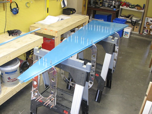
Since my added structure will all be at the forward end of the tail cone, I decided to have the missing rivet be at that end, so I matched the crosshairs up at the aft end rather than the forward as called for in the plans. With the two -F stiffeners in place and match drilled, I added the central -G stiffener and got it match drilled as well. Finally, I cleco'd in the two bellcrank ribs and match-drilled them to the frame at their aft end. Then I hung the left-side -C, -D, and -E stuffeners into the recesses in the frames in preparation for hanging the first side skin. Here's what that looked like:
From that point, it was a quick job to hang the left-side skin in place and cleco it to the aft skin and the frames.
It was a bummer to discover that once I had gotten this far that it was bedtime and I needed to quit. Having these two skins at right angles to each other begins to define a real volume of a large component of the plane. It's starting to look like a substantial plane in my workshop! This is very exciting and I didn't want to stop. But if I don't go to work, I won't be able to afford the rest of the plane. So I called it a night.
20 Feb 2010
The last couple days have seen the tailcone structure come together very rapidly. Thursday I had an EAA meeting down in Santa Fe that ran late (awesome presentation from the founder of Vertical Power who gave us a sneak-preview of a new product they're about to release that I think is an instant buy for me), so I didn't get any work done, but yesterday and this morning I did a lot.
For starters, I match-drilled all of the left-side stiffeners that were just hanging in the frames at the end of my last post. No real change in appearance other than a bunch more clecos, so I'll forego linking to the picture. Next I had to roll the whole assembly over 90° so that the left side skin was down. This gave me access to the right-side area, making attachment of the second side skin easier. Picking the whole tailcone up with its ~350 or so clecos in it was a challenge. It's not heavy to the point where one person can't handle it, but it is awfully akward, and trying to set it down on two narrow saw horses without bending a cleco under the skin was challenging.
With the tailcone reoriented, I set about attaching the two aft bulkheads and the little tiny aft bottom skin piece between them. This turned out to be a huge pain somehow. I was expecting it to be a really quick thing, but it took easily an hour. I had to take all three parts off repeatedly and try adding clecos from a new starting point before I finally landed on an order that made the holes line up properly. I cleco'd down from the top of the forward bulkhead (the one with the two horizontal stabilizer attach bars sticking up out of it), down to the point where the aft bottom skin rivet line joins it. Then I did the aft bottom skin rivet line, then worked the curves across the botom of the tail, around to the other side. I also had to file down a couple of the flange tabs in order to get them to bend into place properly. The aft bulkhead was considerably easier, thank goodness.
With this seemingly trivial task finally out of the way, I got the three right-side stiffeners set into their cutouts in the frames and bulkheads, then layed the second skin down and cleco'd it to the frames. Once more, I rolled the whole tail over, this time so that the bottom skin was down. This made it look like I had half a canoe in my shop.
Getting all three stiffeners match-drilled was straightforward if a bit tedious. Took about an hour.
The next step was to install the rudder stop bracing. The custom-cut angle aluminum piece that was fabricated earlier turned out to be just a tad narrower than I'd like; one of the holes match-drilled in from the aft face of the aft bulkhead ended up being really close to the edge. I'd recommend making this piece a bit longer than advertised in the plans. Measure it off the forward face of the aft bulkhead.
Next came the attachment of the F-1006 frame, the huge one at the front of the tail cone. This thing is the interface between the tail cone, fuselage, and the fiberglass cabin top, so none of the outer holes get match drilled for a long time. But it provides structure for the top skins which do need to be installed soon, and it also gets attached to the bellcrank ribs, and that match-drilling happens now.
Speaking of the bellcrank ribs, I attached the rails to the top as well.
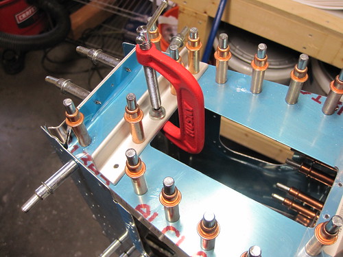
Next, the attention turned to the aft end. I was somewhat dreading putting the longerons in place, because I wasn't sure how accurate my bend had been, whether the notches would line up right with the horizontal stabilizer attachment bars, etc. But it turned out to fit perfectly. They snapped right into place with no problems at all. The F-1011 spacer that sits on top of one of the bulkheads needed some double-sided tape, and I didn't have enough clamps for the aft decking, so I made a quick trip to the hardware store. $18 and 20 minutes later I had this:
Very little manipulation was required to get the longerons to line up with the skin and deck edges the way they are meant to, and this was a relief. Unfortunately, it turns out that I'm an idiot and I didn't check that I had the requisite drill bit for drilling all of the skin/longeron holes (3/32"). Not an uncommon size, so I can see why I might have overlooked it... but that's the one drill bit of my set that had a broken tip and I tossed it last week. Great. So I need to go back to the hardware store, but I think I'll take a break for awhile first.
21 Feb 2010
Was out of town yesterday evening and half of today, but when I got back I got some more good progress done on the initial assembly of the tail cone parts. On my way back into town, I grabbed a pair of new 3/32" drill bits which allowed me to proceed with the longeron drilling.
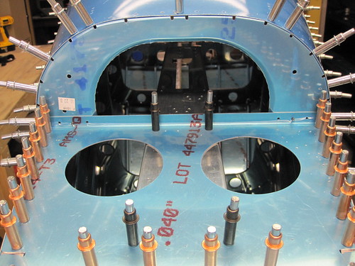
Doing the two rows of about 100 rivets took an hour and a half, with lots of clamp moving involved to ensure that the top of the skin lined up exactly with the top edge of the longerons. I encountered a problem with the middle two frames: the longeron cutout was a bit too low, and the frames weren't able to slide all the way out on the longeron as a result. The flanges closest to the longerons therefore were too far away and the holes didn't line up right.
I've decided I'm going to just match drill those holes next time I assemble the tail, and skip ahead to everything else for now. When I disassemble those frames, I'll file the offending bits off of the frames (marked in the black in the picture, above).
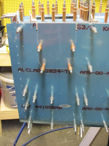
With the longerons done, work proceeded quickly getting the F-1009 mounted, the top stiffeners, and finally the two top skins. Here's the aft skin in place with the aft halves of the stiffeners match drilled:
And here is the forward top skin in place as well:
The matched holes feature of the Van's kits is a godsend; this would be such a huge pain if the holes didn't just magically line up. These skins are tight. It's like a giant drum.
I didn't finish match-drilling the stiffeners; I'm going to leave that for another night. This thing i huge, by the way, and really fills up my entire shop. Its overwhelming presence in the shop just acts as a huge motivator to keep working. I can't ignore it! :-D But for tonight I have to call it quits.
22 Feb 2010
Just a couple hours of work today, beginning with the completion of the match drilling of the top three stiffeners. After that, I drilled out the #30 holes connecting the aft deck to the longerons below:
Then I added the two custom-fabricated pieces of angle aluminum that I bought from iflyrv10.com. The support for the horizontal stabilizer attachment bars goes here:
The up elevator stop bracket goes here:
I spent some time looking ahead in the plans to find out what happened next with the access panels at the aft ends of the tail cone sides; turns out they don't get their top holes drilled until during the fitting of the empennage fairing, which doesn't get delivered until the fuselage kit! So I went ahead and drilled, deburred, and dimpled the four existing holes. These two parts go into the (currently very small) pile that is ready for primer!
I also went ahead to the empennage attach chapter of the plans and completed the fabrication steps there. The elevator pushrod was already complete and ready for primer; now the elevator trim servo mount is also complete. I cleco'd it into place under the aft deck because it is going to get a couple custom pieces added to it before it will be ready for primer.
Specifically, there will be a small tab that hangs down from the left side and holds a CPC panel mount recepticle for the servo wires.
With that, tail cone initial fabrication was complete! The next step in the plans is to disassemble the entire thing and begin the dreaded deburring process.
However, before I disassemble the structure, I want to add all the miscellaneous bits and pieces that will support the various custom hardware gizmos to be mounted in the tail. A not-necessarily complete list includes:
- ELT
- ELT antenna
- Oxygen tank
- Oxygen refill port
- Pitch autopilot servo
- Magnetometers
- Main battery and contactor
- External power receptacle and contactor
- VOR/LOC/GS antenna
- Static air system
- NACA inlets for overhead ventilation
- Conduit runs for cables
This is almost guaranteed to be a long time coming since I don't even have any of the above listed accessories yet other than the conduit and NACA inlets (though I do have the static system, ELT, ELT antenna, and the external power receptacle on order). I've got a bunch of gear to buy still, obviously. Add to this that I'm about to be deployed overseas for work for probably the bulk of March, and the RV-10 project is clearly about to go from rapid progress to a standstill for some time. But that's OK, in the meantime I've got an awesome-looking tail cone filling up my shop. Definitely still highly motivated!
| <-- January 2010 | March 2010 --> |