
| Workshop | Empennage | Wings | Fuselage | Contact |
Wingtip Construction
Current status: Under construction.
Time invested on this sub-assembly: 8 hours (8 by me)
Today I started work on the wingtips!
I decided awhile back that I wanted to use the hinge method of attachment for the wingtips rather than the stock screws and nutplates. For one thing, it looks better when it's done. Also, it makes removing the wingtips relatively quick and painless. My advisors have told me many times that if an inspection is difficult to do, then it won't happen nearly as often as it should. So I want to make getting into the internals of the plane as easy as possible. Plus, I've got a fair amount of gear planned to be mounted in the wingtips (APRS controller, pitot heat controller, NAV antenna, marker antenna, NAV lights, strobes, access to the landing lights, possibly landing lights, possibly a camera mount...) so if there's any issues with any of it, I'll need to be able to get the wingtips on and off, preferrably with minimal hassle.
There are lots of great walk-throughs for doing the hinge attachment on the web, but I couldn't find any specifically tailored to the RV-10 and none that also involved the Bob Archer NAV antenna installation. There are also some improvements to the method that I've found in some descriptions and not in others. I'm going to try to make this section as detailed as possible for any future builders that want to go down this path.
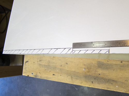
The first step was to define a rivet hole pattern in the wing skins for attachment of the inboard half of the hinge. For this, I used a rivet spacer like the one pictured here:
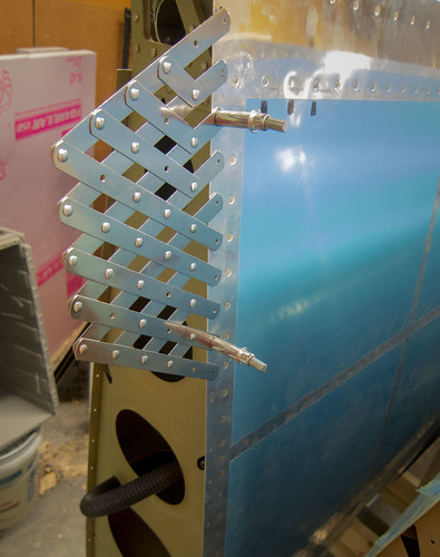
As you can see from the photograph, the rivet spacer makes it easy to make holes that line up with the existing rivets for the outboard rib. The stock holes for the wingtip (seen below the spacer in the photo) are only half as numerous as the rib rivets. I wanted holes for the hinge that lined up exactly with the rib holes next to them. In most cases, this just meant putting evenly-spaced holes between each pair of existing holes. However, around the rear spar, the J-stiffener, the main spar, etc. there were oddly-spaced rivets. I went ahead and duplicated the odd spacing using the rivet spacer tool in order to maintain a professional look. I also added two holes evenly-spaced between the rear spar and the gap fairing rivet lines.
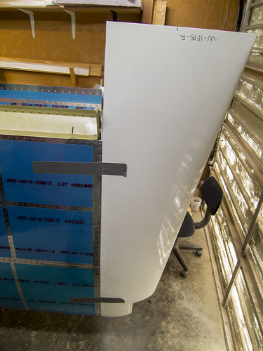
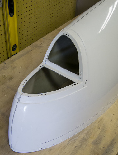
At the nose end, the hinge does not go all the way to the front in order to avoid strong curvature. It took some trial and error to determine how far the hinges should do, and here are the results: a 41.5" hinge on the bottom skin will go from the aft edge of the skin to the forward-most existing hole and not encounter any significant curvature. For the top skin, a 44" hinge will go from the aft edge of the skin to just forward of the second-forward-most of the stock holes. This means that when I was adding holes for the top skin, I did not add a hole between the two forward-most existing holes. Here's a photo of the nose area of the right wing for reference:
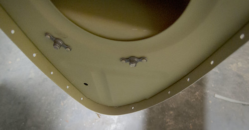
The lone forward-most hole on the top skin will not be used and will get filled in later.
Once I had measured and marked the hinges, I removed the pin and snipped them to length with metal snips. This left a sharp edge, which I buffed down with a scotchbrite wheel. Next, I had to choose which half of each hinge would be the inboard half. It is important that the inboard half of the hinge have an eye at the aft end, not a space. Once the hinge halves were marked, I took the inboard halves and clamped them in place, being sure to keep the aft edge flush with the aft edge of the wing skin and the inboard edge flush against the outboard wing rib. Here's a picture of the bottom hinge being match-drilled:
The technique here was nothing special; I just kept the hinge half clamped firmly in place and drilled through the skin into the hinge, adding a cleco for each hole as they were drilled. Clamps were discarded as I reached them. Drilling out both top and bottom inboard hinge halves went very quickly. The skins and hinges were deburred afterwards.
I can't rivet the hinges to the wing skin yet. There needs to be a spacer between the inboard hinge and the skin since the wingtip fiberglass is considerably thicker than the skin aluminum. Several writeups on how to make this spacer suggest using 0.040" aluminum shims, but there is a better method that requires nothing not already in-hand. The wingtip comes with an attachment flange that is thinner than the rest of the wingtip by the thickness of the skin. This flange is normally cut off and discarded when using hinges to attach the wingtips. However, the flange is exactly the right thickness to offset the inboard hinge half. So the basic plan of attack is to trim the wingtip with a 1/2" flange as if you were going to attach it conventionally, then trim the flange and use that as a spacer between the inboard hinge halves and the skin. Even better, the holes can be transferred into the spacer while the flange is still attached to the wingtip, and then the whole hinge used to make holes between the outboard hinge half and the wingtip without having to drill blind through a back-lit piece of fiberglass. All of that I will describe in better detail, with pictures, as I progress through this process.
8 Jul 2014
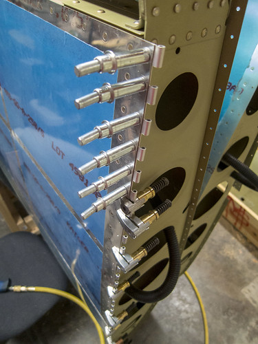
I've done a fair amount of work on the right wingtip over the last week. After my last post, I realized that I really wanted to use the MS20257-P4 hinges on my wingtips rather than the MS20257-P3 hinges that I cut and drilled previously. The reason for this is that the P4 hinges are slightly wider and will put the hinge eyelets fully inside the wingtip. This way, if there's any gap between the wingtip and wing skin, you'll just see the hinge flange beneath (which can be painted) rather than the eyelets. I think it'll be a cleaner install this way, and since I hadn't riveted anything yet, I went ahead and fabricated replacement hinges. Here's a picture of the new hinge about to be match-drilled to the hole pattern in the wing skin:
You can see how the hinge flange sticks out past the end of the wing skin by 1/8" now, whereas before it was flush with the skin.
Next, I started trimming the wingtip itself. The tip shipped with a 1.5" flange which had to be cut down to 0.5". I used a die grinder to make the cut. Here's a picture from three quarters of the way through the process:
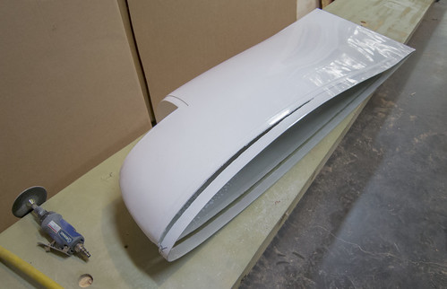
Once the flange was trimmed down, the wingtip still won't fit on the wing because the aft end runs into the aileron and aileron bearing hanger. I removed the aileron from the wing, but the bearing hangar rivets are still in the way, so I went ahead and made the final cuts to the wingtip's inboard edges.
As you can see here, the wingtip inboard edge gets cut an additional 1/2" in from the aft edges of the skin to the trailing edge, except for the first 3.25" on the bottom side, which only gets cut in 1/4". I made these cuts with a dremel. Once they were done, I could install the wingtip temporarily onto the wing without any major difficulty.
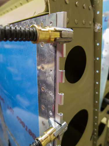
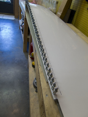
I ran into a few small obstructions where my 0.5" flange on the wingtip had to be shaved down a bit with a file because the outboard wing rib stuck out slightly here and there. After a few test-fits, I was able to tape down the wing and do the match-drilling of the wing skin's hole pattern into the fiberglass tip flange, clecoing as I went. Here's the result:
If you look closely in that picture, you can see that my 1/2" flanges extend slightly aft of the skins, despite the front of the wingtip being pressed firmly against the front wing skin. I trimmed that excess with a dremel shortly after this photo was taken.
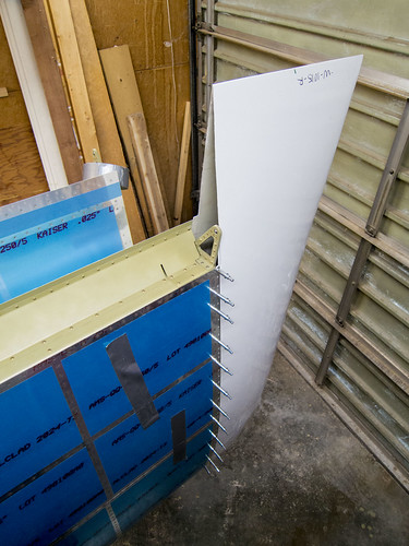
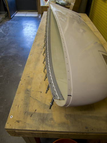
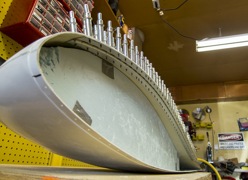
Now that the correct hole pattern is on both the wing-half of the hinges as well as the flange of the wingtip fiberglass, it was time to remove the wingtip and attach the flange to it (temporarily). This required putting the hinge pin back into the hinge, and I didn't want to cut the pin to length yet, so it sticks way out aft of the wingtip. Here's a photo of the full top hinge clecoed to the inside of the wingtip:
From here, I flipped the wingtip over and marked out the hole locations desired for the other half of the hinge on the outer surface of the wingtip. I also added clecos to every hole to ensure that the holes would be true. The new hole line is 1" outboard of the existing holes (which will put the holes roughly in the center of the outboard hinge halves if you're using the -P4 hinges).
From this point, it was an easy task to drill through the fiberglass and outboard hinge half at each marked location, filling the holes with clecos as I went.
With all the holes drilled, I removed the hinge from the wingtip, deburred the outboard half, removed the pin, and stored the hinge halves and pin for now. I have to repeat this process for the bottom hinge, then it'll be time to cut off the flange. But that'll come later.
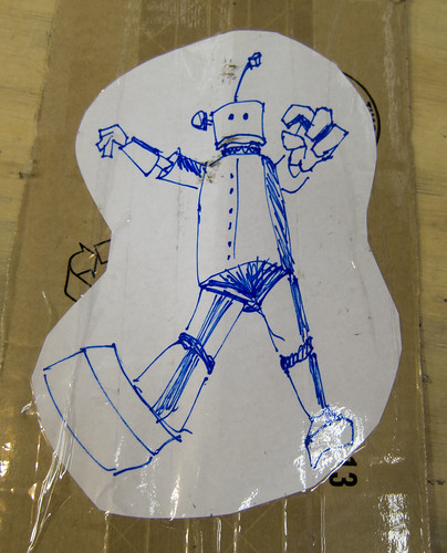
In the meantime, my NAV/POS wingtip lights showed up from Van's today! In the special notes section of the order form, I asked them to draw a robot on the box and the box showed up with this on the bottom:
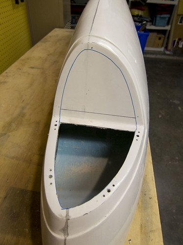
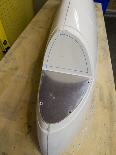
Nice work, Van's! Anyway, I was inspired to get some work done on the NAV/POS area. I knew I wanted to mount some reflective metal plates to both faces of the lighting recess, so I cut a couple pieces of 0.040" aluminum sheet to fit the odd shapes. Then I used a dremel to cut out all but a 0.5" flange of the outboard-facing facet.
As you can see, I put holes for four #6 nutplates around the edge to hold the metal plate to the wingtip. Lastly, I match-drilled the #21 holes for the screws through to the metal plate:
Now I can attach the lighting fixture to the metal plate without having to work inside the fiberglass wingtip. However, I'm going to wait on the final positioning of the light fixture until I know exactly where the plastic lens will be. So that's next.
13 Jul 2014
Since the last update, I have completed the hinge drilling for the right wingtip; both lengths of hinge are match-drilled and deburred and set aside for now. This clears me to cut the 0.5" flange (containing the inboard hinge holes) off the wingtip. But as this is a long, messy process, I elected to not do it yet and instead work more on the lighting recess. I had managed to mess up one of my lens cuts on the stock plastic, so I ordered replacement lenses from Cee Bailey's Aircraft Plastics which were much nicer. The quality of the plastic is better and they're pre-cut to the correct shape (the right one didn't need any trimming at all; we'll see how the left one fares). I'd recommend asking Van's to not include the lens part on their wing kit order and just order Bailey's; it's worth it in my opinion. Screwing up the stock plastic trimming is easy; ask me how I know. Oh, but don't ask Bailey's to draw anything on your box... even though they called me to ask whether I wanted a 1950's robot or a futuristic robot on the box, they didn't actually draw anything. Boo!
Anyway, once I had the right-side lens finalized, I match-drilled it into the top and bottom surface of the wing tip for the attachment screws. While I was doing nutplate hole patterns, I figured I might as well do them all. So I finished the lighting recess facet cutouts and added all seven of the nutplate hole patterns for attaching the aluminum base plates:
The AeroLEDs Pulsar NS90 LED navigation/strobe lights that I got for these lighting recesses require a chassis ground, so I decided that I'd run some grounding straps between the nutplates that attach the plates and (eventually) the hinge. That'll connect the metal of the base plates into the aircraft chassis and provide a good return for any accessories mounted there. Here's a photo of the nutplates installed around the lighting recess and the two grounding straps to connect everything to chassis ground:
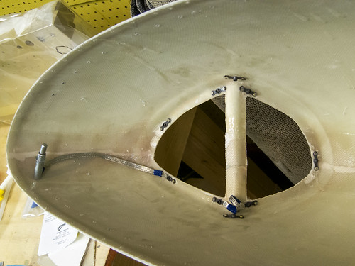
Once the plates are screwed into place, there should be good electrical contact between everything and I won't have to worry about it.
Time invested on this sub-assembly: 8 hours (8 by me)
Updates regarding wingtip construction
22 Jun 2014Today I started work on the wingtips!
I decided awhile back that I wanted to use the hinge method of attachment for the wingtips rather than the stock screws and nutplates. For one thing, it looks better when it's done. Also, it makes removing the wingtips relatively quick and painless. My advisors have told me many times that if an inspection is difficult to do, then it won't happen nearly as often as it should. So I want to make getting into the internals of the plane as easy as possible. Plus, I've got a fair amount of gear planned to be mounted in the wingtips (APRS controller, pitot heat controller, NAV antenna, marker antenna, NAV lights, strobes, access to the landing lights, possibly landing lights, possibly a camera mount...) so if there's any issues with any of it, I'll need to be able to get the wingtips on and off, preferrably with minimal hassle.
There are lots of great walk-throughs for doing the hinge attachment on the web, but I couldn't find any specifically tailored to the RV-10 and none that also involved the Bob Archer NAV antenna installation. There are also some improvements to the method that I've found in some descriptions and not in others. I'm going to try to make this section as detailed as possible for any future builders that want to go down this path.
The first step was to define a rivet hole pattern in the wing skins for attachment of the inboard half of the hinge. For this, I used a rivet spacer like the one pictured here:
As you can see from the photograph, the rivet spacer makes it easy to make holes that line up with the existing rivets for the outboard rib. The stock holes for the wingtip (seen below the spacer in the photo) are only half as numerous as the rib rivets. I wanted holes for the hinge that lined up exactly with the rib holes next to them. In most cases, this just meant putting evenly-spaced holes between each pair of existing holes. However, around the rear spar, the J-stiffener, the main spar, etc. there were oddly-spaced rivets. I went ahead and duplicated the odd spacing using the rivet spacer tool in order to maintain a professional look. I also added two holes evenly-spaced between the rear spar and the gap fairing rivet lines.
At the nose end, the hinge does not go all the way to the front in order to avoid strong curvature. It took some trial and error to determine how far the hinges should do, and here are the results: a 41.5" hinge on the bottom skin will go from the aft edge of the skin to the forward-most existing hole and not encounter any significant curvature. For the top skin, a 44" hinge will go from the aft edge of the skin to just forward of the second-forward-most of the stock holes. This means that when I was adding holes for the top skin, I did not add a hole between the two forward-most existing holes. Here's a photo of the nose area of the right wing for reference:
The lone forward-most hole on the top skin will not be used and will get filled in later.
Once I had measured and marked the hinges, I removed the pin and snipped them to length with metal snips. This left a sharp edge, which I buffed down with a scotchbrite wheel. Next, I had to choose which half of each hinge would be the inboard half. It is important that the inboard half of the hinge have an eye at the aft end, not a space. Once the hinge halves were marked, I took the inboard halves and clamped them in place, being sure to keep the aft edge flush with the aft edge of the wing skin and the inboard edge flush against the outboard wing rib. Here's a picture of the bottom hinge being match-drilled:
The technique here was nothing special; I just kept the hinge half clamped firmly in place and drilled through the skin into the hinge, adding a cleco for each hole as they were drilled. Clamps were discarded as I reached them. Drilling out both top and bottom inboard hinge halves went very quickly. The skins and hinges were deburred afterwards.
I can't rivet the hinges to the wing skin yet. There needs to be a spacer between the inboard hinge and the skin since the wingtip fiberglass is considerably thicker than the skin aluminum. Several writeups on how to make this spacer suggest using 0.040" aluminum shims, but there is a better method that requires nothing not already in-hand. The wingtip comes with an attachment flange that is thinner than the rest of the wingtip by the thickness of the skin. This flange is normally cut off and discarded when using hinges to attach the wingtips. However, the flange is exactly the right thickness to offset the inboard hinge half. So the basic plan of attack is to trim the wingtip with a 1/2" flange as if you were going to attach it conventionally, then trim the flange and use that as a spacer between the inboard hinge halves and the skin. Even better, the holes can be transferred into the spacer while the flange is still attached to the wingtip, and then the whole hinge used to make holes between the outboard hinge half and the wingtip without having to drill blind through a back-lit piece of fiberglass. All of that I will describe in better detail, with pictures, as I progress through this process.
8 Jul 2014
I've done a fair amount of work on the right wingtip over the last week. After my last post, I realized that I really wanted to use the MS20257-P4 hinges on my wingtips rather than the MS20257-P3 hinges that I cut and drilled previously. The reason for this is that the P4 hinges are slightly wider and will put the hinge eyelets fully inside the wingtip. This way, if there's any gap between the wingtip and wing skin, you'll just see the hinge flange beneath (which can be painted) rather than the eyelets. I think it'll be a cleaner install this way, and since I hadn't riveted anything yet, I went ahead and fabricated replacement hinges. Here's a picture of the new hinge about to be match-drilled to the hole pattern in the wing skin:
You can see how the hinge flange sticks out past the end of the wing skin by 1/8" now, whereas before it was flush with the skin.
Next, I started trimming the wingtip itself. The tip shipped with a 1.5" flange which had to be cut down to 0.5". I used a die grinder to make the cut. Here's a picture from three quarters of the way through the process:
Once the flange was trimmed down, the wingtip still won't fit on the wing because the aft end runs into the aileron and aileron bearing hanger. I removed the aileron from the wing, but the bearing hangar rivets are still in the way, so I went ahead and made the final cuts to the wingtip's inboard edges.
As you can see here, the wingtip inboard edge gets cut an additional 1/2" in from the aft edges of the skin to the trailing edge, except for the first 3.25" on the bottom side, which only gets cut in 1/4". I made these cuts with a dremel. Once they were done, I could install the wingtip temporarily onto the wing without any major difficulty.
I ran into a few small obstructions where my 0.5" flange on the wingtip had to be shaved down a bit with a file because the outboard wing rib stuck out slightly here and there. After a few test-fits, I was able to tape down the wing and do the match-drilling of the wing skin's hole pattern into the fiberglass tip flange, clecoing as I went. Here's the result:
If you look closely in that picture, you can see that my 1/2" flanges extend slightly aft of the skins, despite the front of the wingtip being pressed firmly against the front wing skin. I trimmed that excess with a dremel shortly after this photo was taken.
Now that the correct hole pattern is on both the wing-half of the hinges as well as the flange of the wingtip fiberglass, it was time to remove the wingtip and attach the flange to it (temporarily). This required putting the hinge pin back into the hinge, and I didn't want to cut the pin to length yet, so it sticks way out aft of the wingtip. Here's a photo of the full top hinge clecoed to the inside of the wingtip:
From here, I flipped the wingtip over and marked out the hole locations desired for the other half of the hinge on the outer surface of the wingtip. I also added clecos to every hole to ensure that the holes would be true. The new hole line is 1" outboard of the existing holes (which will put the holes roughly in the center of the outboard hinge halves if you're using the -P4 hinges).
From this point, it was an easy task to drill through the fiberglass and outboard hinge half at each marked location, filling the holes with clecos as I went.
With all the holes drilled, I removed the hinge from the wingtip, deburred the outboard half, removed the pin, and stored the hinge halves and pin for now. I have to repeat this process for the bottom hinge, then it'll be time to cut off the flange. But that'll come later.
In the meantime, my NAV/POS wingtip lights showed up from Van's today! In the special notes section of the order form, I asked them to draw a robot on the box and the box showed up with this on the bottom:
Nice work, Van's! Anyway, I was inspired to get some work done on the NAV/POS area. I knew I wanted to mount some reflective metal plates to both faces of the lighting recess, so I cut a couple pieces of 0.040" aluminum sheet to fit the odd shapes. Then I used a dremel to cut out all but a 0.5" flange of the outboard-facing facet.
As you can see, I put holes for four #6 nutplates around the edge to hold the metal plate to the wingtip. Lastly, I match-drilled the #21 holes for the screws through to the metal plate:
Now I can attach the lighting fixture to the metal plate without having to work inside the fiberglass wingtip. However, I'm going to wait on the final positioning of the light fixture until I know exactly where the plastic lens will be. So that's next.
13 Jul 2014
Since the last update, I have completed the hinge drilling for the right wingtip; both lengths of hinge are match-drilled and deburred and set aside for now. This clears me to cut the 0.5" flange (containing the inboard hinge holes) off the wingtip. But as this is a long, messy process, I elected to not do it yet and instead work more on the lighting recess. I had managed to mess up one of my lens cuts on the stock plastic, so I ordered replacement lenses from Cee Bailey's Aircraft Plastics which were much nicer. The quality of the plastic is better and they're pre-cut to the correct shape (the right one didn't need any trimming at all; we'll see how the left one fares). I'd recommend asking Van's to not include the lens part on their wing kit order and just order Bailey's; it's worth it in my opinion. Screwing up the stock plastic trimming is easy; ask me how I know. Oh, but don't ask Bailey's to draw anything on your box... even though they called me to ask whether I wanted a 1950's robot or a futuristic robot on the box, they didn't actually draw anything. Boo!
Anyway, once I had the right-side lens finalized, I match-drilled it into the top and bottom surface of the wing tip for the attachment screws. While I was doing nutplate hole patterns, I figured I might as well do them all. So I finished the lighting recess facet cutouts and added all seven of the nutplate hole patterns for attaching the aluminum base plates:
The AeroLEDs Pulsar NS90 LED navigation/strobe lights that I got for these lighting recesses require a chassis ground, so I decided that I'd run some grounding straps between the nutplates that attach the plates and (eventually) the hinge. That'll connect the metal of the base plates into the aircraft chassis and provide a good return for any accessories mounted there. Here's a photo of the nutplates installed around the lighting recess and the two grounding straps to connect everything to chassis ground:
Once the plates are screwed into place, there should be good electrical contact between everything and I won't have to worry about it.