| Workshop | Empennage | Wings | Fuselage | Contact |
Wing Body Construction
Current status: Under construction.
Time invested on this sub-assembly: 166 hours (135 by me)
I started working on the first chapter in the wing plans, which covers the main wing spars. Unfortunately, it accomplishes almost nothing before needing a small amount of priming. I got the extensions and their splice brackets matched drilled and deburred, which made them ready for priming. Then I skipped ahead a bit and match drilled the two tie down brackets. My wee bandsaw wasn't hearty enough to trim the brackets to length, so I went to Bob's shop to use the megasaw. Cut through it like butter.
With these few parts ready for priming, there was nothing left to do in that section without first priming these bits, and I didn't want to deal with the overhead of priming for just 12 small parts. So next I'll continue on with some other section and get additional parts ready for priming.
23 Jan 2011
Right main spar marathon.
Priming done, it was time for some riveting. I decided to go back to the first chapter of the wing kit, the main spar, and continue again where I had paused pending priming. This meant riveting the spar extensions and doubler plates in place.
These all required the gun and bucking bar, but were easy enough to do by myself. I did the extensions for both spars. I decided to continue onwards with the main spar chapter, doing the right spar first since it was the one still sitting on my workbench. The next step was to match drill the holes in the wing box J-stiffeners.
This was pretty straightforward and took less time than I thought despite the multitude of holes.
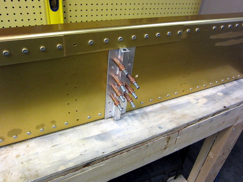
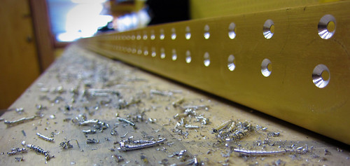
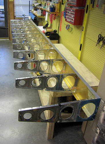
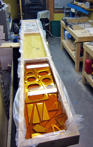
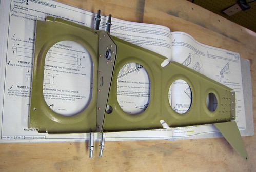
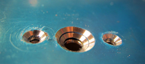
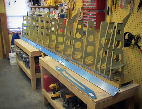
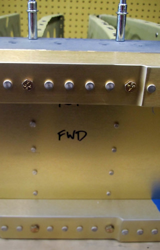
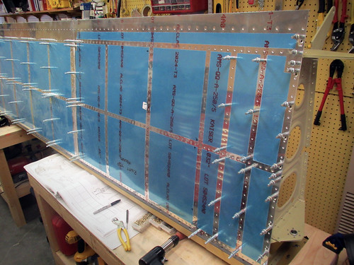
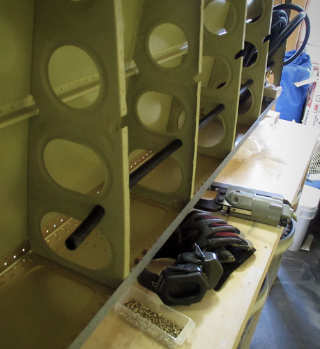
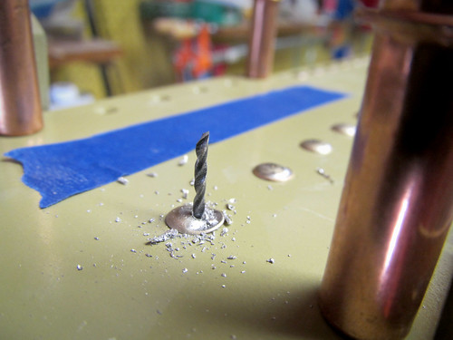
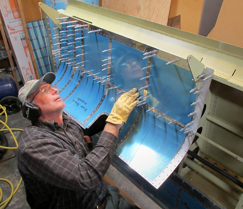
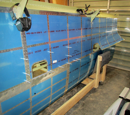
Speaking of holes, the next few steps were all about countersinking. Every single hole in the flange of the spar gets countersunk (except, I think, the "extra hole" in the bottom of the extension on each side). That's about 52 linear feet of flange with a couple holes per inch. This took forever, and I only did one of the spars. The outcome, however, was awesome.
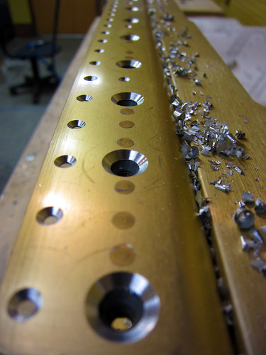
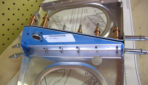
In the above shot you can see that I've already put in the fuel tank attach nutplates as well, so the flanges are basically complete here. The only task remaining on them is to spot-prime those enormous countersinks. I haven't decided how I'm going to do that yet, and it isn't critical path until the time comes to attach the leading edge to the spar (which is a long way off), so I'm tabling that step for now.
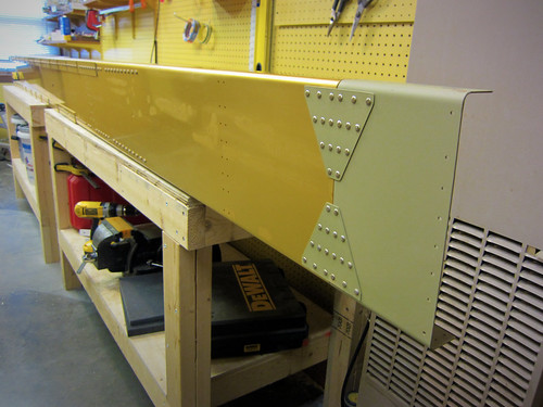
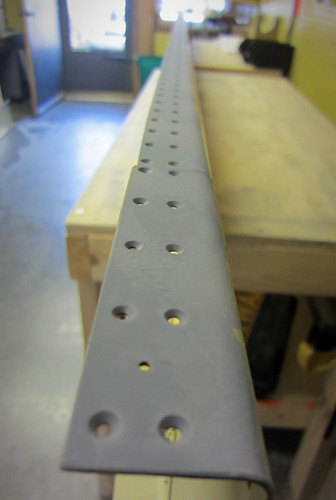
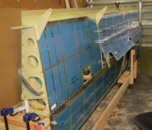
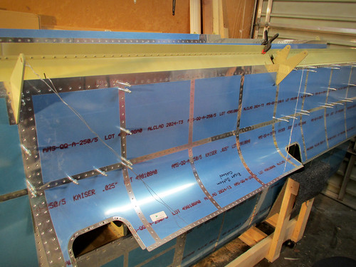
Here's another view where you can see the plethora of nutplates:
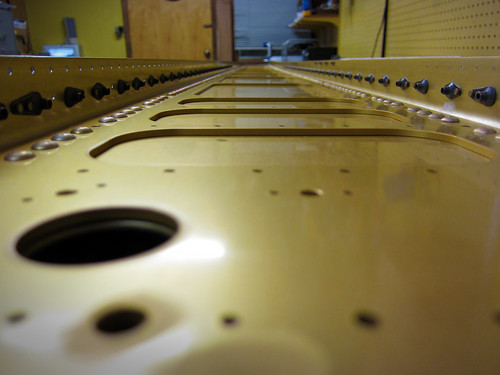
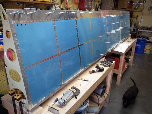
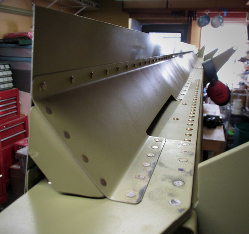
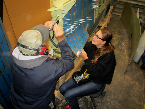
I spent most of the day between the flange nutplates and the countersinking. When that was all done, there was a short encore for the wing root area, where there just five more nutplates to do and three random rivets.
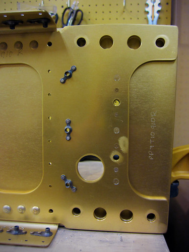
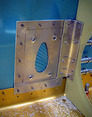
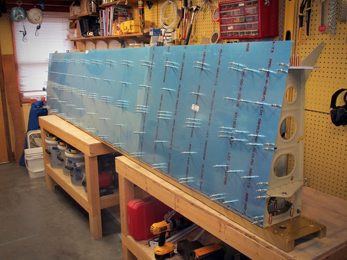
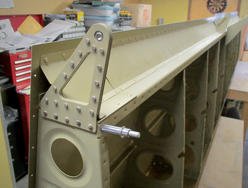
For the life of me, I couldn't find where in the plans it says to actually attach the "wing attach nutplates" on the right side of this image. The diagram shows them going on here, but the text does not. As you can see, I went ahead and put them on. I hope that doesn't bite me in the ass when it comes time for wing attach, later...
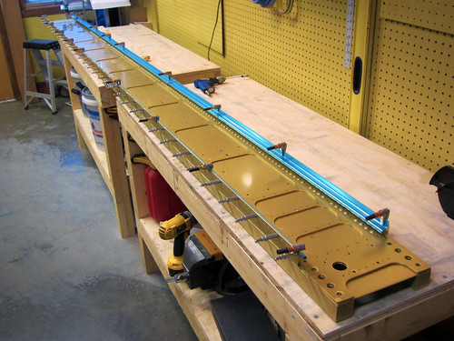
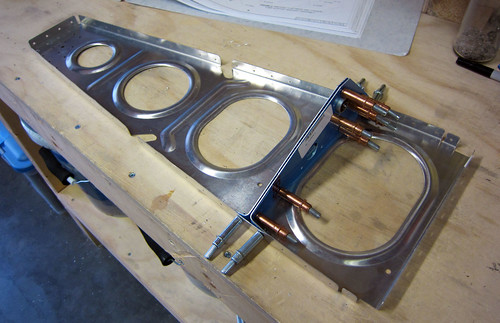
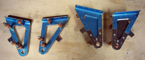
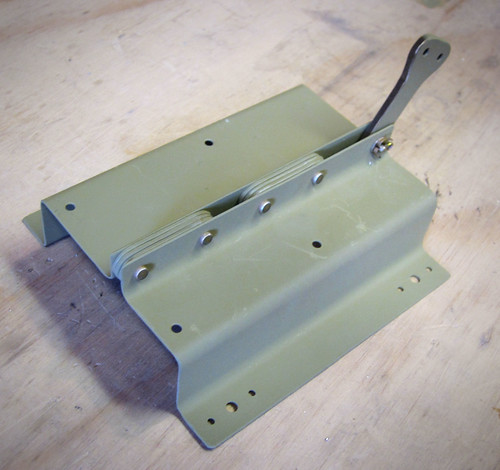
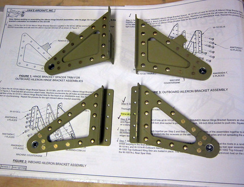
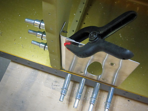
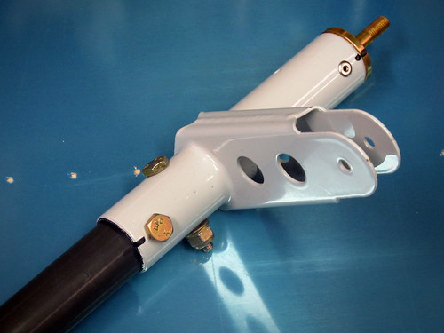
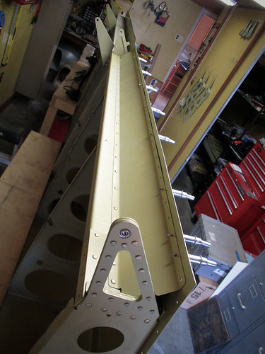
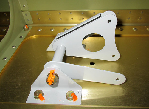
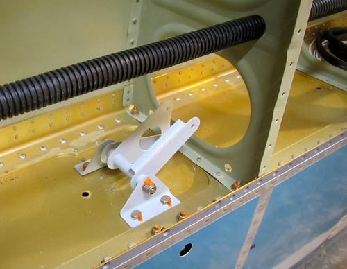
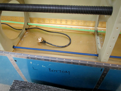
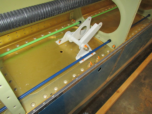
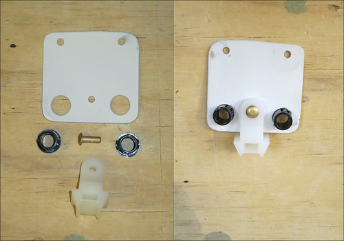
The last little bit of work involves the tie down block and aileron bellcrank bracket. These were quick to install. Here's the brackets:
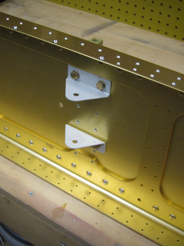
And here's the tie-down:
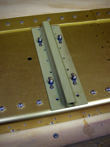
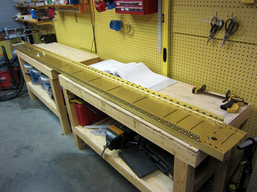
As you can see, I neglected to actually do the rivets. I got so excited about being done with one of the spars that I put away all my tools before realizing I hadn't finished this step. Oh well, I'll finish that up next time. It's just 10 rivets anyway. Here's the final shot of the essentially-done spar:
Tim Olson was right when he said that this section was a bit frustrating in that you do tons of work and in the end it doesn't look much different. The bits that are obviously different (the extensions and the tie down/bellcrank bracket) were by far the quickest to do. Oh well. I'm still pumped to have this behind me.
30 Jan 2011
Still waiting on help with the riveting of the right leading edge, so I set it aside and hauled out the left main spar. Over the last three days I've managed to get it almost complete.
There's nothing significantly different about this one than the right-side one that I did last week, so I didn't take much in the way of pictures. All that is left at this point is to spot-prime the countersunk holes.
5 Jun 2011
With the leading edge finally off the workbench, I had room to get the second wing spar up on the tables and prime its flanges. This was the last step left in the main spar chapter of the plans, so with those done I moved them into the garage for storage. They won't be needed again until I have the cradles built and am ready to attach the leading edges and fuel tanks to the spar.
18 Jul 2011
For a change of pace, I did a bit of get-ahead work on the aileron actuation chapter of the plans. There are three main assemblies that need attention prior to a priming pass—the torque tubes, the main pushrods, and the bellcrank-to-aileron pushrods.
The main pushrods just require a cut-to-length and match drilling the end pieces on. I had Bob do the cuts for me on Pat's huge bandsaw. The match-drilling and deburring took no time at all.
The smaller pushrods require a length cut, which Bob took care of for me, and then some match-drilling that needs a V-block (which I don't currently have), so they're on hold.
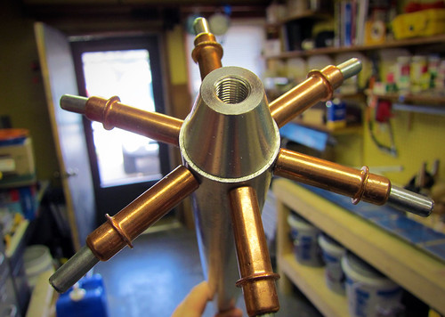
Each of the two torque tubes is composed of two end weldments, two threaded inserts, and a collar connecting them. Bob cut the collar stock for me, and I match-drilled and riveted the threaded ends into the weldments.
For some reason, the threaded ends get riveted in prior to priming as per the plans, and only the forward ends and the collar get primed (??). Not sure if that's an omission in the plans or if there is a good reason.
25 Jul 2011
I did a couple of minor things today. First I deburred and dimpled the last of the aileron skins so they are all done now and ready for final assembly.
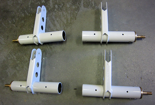
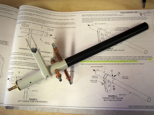
Next, I picked up my cut torque tube collars and replacement fuel sender access panel cover (I had mis-drilled one of the ones I made before) from Bob. When I got home from work, I set to work continuing the aileron actuation chapter by putting together the forward torque tube assemblies. The first step here was to match drill the weldments into the torque tube collars.
This went without a hitch. The next step was to drill #12 the matched holes out so that a AN3 bolt will fit through. On one of the torque tubes, this went flawlessly:
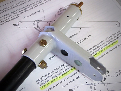
Unfortunately, on the other one, I managed to get the drill out of alignment somehow and made a huge oval out of one of the holes in both the collar and the weldment. So that piece is ruined. At a minimum, I'll need to order a new weldment ($60) and a new piece of the pipe ($20). If I can't get the pop rivets out cleanly, I'll also need a new end cap ($8). With shipping, I'm looking at about $100 for a botched drill job. Ouch. Probably the most expensive mistake in the plane thus far.
1 Aug 2011
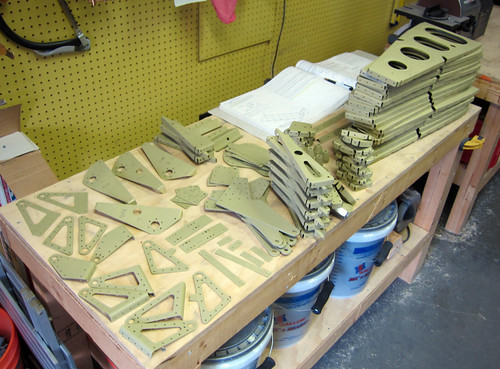
I started the wing ribs chapter this past weekend because I had convinced myself that they would need to be completed before the fuel tanks. The first bit was fluting and flattening all of the ribs. Nothing photo-worthy there... Next was getting the torque tube bearing brackets match-drilled for the inboard ribs.
I ended up needing a larger bandsaw than I have to make the cuts for the angle pieces that support the bracket (the required width is about 1cm too big for the throat of my bandsaw), so these bracket assemblies aren't quite done. But they're very close. I also got the flap hangers done on each of the three ribs that they attach to, but didn't take any pictures of that. The exception to this was the reaming of the flap attach holes, which I'm also saving for a trip to Pat's shop because I don't have any reamer bits.
From the aft spar chapter, I went ahead and did the aileron hinge brackets as well. These were quick, but again I needed a beefier bandsaw to cut off the tabs on the outboard brackets, so they're not quite done either.
So there's not much left on the wing ribs; just a few fabrication steps that need to happen elsewhere, and a bit of follow-up once those pieces are cut. Then there's just two major steps: match-drill all the ribs to the spars, then deburr/dimple everything. I may also go ahead and figure out how much I want to drill out the wiring and plumbing holes and do so before the priming (despite the plans' doing this after priming).
8 Aug 2011
I got the angle pieces cut for the forward torque tube brackets, got them match-drilled into the ribs and brackets, and then enlarged the conduit holes using a unibit.
I noticed that the holes in my ribs are all lined up, whereas Tim Olson's seem to be offset after the first one. I like this arrangement better and hope that the straight-through 3/4" plastic conduit won't interfere with the aileron bellcrank. Eyeballing it, it seems like it should be fine.
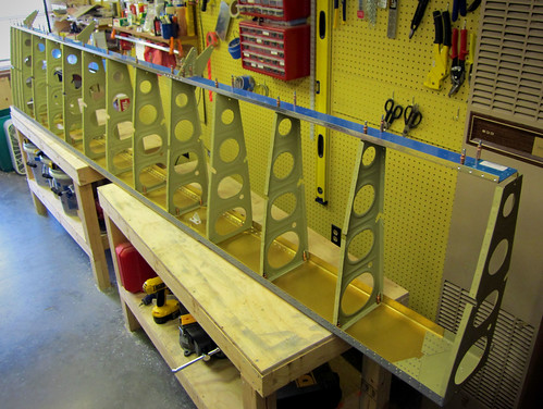
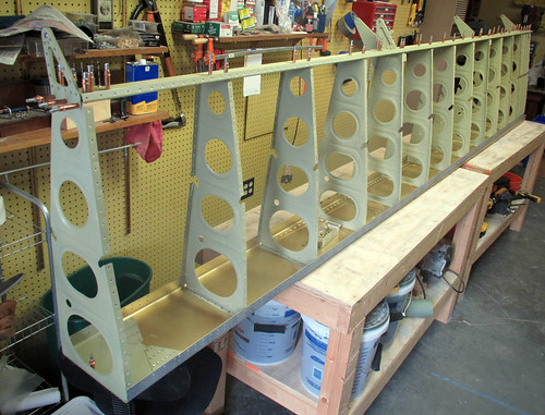
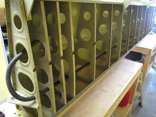
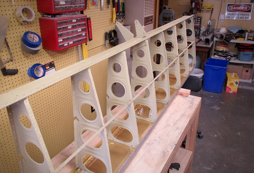
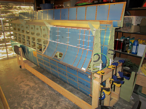
I went ahead and continued with the wing ribs chapter, attaching all of the ribs to the spars in order to match-drill the holes they share. The beginnings of a wing shape in the shop was exciting.
28 Aug 2011
Back in town after a work trip. Finished off the fluting of the wing ribs, the match drilling of the wing ribs to the spars, and the deburring of the freshly-drilled holes in the spar.
I took the flap hangers up to the airport where Jeff let me use his 3/8" reamer bit to finish off the hinge holes, rendering those parts ready for surface chemistry.
11 Sep 2011
It has been an epic weekend of plane progress! On Saturday, Jeremy helped me finish off all deburring and dimpling tasks required for the next round of surface chemistry and priming. This included all of the wing ribs and fuel tank ribs as well as numerous smaller pieces.
With that, it was time to do another iteration of the Alumiprep/Alodine/Akzo chemistry fiesta. The trouble was that my dunk tank only accepts long/narrow pieces so I had to construct something that would fit the wide wing ribs in it. After a moment of considering building a new tank, I had the brainwave of just removing the center rail from my existing tank and installing some beams that go across the tank the short way, dividing it up into three 1.5 x 4 foot tanks.
Perfect. The only problem with this arrangement is that I can only fit two wing ribs in a given bay at a time, which means at least 15 cycles through the process to get all 30 wing ribs done plus additional cycles for the tank ribs, though these fit four at a time (and you can get a single tank rib in with the two wing ribs, too). Other than the fact that I had a ton of parts to run through the chemistry processes, everything went smoothly. I probably should have started earlier than 7pm on Saturday... because it took me a little over six hours to finish everything. Went to bed at 2am. Wow.
After sleeping in a few hours late, I set about priming all of the non-fueltank parts this morning. Immediately ran into a snag: the primer from the last pass had not been cleaned out of the spray gun effectively and had solidified. It was unrecoverable. So I ran to the hardware store to get a replacement spray gun, only to find that the generic one they had at half the cost of my old one was significantly better! Win. I also found that I'm just about out of my first cans of Akzo. Hard to believe that a gallon of primer has already gone into this thing. I suspect I'm using it too thick or wasting a lot. Anyway, the priming went reasonably quick. Misjudged the amount I'd need twice, so had to make three batches. Luckily, the third batch was almost exactly used up on the last parts.
For the first time, I did the priming out in the driveway because the weather was nice. This meant I didn't have to waste time turning the shop into a paint booth, fog the room with fumes, or wear a silly outfit to get the job done. Got some weird looks from joggers running by as I went to work wearing my respirator and goggles... but whatever. The sun dried the primer in just moments so the whole thing went very fast.
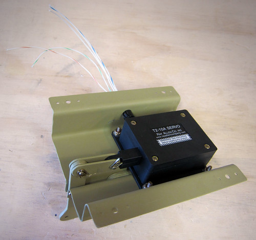
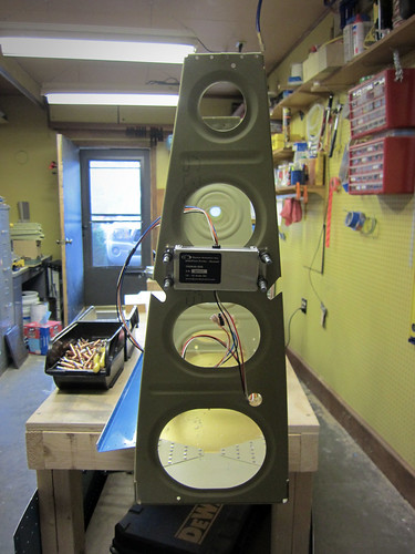
I immediately started riveting together those subsections that were now ready. First up was the aileron trim module. The housing went together quickly:
And the servo mounted into the housing:
Next up were the wing ribs that had flap hangers at the aft end. This includes the inboard ribs, which also have the torque tube support bracket and bearing:
Lastly I did the aileron hanger brackets. I already knew that I had accidentally countersunk two extra holes on the inboard units; this wasn't a problem because I can just use 426 rivets in them and they'll work fine. What I didn't realize until I sat down to rivet them was that I had forgotten to countersink the outboard brackets at all. So this was done and then the parts were riveted together.
With these subassemblies done, I went through the wing plans checking for anything else that could be done out of order as get-ahead work and came up empty. So now it's time to clear the work benches and get ready for the top skin and aft spar sections! Soon, I'll have to build a rolling cart for the wings.
14 Sep 2011
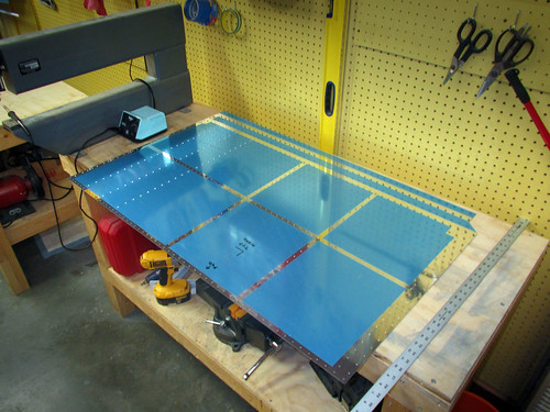
With the ribs primed and their accessories riveted in place, I took some time to assemble the rest of the main wing box. I clecoed the ribs to the main spar and then attached the aft spar on top of the ribs.
The plans call for you to rivet the ribs onto the main spar before proceeding to the aft spar, but I'm not sure why. In the interest of saving some space for awhile, I'm going to go quite a ways ahead in the plans with just clecos so that I can get all of the match-drilling, deburing, and dimpling out of the way. So, after the aft spar, I went ahead and put the top skins on, then the gap fairings, then the aft skins.
The plans make a big fuss about not match-drilling this row or that because of some later part that needs to be added, but by pre-assembling all of these parts, pretty much all of the holes are now ready for drilling. Over the coming days, I'll finish all of the match drilling, deburing, and dimpling on the left wing box and then can fully disassemble it without having to store it in its bulky form. There's no real accessory work that needs to be dealth with until I've actually riveted the main spar, ribs, aft spar, and top skin sections together. But before I get there, I'll need to have done the final priming pass on the long parts. And before I do that, I'm going to get all this preparatory work done on both wing boxes as well as the flaps.
19 Sep 2011
Did a bunch of drilling on the left wing box over the last couple days. All of the holes in the top skins are now drilled (with the exception of the wing tip attach holes). I also drilled out the gap fairing to rear spar holes, which rendered both left gap fairing pieces ready for deburring. These were removed and set aside for later. All of the holes in the top skin that go through the wing walk stiffeners were countersunk as well as all of the screw holes on the inboard edge except the aft-most one, which was dimpled for #8.
So at this point all the drilling is done for the gap fairings, the top skins, the wing walk doublers, and the rear spar components. Just the bottom skin drilling remains and should go quickly as there is very little countersinking on that side. Then it'll be time to disassemble and debur everything, then do it all again on the right side.
27 Sep 2011
Finished up all of the match drilling on the left wing! Doesn't look any different, but all of the skin parts, the rear spar assembly, and the skin holes on the ribs are all ready for deburring and dimpling. I also ripped out all six of the wing access covers.
These were pretty quick, just final drilling each hole, deburring the holes and edges, then dimpling. They're all set for surface chemistry and priming on the inner surface. Time to disassemble the left wing!
8 Oct 2011
Today is the second anniversary of the arrival of my empennage kit! Two years in and I'm about half-way done with the wings. Like I've said before, this is not a speed-build.
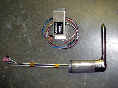
Today was all about the pitot tube. My Dynon heated pitot/AoA probe arrived in the mail last week, along with the matching Gretz mount kit (and my Bob Archer NAV antenna and some more Akzo).
I had been spending a lot of time recently deburring the outer face of the skins of the left wing, and yesterday I finally got to the point where the outboard bottom skin was ready to come off. With the skin off, I had access to the areas I needed to begin fabricating the pitot doubler and its accessories.
The doubler that comes with the Gretz mount has a joggled end piece that goes on the inside of the aft row of rivet holes in the main spar flange. The only questions is where along the spar to place the pitot tube. Gretz recommends putting it adjacent to a bay with an access panel and outboard of the aileron actuation hardware. However, they also caution against putting it near the tie-down lest the probe interfere with the rope. I decided to go with the same position Tim Olson did, which was the second bay inboard from the wing tip, up against the outboard-side rib (see above).
With the location selected, I centered the doubler on four holes of the spar flange and match-drilled them. If I had put the doubler up against the rib, only three of the holes would have lined up with the doubler. I decided that having a fourth hole and a longer angle bracket connecting to the rib was better than three holes and a shorter angle bracket. Fabricating the angle bracket was easy, I just bent a piece of 0.032" alclad plate and match drilled it to the rib with four holes.
I did not drill out any more of the holes in the doubler, including the ones shared with the angle bracket, because I wanted to drill these from the inside so I could tell easily that the holes would be well-aligned on the parts. However, to do this, I'd need to have the top skin off the wing and have the bottom skin back on the wing. I'm glad I did this before riveting the top skin; I'd recommend the same to any other builder. Anyway, I went ahead and finished all the outer-surface deburring on the outboard top skin and removed it, then cleco'd the outboard bottom skin back in place. After sliding the pitot doubler inbetween the angle bracket and the skin, and clecoing the forward row of holes, I was able to centerpunch and drill a series of 10 additional rivet holes connecting the doubler, angle bracket, and bottom skin.
I also match drilled the four screw holes for attachment of the pitot mount and marked the teardrop area of the skin for removal. I put a few big holes in the teardrop using a unibit, then took the skin back off (again) and opened up the rest of the hole with a nibbler and some files. After a few test fits, the teardrop hole was perfect and I put the skin back on (again) for a full fit test fo the pitot system.
Nothing too exciting to report about the outside, other than it fits well and looks good.
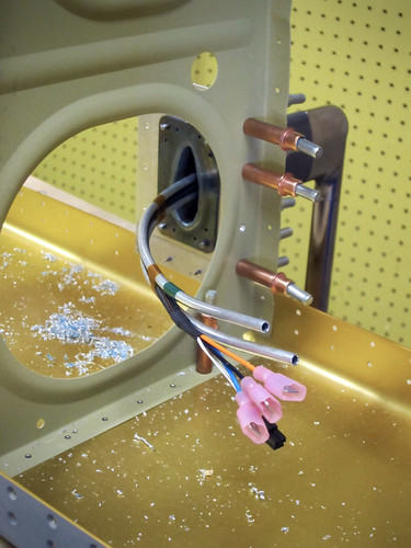
The inside view shows the two pressure tubes coming up through the mount as well as the heater control wires. I'm going to mount the heater control box on the outboard face of the outboard wing rib so that it is directly accessible from the wingtip. The wires are sufficiently long already, and can be secured to the outer surface of the conduit if need be. I'll bend the pressure tubes outboard as well, so that the aluminum tube to plastic tube adapters can be easily reached from the wingtip. Forming the tubes so that they can be inserted through the straight mount pipe but still curve through the lightening hole in the rib is the next problem to be solved.
10 Oct 2011
Did a bit more work on the pitot tube assembly this weekend; got the tubing and wire run coming up out of the pitot tube bent over and through the adjacent lightening hole.
Also, I finished deburring the outer surface holes of all left wing skins. I started disassembling the left wing and prepping the smaller parts as I separated them. The aft spar doubler plates are ready for chemistry, as are the wing walk doublers and all of the pieces associated with the pitot tube. I did a bunch of hole deburring, but there is still quite a bit left (lots of holes in the wings!!). As I'm taking individual ribs off of the main spar, I'm deburring the flanges and dimpling where appropriate, and expanding the forward tooling hole for use by the pitot plumbing line. I'll need to figure out where I'm going to mount my APRS equipment (probably the left wingtip) and run some wire holes for that antenna as well (the APRS antenna will be located one bay inboard of the pitot tube). Here's a list for my own bookkeeping of tasks remaining on the left wing before it will essentially be ready for the next chemistry pass, at which point I'll shelve it and start on the right wing.
6 Nov 2011
It has been awhile since I updated the site, but this is not due to a lack of work on the plane. Progress has been made; most of it just hasn't been very photogenic. Here's a quick re-cap.
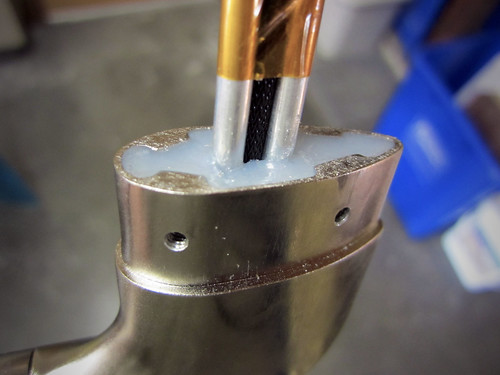
I got the mount holes in the pitot assembly drilled and tapped so that it mates up with the Gretz mast. I also countersunk the holes in the mast, but didn't take a picture of that.
I also decided where I was going to mount the pitot heater control box—inside the wingtip on the outboard face of the outboard wing rib. This makes it easily accessible should maintenance or replacement be needed. I put holes for four nutplates into the rib so the box can be screwed into place.
I still need to get the two aluminum tubes that come out of the pitot assembly flared. Jeff has offered to give me a clinic on how to do tube flaring since I've never done it before, I just haven't been able to find the time to get the pitot up to his hangar. Coming soon.
With the pitot work mostly done, I've been concentrating on getting the left wing disassembled and all the parts ready for the next primer pass. Here's the current version of the checklist that I posted last month:
This was enough items checked off the list that I was able to stow the main spar, rear spar, and ribs which frees up my workbenches finally.
Still a lot of work ahead, mostly in the form of deburring and dimpling the skins. I'm not sure how to do the lap joint correctly yet; I'm thinking I'll skip doing it on the bottom side entirely, since it is an aesthetic thing anyway (right?). Deburring huge wing skins is not fun, so I'm splitting the work up into little managable junks. I expect the progress over the next few weeks to be somewhat underwhelming and unphotogenic.
30 Nov 2011
Just an end-of-month update. Progress continues, slowly, on deburring and dimpling various left wing pieces. Nothing photo-worthy. Between getting married, moving Nina in, and spending a week in Florida, November's progress wasn't stellar.
29 Dec 2011
I got all of the deburring done on the left wing skins. It went faster than I expected it to when I finally convinced myself to sit down and do it.
I also got the stripes taken off of the outer surface rivet lines. Lastly, on the inner surface, I got the vinyl removed and the scuffing all done. So at this point, the wing skins are ready to have the taper applied to the lap joints and then will be ready for dimpling and priming.
21 Jan 2012
Spent the first two weeks of this month on a business trip, but today I got back to work on the plane. I decided that the left wing lap joint work would be best saved for when I could do all four pieces at once. This precluded me from doing any of the dimpling on the left skins as well, so I shelved all of the left wing parts and started on the right wing!
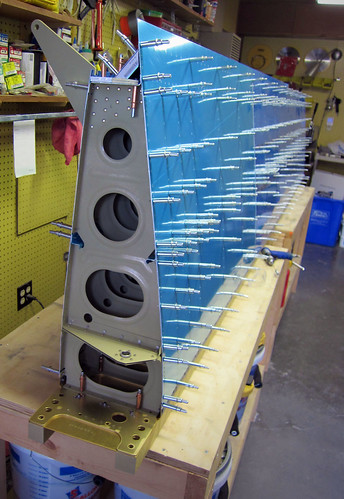
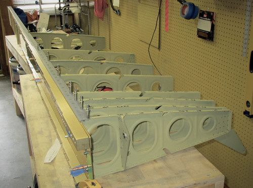
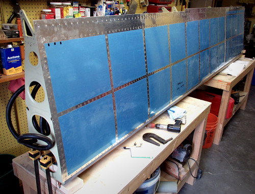
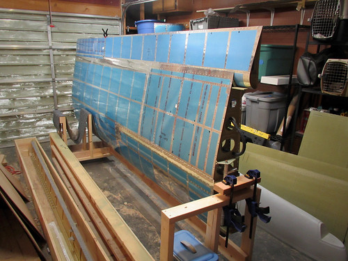
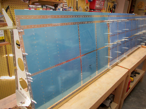
I pulled the main spar out of the garage and got it set up on the workbenches. Attaching the 15 ribs went quickly, then I set to work on the rear spar parts. These also took little time, then everything was cleco'd together and the top skins were hung:
The next step is to match-drill all of these holes, which was a formidable-enough barrier that it made for a good stopping point.
22 Jan 2012
Followed up yesterday's work by hanging the bottom skins on the ribs and adding the gap fairings and stiffener. This made for a more-or-less fully-assembled right wing body, so I started in on the match drilling. I did all of the top skin holes including all of the countersinking above the wing walk doublers. Also match drilled all of the gap fairing holes. I called it a day before working on the bottom skins as all of the drilling and cleco work had put some blisters into my hands. Nothing worth photographing...
2 Feb 2012
Got a few more deburring tasks done on the main wing body. Most importantly, finished off the aft row of holes on both flanges of the right main spar so that it could go back into the garage for storage until the wing is ready for assembly. Next I knocked out the right rear spar and got it fully deburred, so now it's in storage too. The wing walk doublers and all of the small parts associated with the rear spar are also complete, leaving only the right wing skins left before it is time to prime on the main wing body.
20 Feb 2012
I had a stack of assorted parts that needed deburring and/or dimpling before they'd be ready for the final wing priming extravaganza. I decided that today, being a holiday and not having to go to work, I would make as much of a dent in this deburring and dimpling as I could. By the end of the day, I had finished off all of the gap fairings, all of the J stiffeners, the flap spars, one of the four trailing edge extrusions, and had started in on the skins—all but finishing one of the aft flap skins (it just needs to be dimpled, and I'll wait for a hand with that).
The remaining tasks prior to the next priming pass are all now almost all skin-related. In addition to countersinking the three remaining trailing edge pieces, I have:
26 Feb 2012
It has been a week of much deburring.
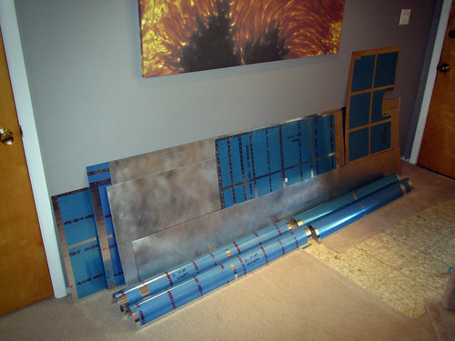
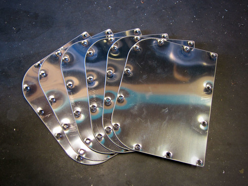
I told myself I was going to finish deburring at least one piece of either flap or wing skin every day after work and I stuck to it. The result was that this morning I finished the last of the pile of skins you see here.
That is all of the wing body skins plus all of the flap skins. The holes are all deburred on both sides, the vinyl is removed where it needs to be, and the inner surfaces have been scuffed and cleaned. The only things they need now prior to final assembly are lap joint tapers for the wing body skins, dimpling, edge deburring (which is quick), and primer.
I started with the lap joint tapers. I tried to recreate a setup like this one from Tim Olson's project, and was basically successful. I tried a 100 grit sanding wheel on my pneumatic random orbital sander at first but it wasn't chewing through the metal fast enough, so I replaced it with a 60 grit and got better results. If I had had a coarser disc I would have used it; it still took awhile with the 60.
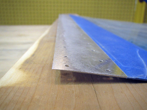
The results are a bit more abrupt than were called for in the plans, but as this is a purely aesthetic point anway and any residual ridge on the lap joints can be remediated with a quick hit of filler prior to painting, I'm not too concerned.
With this out of the way, it was time to dimple. Most of the pieces still left are somewhat unwieldy for one person, though I was able to dimple all four of the flap nose skins by myself. For the larger pieces, I had Jeremy give me a hand supporting the long end while I ran the dimpler. We worked through all four of the flap aft skins before calling it a day. The remaining task list for skins is now
One other thing that happened recently was an order in to Van's, primarily to get tank sealant for the fuel tanks whose final assembly should begin very soon now. Along with the sealant I purchased replacement torque tube parts from the aileron actuation chapter which I had screwed up on a few months ago with a bad drill hole. I was more careful with the drilling this time through and got results that I am very happy with.
The holes are round, perpendicular to the tube, and perpendicular to each other. Perfect! Unfortunately I neglected to get a new rod end for the smaller bellcrank-to-aileron pushrods so I couldn't redo that part (which was also bad, for the same reason). It'll come with my next order to Van's (sometime prior to priming).
1 Apr 2012
This is not an April Fools joke! I am done with all alodining for the wing kit!
Spent most of Saturday doing the alumiprep on numerous wing main body and right flap pieces. Today, I followed that up with alodine on all of the remaining parts that needed it.
The last chemistry step prior to final assembly, priming, will have to wait a bit because I still have a few more pieces to finish up before I can do all the priming at once. But we're on the home stretch now. Off the top of my head, here's what's remaining before I can prime:
15 Apr 2012
I'm making good progress knocking off tasks that need to be completed prior to the final wing primer pass. At this point, there's nothing but skin dimpling left to do.
I touched up the lap joint tapers on the wing skins because I wasn't totally happy with all of them and one of the inboard skins I had put the leading edge tapered corner on the trailing edge by mistake. That's all fixed now.
I went through and deburred and dimpled the flange holes in the right wing main ribs which hadn't been done yet, though this task wasn't getting in the way of the final priming pass since the ribs were already primed.
I re-visited the aileron actuation chapter to finish off a few things that I had screwed up last time. Specifically, I drilled all four ends of the bellcrank-to-aileron pushrods successfully this time. The key to not screwing this up was to use good V-blocks and make sure that everything is aligned well and clamped down properly prior to drilling. And don't use a drill that has some internal misalignment causing the bit to precess. Ask me how I know.
So the pushrods are now good to go and the entire aileron actuation chapter is complete pending primer.
I paged through the entire wing plans looking for stuff I could do that wasn't bottlenecked behind primer and landed on the Aileron Trim chapter. I had already done the bulk of the assembly for the aileron trim module, but it needed to be match-drilled to a wing inspection cover plate and have its four nutplates attached.
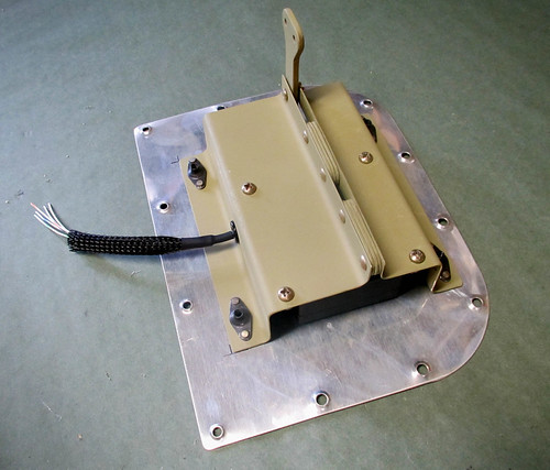
As you can see, that's done. Also, I added a bit of strain relief and some abrasion protection to the thin wires coming out of the servo. I can't finish the other end yet because I don't know what kind of connector I'm going to put on there.
At this point, I'm pretty sure that the only thing left to do is dimple all the wing skins. I got about 1/2 way through one of the big wing skins with Jeremy awhile back before we determined that we really need three people to man-handle those huge aluminum sheets effectively. So today we started in on the smaller pieces now that I'm happy with the lap joint tapers. We got the two inboard top skins done. This means that the remaining tasks prior to priming are:
21 Apr 2012
I've been bottlenecked behind getting the large wing skins dimpled but today Roger came by and for three hours we dimpled all remaining skins. That is the last of the dimpling for the wing kit (aside from a few #8 holes associated with the wing inspection panels and the pitot tube mount). This means that I am ready to do the final priming pass for the wing kit!
22 Apr 2012
Happy Earth Day! I seem to have missed the point of Earth Day, as I spent my entire morning flying down to Grants with Jeff for some pancakes, then the entire afternoon spraying toxic primer into the air and letting lots of MEK and assorted other solvents evaporate. The up side is that I have completed the final primer pass on the wings! I am now ready to begin final assembly on all remaining wing subassemblies (except the wingtips, which can't really be done at all until the rest of the wing is complete). Definitely excited about riveting again!
24 Apr 2012
Today I did some quick work finishing up all of the aileron actuation bits and pieces that I could. I started by putting the ends, rod end bearings, and jam nuts on the main pushrods:
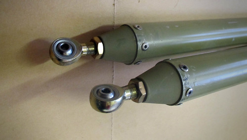
Next, I installed the newly-primed torque tubes into the forward end weldments and tighted down the nuts to 25 in-lbs:
And lastly, I added the ends, rod end bearings, and jam nuts to the bellcrank-to-aileron pushrods:
These were a bit tricky because my squeezer couldn't handle the -11 rivets (they were too long to get adequate force to squeeze them). So I built a little backriveting jig for these. I removed the bottom block from my DRDT-2 dimpler, put my AN470-AD4 cup set into the block, laid the pushrod onto the block such that one of the rivet machine heads was sitting in the cup set, then used a backrivet set to smash the rivet down. It worked pretty well though I would recommend finding some way to clamp the DRDT-2 block down to the workbench (a couple wood screws through the bolt holes would work).
25 Apr 2012
Today I started riveting ribs onto the right wing spar! Big day. Robb came over and helped me buck rivets. He was new to rivet bucking so it took awhile to get up to speed but eventually we ripped through the first 8 or so ribs. Unfortunately, in my haste, I managed to not notice that ribs 1, 7, and 11 were sitting in a different place and I put rib 8 right into rib 7's spot. Ugh. Took awhile to remove that carefully so that I wouldn't damage the spar. Nice work, idiot. After that little episode, I was frustrated with myself and stopped for the night. Here's where it stands for now:
And just for fun, here's a shot of a few of the bolts that I added on the ribs that were fully rivetd in (and in the right place).
I'm not sure why I decided to put the machine heads of the rivets on the aft face of the spar; I have a feeling that I should have gone the other way. I guess I just wanted my rivets to match the big rivets that came pre-done on the wing spar. Certainly on the inboard-most rib, there is no room for a rivet gun between the spar and the torque tube bearing bracket, so those ones will have to be machine head forward.
29 Apr 2012
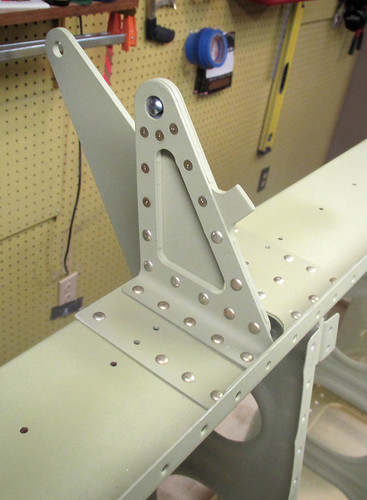
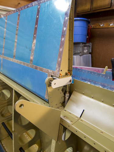
This weekend I finished up work on the right wing skeleton. I put the rest of the ribs on the spar with Jeremey's help, though I somehow managed to get #14 on upside down (?? what is wrong with me?). After fixing that one, I put in all of the bolts as required and did the 14 forward rib flange rivets for the ribs behind the fuel tanks. Turning the wing body forward-side down, I cleco'd on the aft spar and its assorted doublers and accessories. The result looked like this:
Most of the rivets in the aft spar can be squeezed, though there are a couple that I had to do with the bucking bar. Also, all of the -8 rivets at the inboard end are too long for my squeezer to effectively compress, so those ones were done manually as well. Luckily, because the visibility is so good, I was able to buck these myself. Here's a closeup of the inboard aileron hinge bracket after riveting:
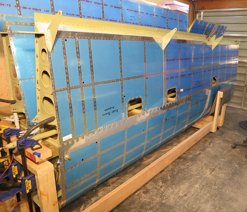
With all of the rivets done on the aft spar, that made the skeleton for the right main wing body complete so I laid the J-stiffeners in place and cleco'd on the top skins. Here's the skeleton with the first piece of skin in place:
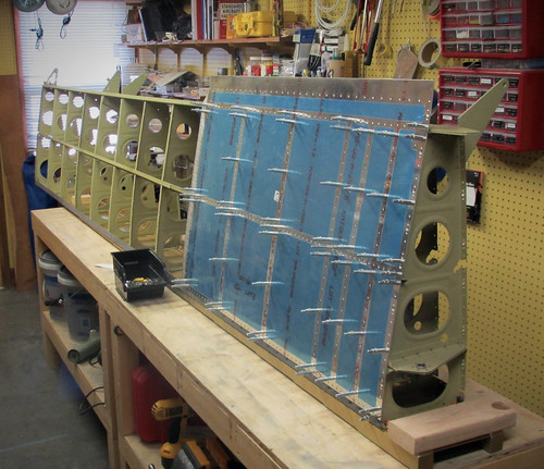
So now it's time for lots and lots of skin riveting. I've got my long backrivet sets (straight and double-offset) so I can try to back-rivet as many of these as possible for optimal surface finish. Unfortunately, I'll need help for all of these so the going may be slow.
29 May 2012
The last month has been a relatively low-output month on the RV-10; I've had to shift priorities over to training for some major mountain climbs this summer. I did, however, get some work done on the right wing skins.
These rivets require two people to do well, so I've been somewhat at the mercy of getting helpers to come over and buck. Jamie came by one night and we did the rivets you see, above, in a couple of hours. I screwed a few of them up so we called it a night and I drilled the bad ones out. He came back again a week later and in an hour we replaced the bad rivets and finished off the inboard wing skin.
A few days later, Jeremy lent a hand doing the outboard half of the outboard wing skin. Somewhere along the line, we did the 8,000th rivet in the plane!
Once everything on the wing skin outboard of the flap/aileron interface is complete, I was able to add the outboard aileron bracket as well as the aileron gap stiffener. I only got the stiffener/rear spar rivets complete; the stiffener/skin rivets should go quickly once I get around to it.
One more hour or so of riveting should finish up the right top wing skins. At that point, I'll have to decide if I want to move forward with assembly of the rest of the wing, or go back to finishing off the fuel tanks.
15 Jun 2012
The Ides of June are upon us, and the right wing top skin is done!
(sort of.) There's still 4 rivets that need to be done, which were deemed bad upon initial installation and have since been drilled out. As long as I don't accidentally install the bottom skins before fixing those 4 rivets, I am free to continue on with other tasks. The first of which is pulling the 3/4" black plastic conduit through the ribs:
This turns out to be a really slow and effort-intensive process. I got about 1/3 of the way through the wing and had to stop for awhile. I'll get back to that. Instead, I finished off the gap fairings and gap fairing stiffener:
Most of these rivets could be squeezed, except for the flush-head ones at the inboard end which were too long for my squeezer to handle, and one near the aileron/flap interface where the hinge hangers got in the way of using the squeezer.
The next steps are to finish the conduit and start on the bottom skins!
16 Jun 2012
Finished the conduit in the right wing. Holy crap that was a pain.
Definitely start running conduit from the outboard end, getting conduit through the holes in the inboard wing walk ribs that are close to each other is a real pain. I was glad I only had to move a couple feet of conduit through there instead of all 15' of it. I left a couple feet of conduit sticking out each end so that I could tend the ends later. Before I put the bottom skin on I'll probably go through and put a dab of RTV on each rib/conduit junction to prevent vibration from slowly cutting through the conduit.
22 Sep 2012
I grabbed a few pieces of aluminum and brass tubing and went up to Bob's shop to use his big bandsaw and lathe today.
First up was reaming out the aileron bellcrank bushings to 0.250" inner diameter (they ship about 0.01" too small). I purchased a hand reamer bit from McMaster-Carr for just this purpose. We loaded the bushing into the rotating half of Bob's lathe and he spun the lathe slowly by hand while I cranked in the bit.
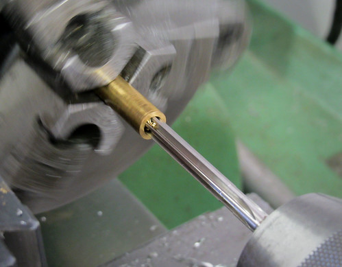
The cutting flutes on the bit weren't quite long enough to go all the way through the bushing, so I had to take out the part and reverse it. This was trivial and in relatively short order both bushings were reamed. An AN4 bolt now slides into them with no trouble at all, but there is no wiggle room between the two parts. With those done, it was time to install the right aileron bellcrank inside the main body of the right wing.
This was easy, though it was akward getting the bolt torqued down through the inspection port in the bottom skin. I couldn't easily take the bottom skin off because I had inserted the bushings into the flap hangers and they are wider than the slot in the skins. I'm going to take those bushings out before I do more aileron actuation work, but for now I was able to get the bellcrank installed through the inspection port.
23 July 2013
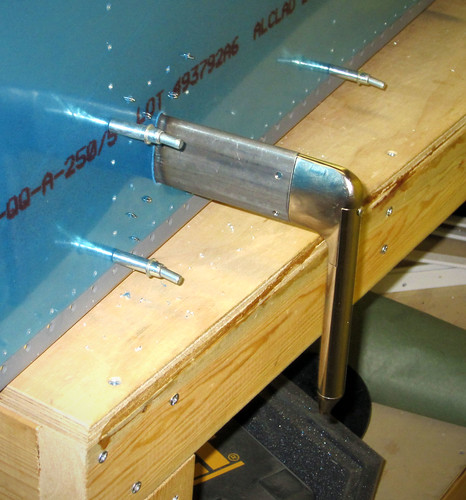
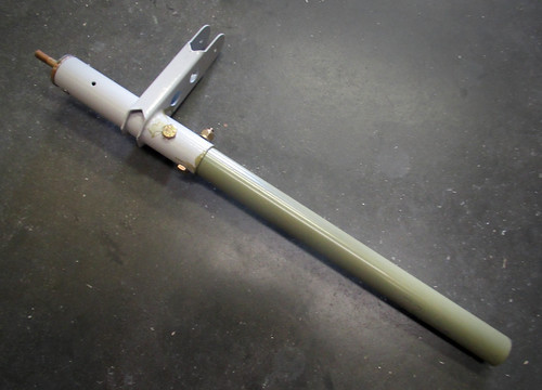
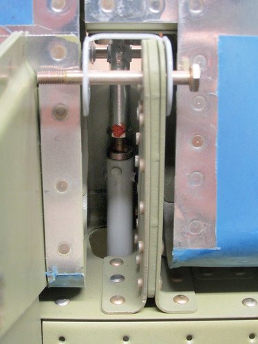
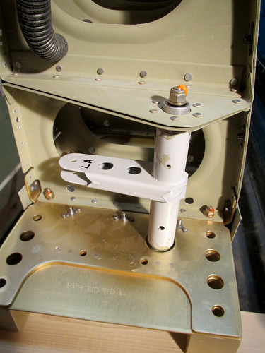
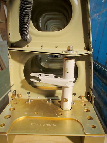
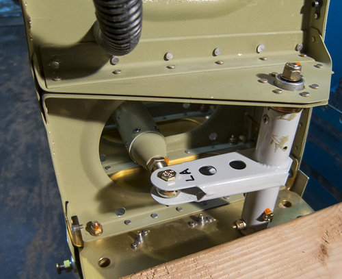
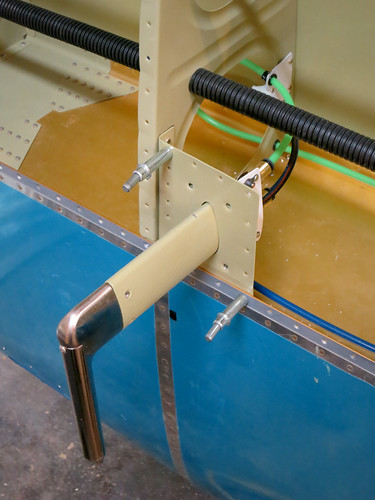
I had been waiting to install the aileron actuation hardware into the right wing so that the pushrod wouldn't be in the way of getting the fuel tank bolts torqued down. Now that the right fuel tank is installed on the wing, I went ahead and started getting the aileron actuation hardware finalized. Here's a picture of the torque tube installed in the wing root:
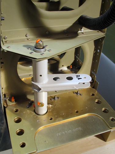
The secret to getting this in place is to jam the aft weldment way down on the torque tube, much farther than the point at which the through-holes line up. This allows the rod ends to go through the bearings at each end. Then, the aft weldment is pulled out until the through-holes line up and the weldment is bolted onto the tube as seen, above.
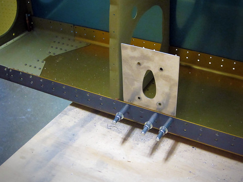
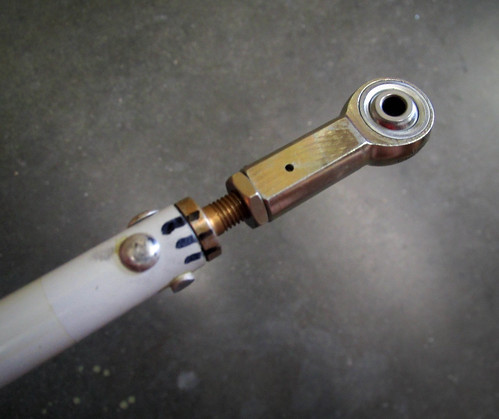
With the torque tube in place and the aileron bellcrank having already been installed earlier, it was time to install the pushrod between them and get its length set correctly. To do this, Van's offers a small jig in the kit that is attached to the bellcrank to hold it in its "neutral" position. A temporary 3/16" rod of some kind is needed to fit in the hole of the jig that lines up with the bolt hole for the smaller aileron pushrod. I used a drill bit, as seen below.
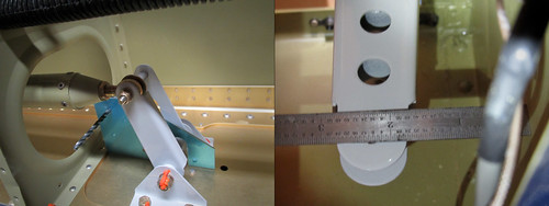
With one end of the pushrod attached to the bellcrank and the jig holding the bellcrank in its neutral position, The other end is attached to the aft end of the torque tube, and the separation between the inboard fuel tank rib and the forward end of the torque tube must be set to 2 and 9/32". This is measured to the center of the small bolt hole in the forward bellcrank weldment on the torque tube. Getting it just right required detaching the pushrod from the torque tube, loosening the jam nut, and turning the rod-end bearing in or out a few half turns. Once I had it just right, as seen in the picture above at right, I torqued down the jam nuts on both rod-end bearings, installed the bolts at each end, and put torque seal on everything. The main pushrod is installed!
A similar system is used to correctly set the length of the smaller aileron pushrod that connects the bellcrank to the aileron itself. Here is a picture of the bellcrank with both pushrods installed:
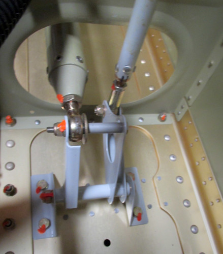
And here is the other end of the aileron pushrod as seen from below:
It turned out that this pushrod I had at exactly the right length to keep the aileron lined up with the flap when the bellcrank was in its neutral position, so it needed no adjustment at all. I went ahead and torqued down the jam nuts on the pushrods but left both bolts at either end in a temporary configuration so that the aileron will be easy to remove.
1 Aug 2013
The right wing is starting to look very complete (as long as you aren't looking at it from the bottom, where it is still missing quite a bit of skin, or from the outboard end, where it is obvious that the wingtip is missing...).
I looked through my electrical system plans to see what sort of wiring needed to be done in the right wing and found that almost all of the electrical devices are either in the wing root or at the wing tip, with the exception of the autopilot servo and the outside air temperature sensor. The AP servo has to go in the bellcrank bay of the main body, but the OAT sensor can basically go anywhere, so I figured I'd just put it in or near the same bay, meaing there was only one place in the middle of the wiring conduit where wires had to be extracted. I took an exacto knife to the conduit a ways outboard of the bellcrank and left the following hole:
I haven't committed to a particular AP servo yet, so I don't know what sort of bracket I'll need to get/make for it. Until I know for certain, it'll probably mean I don't attach the outboard bottom wing skin. For the time being, I don't need to run any wires; I'll probably get to that when I do the wing tip. I can go ahead and attach the inboard bottom wing skin, though, so that is now green lit and on the list of things that could happen whenever I have a suitable assistant. In the meantime, the right wing sits mostly-complete in the garage.
14 Sep 2013 Started the final assembly of the left main wing body. The first step was to cleco together all of the ribs, the main spar, the aft spar, and the various doublers and aileron hanger bits that attach to the rear spar. From there, it was straightforward to rivet the ribs to the main spar without help. Here's the result:
Riveting the rear spar on was even easier, as most of it could be squeezed. At the thick inboard end some of the rivets were too long for my squeezer to get ample purchase and I had to use the rivet gun. There were a couple there that came out bad and had to be drilled out. In the process, I managed to snap a drill bit. More items for the Jar of Offerings to the Gods of Flight:
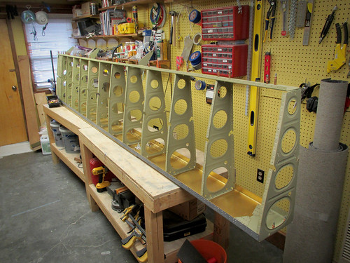
That aside, I did manage to get the full skeleton for the left wing fully assembled. Here it is prior to me hanging the skins on:
I've got the top skins cleco'd into place now, but will need to find an assistant for that part.
27 Oct 2013 I once again allowed myself to get bottlenecked behind a task that required multiple people, and use that as an excuse to spend every weekend and evening doing other things. Until today. I finally got my friend Will to come by and help me buck rivets. As someone who has built multiple experimental aircraft in the past, he knows his way around a bucking bar and was really fast. We blew through half of the rivets on the left wing's top skin in about two hours.
After he left, I squeezed the inboard row of rivets (along with the 8 nutplates) since this could be done solo. He's coming back in a couple days and hopefully we'll finish off the job. At least some forward motion has occurred this month...
30 Oct 2013 Yesterday after handball, Will came over and we finished off the top skin rivets on the left wing over the course of two hours. Everything goes so fast when you have a good helper!
This evening, I put the pre-assembled outboard aileron bracket in place and did its 10 rivets solo, then added the gap fairings and riveted them in place.
It turns out that I had neglected to countersink the inboard-most holes for the gap fairings on the rear spar, so I had to do that first, but it was not a problem and now the gap fairings are complete. I inspected everything and found one skin rivet I'm unhappy with. I'll be drilling that one out and re-doing it next time Will comes by. I forgot to mention it in my last post, but somewhere in the middle of the outboard wing skin was the 12,000th rivet in the airplane.
7 Nov 2013
I was dreading putting the wiring conduit into the left main wing body because it had been such a pain on the right wing. However, when I set about pulling it through the holes in the ribs, I found that it was actually quite easy to get through rather quickly this time. No idea what I was doing wrong this time, but with some effort I was able to pull significant lengths of conduit through each hole in a single pull. I did manage to put a few good-sized blisters into my hand doing this, so my recommendation is to wear gloves. The only hard part is getting the narrow wing-walk bays pulled, since there is no room there to pull parallel to the conduit. I probably spent more time getting the conduit through those three bays than I did getting the whole rest of the wing rigged with conduit. No photos.
16 Nov 2013
Will and I tackled the right wing's inboard bottom skin. I clecoed the aft half of the bottom skin into place, then tied some safety wire between the forward edge of the skin and the flap hangers to pull it up and away from the wing body. This allowed will to get an arm into the inside of the wing and buck rivets at the aft end of the wing.
The farthest-aft rivets were a real pain (for the bucker, anyway; driving them is easy). The plans indicate that we should start at the center of the aft spar and work forward and out to both sides of the skin. I wanted to get the entire aft half of the skin done before moving on to the forward half so that I could keep the safety wire bend in place. However, when we got to the point of having to get an arm inbetween the wing walk ribs we found that neither of us was able to do it; our forearms wouldn't fit in the narrow bays. We resolved to get Will's daughter, who is working on her A&P certification and loves sheet metal work, to come by next week sometime and help.
26 Nov 2013
Will and his daughter April came by this evening and the three of us set to work getting the really awkward rivets in the wing walk region of the bottom inboard skin on the right wing completed.
Will was the official rivet inspector, I handled the rivet gun, and April had the thankless job of getting the bucking bar aligned with the back of the rivets, blind, in a very confined space. We did pretty well, with only a couple rivets needing to be drilled out. The entire aft half of the inboard skin is now complete, leaving the somewhat less-constrained forward half remaining. I told April that she would have to fly back out from New Jersey when I got to this point on the left wing. I have no idea how the people who have done this section solo have managed.
1 Dec 2013
I wanted to see how many of the inboard bottom skin rivets I could do solo now that the more-difficult aft half was complete. They were all challenging, and it went really slowly because I had to check each rivet awkwardly with a mirror and flashlight, but it turns out I was able to get all of them done myself!
This felt like a real accomplishment for whatever reason. And for those of you who are counting, the 13,000th rivet in the plane is somewhere on that skin panel.
I went ahead and hung the outboard skin and cleco'd the aft half in place, as can be seen in the photo above. I won't be trying to solo those aft rivets, even though all of the outboard bays are wide, because the reach is too extreme for me to reliably rivet. I'll wait until Will can come back to start on those.
12 Dec 2013
Will came over after handball tonight and we started attacking the rivets on the right wing's outboard bottom skin. This piece is nicer than the inboard piece because all of the bays are wide, but it's twice as long so it's going to take awhile. Of the sixteen "panels" on the skin we were able to finish off three, starting at the aft center and working inboard.
It'll probably be another couple of visits from Will before the aft half of this skin piece is fully-riveted. I'm going to try to do most of the forward half myself again, though this one is more difficult because there are some bays that are quite a ways from the nearest access panel. Furthermore, for some reason the 14th (second-to-most-outboard) rib has inboard-facing flanges, meaning that it's not facing the closest access point for bucking (which would be through the outboard rib's lightening holes). Not a huge deal, just a pain. I might not be able to solo all of that; we'll see.
16 Dec 2013
Will came over again and we worked on more of the skin rivets. We managed to get to the point where the inner 3/4 of the aft half of the skin was complete.
This allowed me to go ahead and cleco down the forward half of the skin on the inboard side and start working those rivets solo. It's a lot slower going by myself, so I only got one panel done in an hour. Seven of the 16 panels are now done on this piece as seen in the photo, above.
18 Dec 2013
With the left wing now in the garage and with the fuel tank attached, I was anxious to get going on the aileron actuation hardware inside the main body. The section was pretty quick on the other wing and is nicely divisible into a bunch of small tasks, so I decided to take a stab at it during my lunch break today. First up was the aileron bellcrank weldment install.
This installation went really quick, probably because there's only five new parts including the bolt, nut, and washer. Total time spent: less than five minutes. So I decided to move on to the next bit, the torque tube.
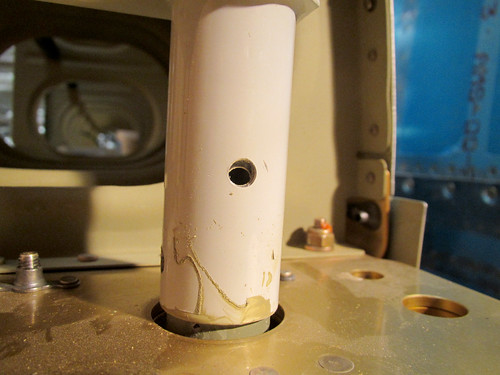
This section also goes pretty quickly because the bulk of the work on the torque tube had been done ages ago in pre-assembly. I got the tube threaded through the hole in the spar and the aft end put on to test the length. It looked like this:
The next step is to check the bolt holes that connect the aft torque tube weldment to the torque collar inside for misalignment. There had been none on the right wing, but this time there was a few millimeters of offset:
This isn't a huge deal; the plans specifically call it out as a possibility and give the cure: add a washer between the torque tube and the bearing to force the weldment in the correct direction. To do this, I had to remove the weldment from the bearing. It turned out to be really stuck in there. All the pulling in the world wasn't getting it free. So I tapped on the end of the threaded rod and this happened:
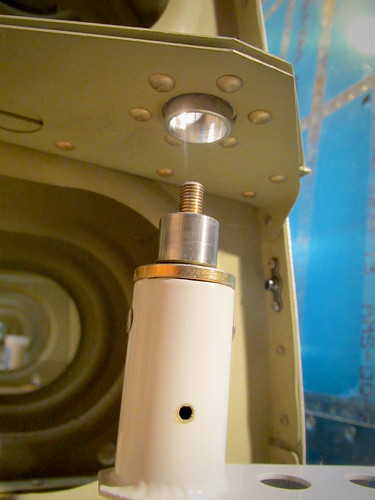
The bearing core popped right out of its housing! I didn't even know this was possible. Oddly, once the core was out of the housing, the core slipped off the threaded rod-end easily. No idea what that's all about. But I was left in the situation of having the bearing hardware separated, and the tolerances between the core and the housing were so tight that I couldn't get it back in there by hand.
I wasn't sure what the best plan would be so I consulted some friends that are mechanically-minded after work and got a range of responses that were all either recommending using an arbor press, using something that simulates and arbor press, or freeze the core and heat the housing and try to mash them together by hand. I don't have an arbor press and the whole tempreature manipulation angle seemed overly complicated for a first attempt, so I went to the hardware store and bought a machine screw, two washers, and a nut.
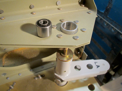
The basic idea here is to get a long 1/4" machine screw (this one was 3.5" long), a nut for it, a couple of washers, a socket that just fits inside the bearing housing (7/16"), and one that just barely doesn't fit inside the housing (9/16"). Both sockets need 1/4" arbors. The screw goes through the arbor end of the socket such that the head of the screw sits on the back face of the socket. Next, the bearing is pushed onto the screw until its outer race on one end is up against the open end of the socket. This is then placed on the bearing enclosure as shown in the left side of the picture above.
Initially, I just put some washers wide enough to be wider than the opening of the housing on the bottom, then threaded on the nut as shown in the center of the picture above. By tightening the nut, the washers sit flat against the bottom side of the housing. Since the top face of the nut is parallel to the bottom face of the screw, which is in turn parallel with the face of the socket and thus the bearing, as soon as the washers are pressed against the bottom of the housing, the bearing is kept in perfect alignment with the axis of the housing.
There is a slight bevel to the edges of the bearing and housing, so applying more pressure caused them to become co-axial, and then the bearing slid nicely into the housing with no trouble as the nut was tightened on the screw.
The only remaining problem was that the washers on the bottom made contact with the inner race of the bearing before the top part of the bearing was flush in the housing. So I took the nut and washers off and stuck a larger socket on the bottom which would only contact the housing and allow the bearing to be pushed farther down (see the right-hand photo). Once the bearing was at an appropriate depth, I released the pressure on the nut and removed all the hardware and it was just like new. Whew! Thanks to everyone who offered suggestions on how to get this done. I'm glad the solution didn't involve dry ice and blow torches.
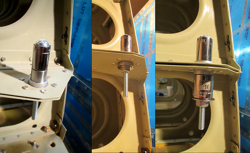
With the bearing back where it should be, I re-assembled the torque tube in place, now with the spacer washer.
This introduced another problem, albeit much easier to solve. With the spacer washer in place, there is no longer any thread on the rod-end sticking out the end of the nyloc nut at the aft end of the torque tube (as seen in the picture, above). This will be easily solved by replacing the outer washer with a thinner one which I have in stock. However, at this point, I have put that nyloc on and taken it off several times as a result of all the bearing shenanigans. So I need to replace the nut and I'm not sure if I have any of those left. Not a big problem as it is easily accessible and this replacement can be done at any time.
Anyway, what should have been a quick 10 minute job turned into over an hour of work today but I learned some cool new techniques. I'll leave the pushrods for another day.
4 Jan 2014
With the minor fiascos of the left wing torque tube out of the way, I set about getting the pushrods temporarily installed and sized. Stared by attaching the main pushrod to the torque tube with a temporary bolt:
Next, I attached the other end of the main pushrod to the left aileron bellcrank and held the bellcrank in its neutral position with the provided jug plate. By then measuring the position of the torque tube relative to the fuel tank inboard rib, I could set the length of the pushrod to its final value and lock it in place. Once this was done, I attached the aileron to bellcrank pushrod to the bellcrank temporarily. The result looksed something like this:
The other end of the smaller pushrod got temporarily attached to the aileron itself, which had also been temporarily attached to the wing:
To set the final length of the smaller pushrod, I need to get the aileron into its neutral position, which requires the flap to be in place, so that'll come a little later.
26 Jan 2014
Will came over today to do the bits of the right wing bottom skin riveting that I couldn't do solo. We had all the hard bits done in about two hours then went to lunch. Later in the afternoon, I went back and finished off a few dozen easy rivets that were remaining and attached the nutplates to the access plate holes. This completes the bottom skins for the right wing!
This also means that the right wing is now structurally complete with the exception of the wingtip. Big milestone! Of course, there's still the entire bottom skin for the left wing... but there's plenty of random internal stuff to do on that wing before we start the rivet extravaganza again.
21 Feb 2014
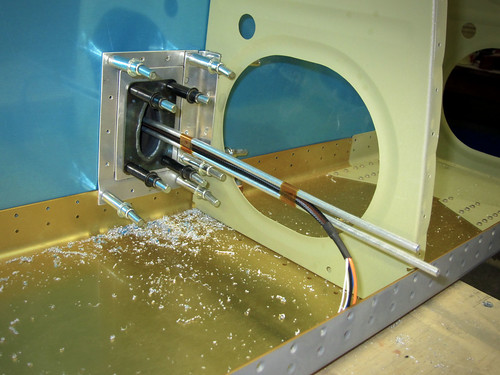
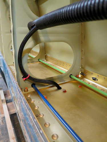
Back before final assembly of the left wing, I laid out a plan for the internal wiring and plumbing which required the drilling of a lot of small holes in the forward ends of the ribs in order to pass the two air lines required for my pitot tube and AoA sensor as well as an antenna for my APRS rig. Today I went ahead and populated the shap bushings in each of those holes and ran the plumbing and antenna cable.
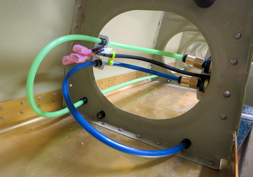
This particular photo is of the bay just outboard of the aileron bellcrank, which is where the APRS antenna will be. The brass circular thing at the end of the RG-58 cable is an NMO universal radio antenna mount. It'll get mounted into the bottom skin once it's on (through a custom 3/4" hole), but for now it'll just lay on the spar until I can get the skin riveted in place. The green and blue lines are my AoA and pitot air lines. These plastic tubes run from adapters at the end of the pitot tube's integral metal air lines in the outer-most bay of the wing to a bulkhead union coupler in the outer skin of the fuselage within the wing root. For now the tubes just hang free at both ends of the wing awaiting installation of the pitot tube (after the bottom skins are on) and attachment of the wing to the fuselage (a long, long time from now in a galaxy far, far away). There was some concern on my part that the air lines might interfere with either the aileron bellcrank or the torque tube in the wing root, but it turned out to be unfounded.
As you can see, the air lines clear the aileron bellcrank with plenty of space. The same is true of the torque tube, though there will probably be some interesting air line routing within the wing root to ensure that there aren't any problems.
One other thing that happened today was getting the three inspection panels installed on the right wing now that it's essentially complete.
28 Mar 2014
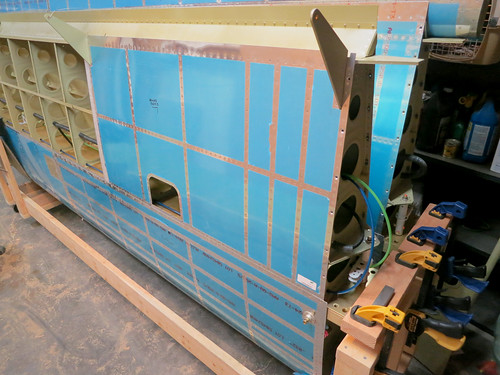
I spent some time this month on travel so I haven't gotten much done. However, I did get the inboard bottom skin cleco'd in place on the left wing and bent up with safety wire.
So I'm ready to rivet that piece in place as soon as I have someone to buck the rivets.
8 Jun 2014
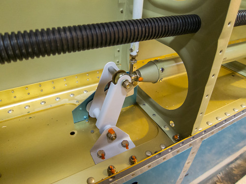
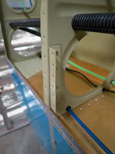
The day's work focused on the theme of preparing for the bottom skin on the left wing. I realized after my last entry at the end of March that there were still a few small tasks that needed doing before the bottom skin was on. First was some work on the pitot tube mount. The bracket that attaches the doubler to the rib was ready to be riveted in on the rib side, so I went ahead and did that. Here's a picture of it installed:
Then I riveted on the nutplates that sit on the top of the pitot mast and are used to attach the skin, doubler, spacer, and mast together. Here's what they look like:
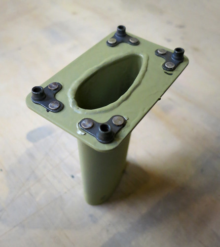
And just for kicks, I stuck the mast, spacer, and doubler in place on the bracket and clecoed them in just to see what it would all look like.
The mast, spacer, and clecos will have to come out of there before I can put the bottom skin on, but the doubler gets riveted in place along with the skin so it's where it needs to be from now on.
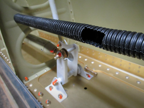
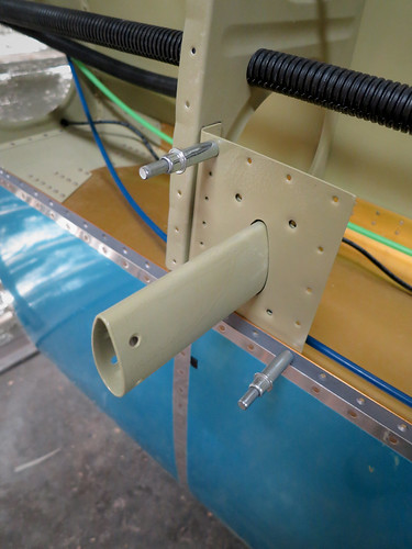
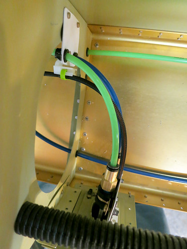
The next bit to take care of that had to be done prior to riveting on the bottom skin was to tend the cable bunding coming through the main spar from the leading edge. I already had it encased in a protective sleave, so I cut a hole in the main wiring conduit and fed the bundle through to the wing root.
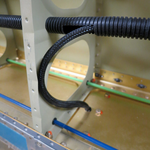
I left the curve in the bundle for two reasons. The first was to ease the transition in direction going into the conduit, the second was to clear the way for the aileron pushrod which needs to move back and forth in the largest lightening hole seen above. I'll probably put a little adhesive wire tie anchor on the face of the rib where the bundle meets it at its lowest point (left-most in this photo) and secure it there. However, to keep it out of the way for riveting on the skin, I'll likely add the wire tie after the skin is already riveted down. The bay one inboard from this one has an access panel that should make this feasible.
The last task prior to adding bottom skins was to cut another hole in the conduit to service the aileron trim servo wiring. This is in the same bay as the inner-most inspection panel and looks just like the hole I cut in the photo above. With that complete, I'm ready to rivet on some skin. Just need to get a helper over to buck, and that's scheduled for tomorrow evening.
9 Jun 2014 Will came by tonight to have a look at the progress on the left wing and help bang out some rivets on the inboard bottom skin. We managed to complete all of the easily-accessible rivets on the aft half the skin. After confirming that neither of us could get a buckingbar up to the rear spar inside one of the narrow wing-walk bays (our fists are wider than the space available), we called it a night.
10 Jun 2014 Yesterday I showed Will what I was thinking for installing the pitot tube and the plumbing behind it and he expressed some concern that having the somewhat massive tubing adapters suspending out in open space supported by soft aluminum tubing was a recipe for tubing failure. He recommended that I connect the adapters to structure somewhere/somehow. I spent some time deciding how best to accomplish this, and today I implemented my solution.
The first step was to shorten the aluminum tubes coming out of the pitot tube to the point that the adapters would just barely be above the mast. After cutting and re-flanging the tubes and re-installing the adapters, I set about building a small custom bracket that would rivet onto the top of the mast base and to which the adapters could be secured with adel clamps. Here's a photo showing the final parts separate and assembled:
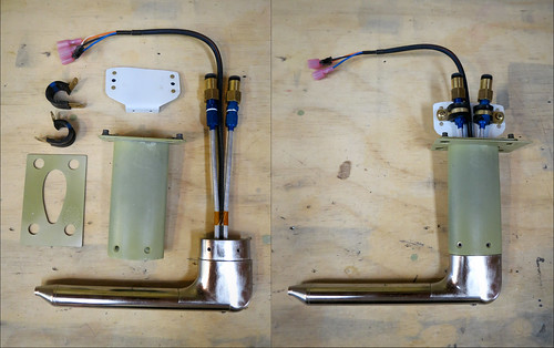
Once those adel clamps are tightened down, there will be no movement in the aluminum tubing at all even in a high-turbulence environment. The clamps have to be removed to get the pitot tube in and out of the mast, which means that for final assembly once the bottom wing skin is on, I'll have to attach the clamps through the wing rib lightening holes from the outboard end of the wing, which will be a pain. But unless something goes terribly awry, I should only ever have to do that once.
With the new plumbing layout above the pitot tube, the plastic airlines now leave the adapters heading straight up and need to make a big turn to loop around to the current plumbing run along the aft surface of the main wing spar. I decided that to keep the loops of tubing as secure as possible, I'd loop them around to the outboard side, through the rib's lightening hole, and back around to the existing snap bushings in the base of the rib. To do this, I'd have to make a bracket to keep the tubes (and the heater wiring harnes) safe as it went through the lightening hole. Here's the simple bracket I ginned up:
It's just another pair of plastic snap bushings for the air hoses and a wire tie hanger for the wiring bundle. I installed this to the top of the largest lightening hole with a pair of rivets.
Next, it was time to test-install everything to make sure my solution made sense and that there weren't any engineering details that would bite me and had to be fixed before the bottom skin went on. Here is the view from the bottom of the test install:
Here's what it looks like from the aft:
...and from the outboard:
...and from the inboard:
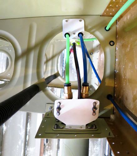
All of the tubing and the wire bundle are kept from rubbing on anything and there is some strain relief on the adapters in case I do something stupid like yank on the tubing from the wing root end during installation of that end. Happy with the installation, I disconnected the tubing from the pitot tube and removed it. It's in storage now until the bottom skin is attached.
15 Jun 2014 Yesterday and today I finished off the left wing's inboard bottom skin. The aft half had already been completed thanks to bucking assistance from Will and Nina. I was able to do all of the forward rivets solo since there is a lot more room to manuever in the wider forward section of each bay. Somewhere in here was the 14,000th rivet in the airplane!
The next thing I did was to go through my list of custom bits on the left wing as well as all of the internal mechanisms, plumbing, and wiring and make sure that there wasn't anything else that needed tending to before I put on the outboard bottom skin. The one item I came across still needing done was to add a wire tie anchor that would keep the stall warning switch wire bundle out of the way of the aileron pushrod. Here's a shot of a test-install of the anchor:
Of course, having the wire bundle over there makes it in the way for getting the bottom skin on, so I took the wire tie back off and pushed the bundle back to the center of the bay. Once the skin is on, I'll re-attach the wire tie (blind, through the access panel that is one bay away). Shouldn't be too painful.
Having confirmed that everything internal to the wing was complete, I went ahead and hung the outboard bottom skin in place--the last piece of skin in the wings! It is ready to be riveted, but that'll have to wait for another day.
Time invested on this sub-assembly: 166 hours (135 by me)
Updates regarding the wing bodies
24 Nov 2010I started working on the first chapter in the wing plans, which covers the main wing spars. Unfortunately, it accomplishes almost nothing before needing a small amount of priming. I got the extensions and their splice brackets matched drilled and deburred, which made them ready for priming. Then I skipped ahead a bit and match drilled the two tie down brackets. My wee bandsaw wasn't hearty enough to trim the brackets to length, so I went to Bob's shop to use the megasaw. Cut through it like butter.
With these few parts ready for priming, there was nothing left to do in that section without first priming these bits, and I didn't want to deal with the overhead of priming for just 12 small parts. So next I'll continue on with some other section and get additional parts ready for priming.
23 Jan 2011
Right main spar marathon.
Priming done, it was time for some riveting. I decided to go back to the first chapter of the wing kit, the main spar, and continue again where I had paused pending priming. This meant riveting the spar extensions and doubler plates in place.
These all required the gun and bucking bar, but were easy enough to do by myself. I did the extensions for both spars. I decided to continue onwards with the main spar chapter, doing the right spar first since it was the one still sitting on my workbench. The next step was to match drill the holes in the wing box J-stiffeners.
This was pretty straightforward and took less time than I thought despite the multitude of holes.
Speaking of holes, the next few steps were all about countersinking. Every single hole in the flange of the spar gets countersunk (except, I think, the "extra hole" in the bottom of the extension on each side). That's about 52 linear feet of flange with a couple holes per inch. This took forever, and I only did one of the spars. The outcome, however, was awesome.
In the above shot you can see that I've already put in the fuel tank attach nutplates as well, so the flanges are basically complete here. The only task remaining on them is to spot-prime those enormous countersinks. I haven't decided how I'm going to do that yet, and it isn't critical path until the time comes to attach the leading edge to the spar (which is a long way off), so I'm tabling that step for now.
Here's another view where you can see the plethora of nutplates:
I spent most of the day between the flange nutplates and the countersinking. When that was all done, there was a short encore for the wing root area, where there just five more nutplates to do and three random rivets.
For the life of me, I couldn't find where in the plans it says to actually attach the "wing attach nutplates" on the right side of this image. The diagram shows them going on here, but the text does not. As you can see, I went ahead and put them on. I hope that doesn't bite me in the ass when it comes time for wing attach, later...
The last little bit of work involves the tie down block and aileron bellcrank bracket. These were quick to install. Here's the brackets:
And here's the tie-down:
As you can see, I neglected to actually do the rivets. I got so excited about being done with one of the spars that I put away all my tools before realizing I hadn't finished this step. Oh well, I'll finish that up next time. It's just 10 rivets anyway. Here's the final shot of the essentially-done spar:
Tim Olson was right when he said that this section was a bit frustrating in that you do tons of work and in the end it doesn't look much different. The bits that are obviously different (the extensions and the tie down/bellcrank bracket) were by far the quickest to do. Oh well. I'm still pumped to have this behind me.
30 Jan 2011
Still waiting on help with the riveting of the right leading edge, so I set it aside and hauled out the left main spar. Over the last three days I've managed to get it almost complete.
There's nothing significantly different about this one than the right-side one that I did last week, so I didn't take much in the way of pictures. All that is left at this point is to spot-prime the countersunk holes.
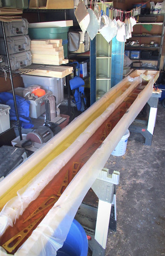
5 Jun 2011
With the leading edge finally off the workbench, I had room to get the second wing spar up on the tables and prime its flanges. This was the last step left in the main spar chapter of the plans, so with those done I moved them into the garage for storage. They won't be needed again until I have the cradles built and am ready to attach the leading edges and fuel tanks to the spar.
18 Jul 2011
For a change of pace, I did a bit of get-ahead work on the aileron actuation chapter of the plans. There are three main assemblies that need attention prior to a priming pass—the torque tubes, the main pushrods, and the bellcrank-to-aileron pushrods.
The main pushrods just require a cut-to-length and match drilling the end pieces on. I had Bob do the cuts for me on Pat's huge bandsaw. The match-drilling and deburring took no time at all.
The smaller pushrods require a length cut, which Bob took care of for me, and then some match-drilling that needs a V-block (which I don't currently have), so they're on hold.
Each of the two torque tubes is composed of two end weldments, two threaded inserts, and a collar connecting them. Bob cut the collar stock for me, and I match-drilled and riveted the threaded ends into the weldments.
For some reason, the threaded ends get riveted in prior to priming as per the plans, and only the forward ends and the collar get primed (??). Not sure if that's an omission in the plans or if there is a good reason.
25 Jul 2011
I did a couple of minor things today. First I deburred and dimpled the last of the aileron skins so they are all done now and ready for final assembly.
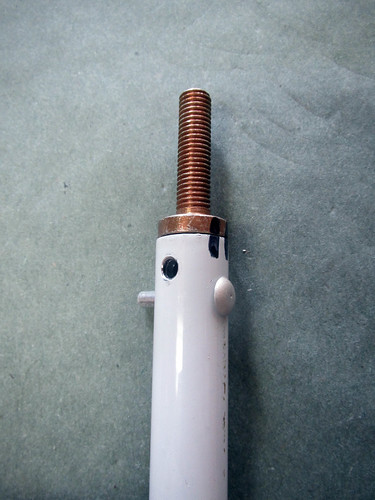
Next, I picked up my cut torque tube collars and replacement fuel sender access panel cover (I had mis-drilled one of the ones I made before) from Bob. When I got home from work, I set to work continuing the aileron actuation chapter by putting together the forward torque tube assemblies. The first step here was to match drill the weldments into the torque tube collars.
This went without a hitch. The next step was to drill #12 the matched holes out so that a AN3 bolt will fit through. On one of the torque tubes, this went flawlessly:
Unfortunately, on the other one, I managed to get the drill out of alignment somehow and made a huge oval out of one of the holes in both the collar and the weldment. So that piece is ruined. At a minimum, I'll need to order a new weldment ($60) and a new piece of the pipe ($20). If I can't get the pop rivets out cleanly, I'll also need a new end cap ($8). With shipping, I'm looking at about $100 for a botched drill job. Ouch. Probably the most expensive mistake in the plane thus far.
1 Aug 2011
I started the wing ribs chapter this past weekend because I had convinced myself that they would need to be completed before the fuel tanks. The first bit was fluting and flattening all of the ribs. Nothing photo-worthy there... Next was getting the torque tube bearing brackets match-drilled for the inboard ribs.
I ended up needing a larger bandsaw than I have to make the cuts for the angle pieces that support the bracket (the required width is about 1cm too big for the throat of my bandsaw), so these bracket assemblies aren't quite done. But they're very close. I also got the flap hangers done on each of the three ribs that they attach to, but didn't take any pictures of that. The exception to this was the reaming of the flap attach holes, which I'm also saving for a trip to Pat's shop because I don't have any reamer bits.
From the aft spar chapter, I went ahead and did the aileron hinge brackets as well. These were quick, but again I needed a beefier bandsaw to cut off the tabs on the outboard brackets, so they're not quite done either.
So there's not much left on the wing ribs; just a few fabrication steps that need to happen elsewhere, and a bit of follow-up once those pieces are cut. Then there's just two major steps: match-drill all the ribs to the spars, then deburr/dimple everything. I may also go ahead and figure out how much I want to drill out the wiring and plumbing holes and do so before the priming (despite the plans' doing this after priming).
8 Aug 2011
I got the angle pieces cut for the forward torque tube brackets, got them match-drilled into the ribs and brackets, and then enlarged the conduit holes using a unibit.
I noticed that the holes in my ribs are all lined up, whereas Tim Olson's seem to be offset after the first one. I like this arrangement better and hope that the straight-through 3/4" plastic conduit won't interfere with the aileron bellcrank. Eyeballing it, it seems like it should be fine.
I went ahead and continued with the wing ribs chapter, attaching all of the ribs to the spars in order to match-drill the holes they share. The beginnings of a wing shape in the shop was exciting.
28 Aug 2011
Back in town after a work trip. Finished off the fluting of the wing ribs, the match drilling of the wing ribs to the spars, and the deburring of the freshly-drilled holes in the spar.
I took the flap hangers up to the airport where Jeff let me use his 3/8" reamer bit to finish off the hinge holes, rendering those parts ready for surface chemistry.
11 Sep 2011
It has been an epic weekend of plane progress! On Saturday, Jeremy helped me finish off all deburring and dimpling tasks required for the next round of surface chemistry and priming. This included all of the wing ribs and fuel tank ribs as well as numerous smaller pieces.
With that, it was time to do another iteration of the Alumiprep/Alodine/Akzo chemistry fiesta. The trouble was that my dunk tank only accepts long/narrow pieces so I had to construct something that would fit the wide wing ribs in it. After a moment of considering building a new tank, I had the brainwave of just removing the center rail from my existing tank and installing some beams that go across the tank the short way, dividing it up into three 1.5 x 4 foot tanks.
Perfect. The only problem with this arrangement is that I can only fit two wing ribs in a given bay at a time, which means at least 15 cycles through the process to get all 30 wing ribs done plus additional cycles for the tank ribs, though these fit four at a time (and you can get a single tank rib in with the two wing ribs, too). Other than the fact that I had a ton of parts to run through the chemistry processes, everything went smoothly. I probably should have started earlier than 7pm on Saturday... because it took me a little over six hours to finish everything. Went to bed at 2am. Wow.
After sleeping in a few hours late, I set about priming all of the non-fueltank parts this morning. Immediately ran into a snag: the primer from the last pass had not been cleaned out of the spray gun effectively and had solidified. It was unrecoverable. So I ran to the hardware store to get a replacement spray gun, only to find that the generic one they had at half the cost of my old one was significantly better! Win. I also found that I'm just about out of my first cans of Akzo. Hard to believe that a gallon of primer has already gone into this thing. I suspect I'm using it too thick or wasting a lot. Anyway, the priming went reasonably quick. Misjudged the amount I'd need twice, so had to make three batches. Luckily, the third batch was almost exactly used up on the last parts.
For the first time, I did the priming out in the driveway because the weather was nice. This meant I didn't have to waste time turning the shop into a paint booth, fog the room with fumes, or wear a silly outfit to get the job done. Got some weird looks from joggers running by as I went to work wearing my respirator and goggles... but whatever. The sun dried the primer in just moments so the whole thing went very fast.
I immediately started riveting together those subsections that were now ready. First up was the aileron trim module. The housing went together quickly:
And the servo mounted into the housing:
Next up were the wing ribs that had flap hangers at the aft end. This includes the inboard ribs, which also have the torque tube support bracket and bearing:
Lastly I did the aileron hanger brackets. I already knew that I had accidentally countersunk two extra holes on the inboard units; this wasn't a problem because I can just use 426 rivets in them and they'll work fine. What I didn't realize until I sat down to rivet them was that I had forgotten to countersink the outboard brackets at all. So this was done and then the parts were riveted together.
With these subassemblies done, I went through the wing plans checking for anything else that could be done out of order as get-ahead work and came up empty. So now it's time to clear the work benches and get ready for the top skin and aft spar sections! Soon, I'll have to build a rolling cart for the wings.
14 Sep 2011
With the ribs primed and their accessories riveted in place, I took some time to assemble the rest of the main wing box. I clecoed the ribs to the main spar and then attached the aft spar on top of the ribs.
The plans call for you to rivet the ribs onto the main spar before proceeding to the aft spar, but I'm not sure why. In the interest of saving some space for awhile, I'm going to go quite a ways ahead in the plans with just clecos so that I can get all of the match-drilling, deburing, and dimpling out of the way. So, after the aft spar, I went ahead and put the top skins on, then the gap fairings, then the aft skins.
The plans make a big fuss about not match-drilling this row or that because of some later part that needs to be added, but by pre-assembling all of these parts, pretty much all of the holes are now ready for drilling. Over the coming days, I'll finish all of the match drilling, deburing, and dimpling on the left wing box and then can fully disassemble it without having to store it in its bulky form. There's no real accessory work that needs to be dealth with until I've actually riveted the main spar, ribs, aft spar, and top skin sections together. But before I get there, I'll need to have done the final priming pass on the long parts. And before I do that, I'm going to get all this preparatory work done on both wing boxes as well as the flaps.
19 Sep 2011
Did a bunch of drilling on the left wing box over the last couple days. All of the holes in the top skins are now drilled (with the exception of the wing tip attach holes). I also drilled out the gap fairing to rear spar holes, which rendered both left gap fairing pieces ready for deburring. These were removed and set aside for later. All of the holes in the top skin that go through the wing walk stiffeners were countersunk as well as all of the screw holes on the inboard edge except the aft-most one, which was dimpled for #8.
So at this point all the drilling is done for the gap fairings, the top skins, the wing walk doublers, and the rear spar components. Just the bottom skin drilling remains and should go quickly as there is very little countersinking on that side. Then it'll be time to disassemble and debur everything, then do it all again on the right side.
27 Sep 2011
Finished up all of the match drilling on the left wing! Doesn't look any different, but all of the skin parts, the rear spar assembly, and the skin holes on the ribs are all ready for deburring and dimpling. I also ripped out all six of the wing access covers.
These were pretty quick, just final drilling each hole, deburring the holes and edges, then dimpling. They're all set for surface chemistry and priming on the inner surface. Time to disassemble the left wing!
8 Oct 2011
Today is the second anniversary of the arrival of my empennage kit! Two years in and I'm about half-way done with the wings. Like I've said before, this is not a speed-build.
Today was all about the pitot tube. My Dynon heated pitot/AoA probe arrived in the mail last week, along with the matching Gretz mount kit (and my Bob Archer NAV antenna and some more Akzo).
I had been spending a lot of time recently deburring the outer face of the skins of the left wing, and yesterday I finally got to the point where the outboard bottom skin was ready to come off. With the skin off, I had access to the areas I needed to begin fabricating the pitot doubler and its accessories.
The doubler that comes with the Gretz mount has a joggled end piece that goes on the inside of the aft row of rivet holes in the main spar flange. The only questions is where along the spar to place the pitot tube. Gretz recommends putting it adjacent to a bay with an access panel and outboard of the aileron actuation hardware. However, they also caution against putting it near the tie-down lest the probe interfere with the rope. I decided to go with the same position Tim Olson did, which was the second bay inboard from the wing tip, up against the outboard-side rib (see above).
With the location selected, I centered the doubler on four holes of the spar flange and match-drilled them. If I had put the doubler up against the rib, only three of the holes would have lined up with the doubler. I decided that having a fourth hole and a longer angle bracket connecting to the rib was better than three holes and a shorter angle bracket. Fabricating the angle bracket was easy, I just bent a piece of 0.032" alclad plate and match drilled it to the rib with four holes.
I did not drill out any more of the holes in the doubler, including the ones shared with the angle bracket, because I wanted to drill these from the inside so I could tell easily that the holes would be well-aligned on the parts. However, to do this, I'd need to have the top skin off the wing and have the bottom skin back on the wing. I'm glad I did this before riveting the top skin; I'd recommend the same to any other builder. Anyway, I went ahead and finished all the outer-surface deburring on the outboard top skin and removed it, then cleco'd the outboard bottom skin back in place. After sliding the pitot doubler inbetween the angle bracket and the skin, and clecoing the forward row of holes, I was able to centerpunch and drill a series of 10 additional rivet holes connecting the doubler, angle bracket, and bottom skin.
I also match drilled the four screw holes for attachment of the pitot mount and marked the teardrop area of the skin for removal. I put a few big holes in the teardrop using a unibit, then took the skin back off (again) and opened up the rest of the hole with a nibbler and some files. After a few test fits, the teardrop hole was perfect and I put the skin back on (again) for a full fit test fo the pitot system.
Nothing too exciting to report about the outside, other than it fits well and looks good.
The inside view shows the two pressure tubes coming up through the mount as well as the heater control wires. I'm going to mount the heater control box on the outboard face of the outboard wing rib so that it is directly accessible from the wingtip. The wires are sufficiently long already, and can be secured to the outer surface of the conduit if need be. I'll bend the pressure tubes outboard as well, so that the aluminum tube to plastic tube adapters can be easily reached from the wingtip. Forming the tubes so that they can be inserted through the straight mount pipe but still curve through the lightening hole in the rib is the next problem to be solved.
10 Oct 2011
Did a bit more work on the pitot tube assembly this weekend; got the tubing and wire run coming up out of the pitot tube bent over and through the adjacent lightening hole.
Also, I finished deburring the outer surface holes of all left wing skins. I started disassembling the left wing and prepping the smaller parts as I separated them. The aft spar doubler plates are ready for chemistry, as are the wing walk doublers and all of the pieces associated with the pitot tube. I did a bunch of hole deburring, but there is still quite a bit left (lots of holes in the wings!!). As I'm taking individual ribs off of the main spar, I'm deburring the flanges and dimpling where appropriate, and expanding the forward tooling hole for use by the pitot plumbing line. I'll need to figure out where I'm going to mount my APRS equipment (probably the left wingtip) and run some wire holes for that antenna as well (the APRS antenna will be located one bay inboard of the pitot tube). Here's a list for my own bookkeeping of tasks remaining on the left wing before it will essentially be ready for the next chemistry pass, at which point I'll shelve it and start on the right wing.
- finish deburring and dimpling rib flanges
- expand rib tooling holes for pitot plumbing
- make final decision wrt where the AoA line will run
- make rib holes for APRS antenna line
- debur/dimple rear spar
- debur inner surface skin holes
- debur skin edges
- debur J-stiffener edges
- remove vinyl stripes from skin
- taper skin lap joint
- scuff inner skin surfaces
- dimple skin
6 Nov 2011
It has been awhile since I updated the site, but this is not due to a lack of work on the plane. Progress has been made; most of it just hasn't been very photogenic. Here's a quick re-cap.
I got the mount holes in the pitot assembly drilled and tapped so that it mates up with the Gretz mast. I also countersunk the holes in the mast, but didn't take a picture of that.
I also decided where I was going to mount the pitot heater control box—inside the wingtip on the outboard face of the outboard wing rib. This makes it easily accessible should maintenance or replacement be needed. I put holes for four nutplates into the rib so the box can be screwed into place.
I still need to get the two aluminum tubes that come out of the pitot assembly flared. Jeff has offered to give me a clinic on how to do tube flaring since I've never done it before, I just haven't been able to find the time to get the pitot up to his hangar. Coming soon.
With the pitot work mostly done, I've been concentrating on getting the left wing disassembled and all the parts ready for the next primer pass. Here's the current version of the checklist that I posted last month:
finish deburring and dimpling rib flangesexpand rib tooling holes for pitot plumbingmake final decision wrt where the AoA line will runmake rib holes for APRS antenna linedebur/dimple rear spar- debur inner surface skin holes (1/4)
debur skin edgesdebur J-stiffener edges- remove vinyl stripes from skin
- taper skin lap joint
- scuff inner skin surfaces (1/4)
- dimple skin
This was enough items checked off the list that I was able to stow the main spar, rear spar, and ribs which frees up my workbenches finally.
Still a lot of work ahead, mostly in the form of deburring and dimpling the skins. I'm not sure how to do the lap joint correctly yet; I'm thinking I'll skip doing it on the bottom side entirely, since it is an aesthetic thing anyway (right?). Deburring huge wing skins is not fun, so I'm splitting the work up into little managable junks. I expect the progress over the next few weeks to be somewhat underwhelming and unphotogenic.
30 Nov 2011
Just an end-of-month update. Progress continues, slowly, on deburring and dimpling various left wing pieces. Nothing photo-worthy. Between getting married, moving Nina in, and spending a week in Florida, November's progress wasn't stellar.
29 Dec 2011
I got all of the deburring done on the left wing skins. It went faster than I expected it to when I finally convinced myself to sit down and do it.
I also got the stripes taken off of the outer surface rivet lines. Lastly, on the inner surface, I got the vinyl removed and the scuffing all done. So at this point, the wing skins are ready to have the taper applied to the lap joints and then will be ready for dimpling and priming.
21 Jan 2012
Spent the first two weeks of this month on a business trip, but today I got back to work on the plane. I decided that the left wing lap joint work would be best saved for when I could do all four pieces at once. This precluded me from doing any of the dimpling on the left skins as well, so I shelved all of the left wing parts and started on the right wing!
I pulled the main spar out of the garage and got it set up on the workbenches. Attaching the 15 ribs went quickly, then I set to work on the rear spar parts. These also took little time, then everything was cleco'd together and the top skins were hung:
The next step is to match-drill all of these holes, which was a formidable-enough barrier that it made for a good stopping point.
22 Jan 2012
Followed up yesterday's work by hanging the bottom skins on the ribs and adding the gap fairings and stiffener. This made for a more-or-less fully-assembled right wing body, so I started in on the match drilling. I did all of the top skin holes including all of the countersinking above the wing walk doublers. Also match drilled all of the gap fairing holes. I called it a day before working on the bottom skins as all of the drilling and cleco work had put some blisters into my hands. Nothing worth photographing...
2 Feb 2012
Got a few more deburring tasks done on the main wing body. Most importantly, finished off the aft row of holes on both flanges of the right main spar so that it could go back into the garage for storage until the wing is ready for assembly. Next I knocked out the right rear spar and got it fully deburred, so now it's in storage too. The wing walk doublers and all of the small parts associated with the rear spar are also complete, leaving only the right wing skins left before it is time to prime on the main wing body.
20 Feb 2012
I had a stack of assorted parts that needed deburring and/or dimpling before they'd be ready for the final wing priming extravaganza. I decided that today, being a holiday and not having to go to work, I would make as much of a dent in this deburring and dimpling as I could. By the end of the day, I had finished off all of the gap fairings, all of the J stiffeners, the flap spars, one of the four trailing edge extrusions, and had started in on the skins—all but finishing one of the aft flap skins (it just needs to be dimpled, and I'll wait for a hand with that).
The remaining tasks prior to the next priming pass are all now almost all skin-related. In addition to countersinking the three remaining trailing edge pieces, I have:
- 3 aft flap skins
- 4 forward flap skins
- 4 right wing skins
26 Feb 2012
It has been a week of much deburring.
I told myself I was going to finish deburring at least one piece of either flap or wing skin every day after work and I stuck to it. The result was that this morning I finished the last of the pile of skins you see here.
That is all of the wing body skins plus all of the flap skins. The holes are all deburred on both sides, the vinyl is removed where it needs to be, and the inner surfaces have been scuffed and cleaned. The only things they need now prior to final assembly are lap joint tapers for the wing body skins, dimpling, edge deburring (which is quick), and primer.
I started with the lap joint tapers. I tried to recreate a setup like this one from Tim Olson's project, and was basically successful. I tried a 100 grit sanding wheel on my pneumatic random orbital sander at first but it wasn't chewing through the metal fast enough, so I replaced it with a 60 grit and got better results. If I had had a coarser disc I would have used it; it still took awhile with the 60.
The results are a bit more abrupt than were called for in the plans, but as this is a purely aesthetic point anway and any residual ridge on the lap joints can be remediated with a quick hit of filler prior to painting, I'm not too concerned.
With this out of the way, it was time to dimple. Most of the pieces still left are somewhat unwieldy for one person, though I was able to dimple all four of the flap nose skins by myself. For the larger pieces, I had Jeremy give me a hand supporting the long end while I ran the dimpler. We worked through all four of the flap aft skins before calling it a day. The remaining task list for skins is now
- Dimple 8 wing body skins
- Edge deburr all flap skins and wing body skins
One other thing that happened recently was an order in to Van's, primarily to get tank sealant for the fuel tanks whose final assembly should begin very soon now. Along with the sealant I purchased replacement torque tube parts from the aileron actuation chapter which I had screwed up on a few months ago with a bad drill hole. I was more careful with the drilling this time through and got results that I am very happy with.
The holes are round, perpendicular to the tube, and perpendicular to each other. Perfect! Unfortunately I neglected to get a new rod end for the smaller bellcrank-to-aileron pushrods so I couldn't redo that part (which was also bad, for the same reason). It'll come with my next order to Van's (sometime prior to priming).
1 Apr 2012
This is not an April Fools joke! I am done with all alodining for the wing kit!
Spent most of Saturday doing the alumiprep on numerous wing main body and right flap pieces. Today, I followed that up with alodine on all of the remaining parts that needed it.
The last chemistry step prior to final assembly, priming, will have to wait a bit because I still have a few more pieces to finish up before I can do all the priming at once. But we're on the home stretch now. Off the top of my head, here's what's remaining before I can prime:
- Finish dimpling wing skins
- Fabricate a couple of aileron actuation parts that need priming
- fix up the edge taper on a couple pieces of wing skin
15 Apr 2012
I'm making good progress knocking off tasks that need to be completed prior to the final wing primer pass. At this point, there's nothing but skin dimpling left to do.
I touched up the lap joint tapers on the wing skins because I wasn't totally happy with all of them and one of the inboard skins I had put the leading edge tapered corner on the trailing edge by mistake. That's all fixed now.
I went through and deburred and dimpled the flange holes in the right wing main ribs which hadn't been done yet, though this task wasn't getting in the way of the final priming pass since the ribs were already primed.
I re-visited the aileron actuation chapter to finish off a few things that I had screwed up last time. Specifically, I drilled all four ends of the bellcrank-to-aileron pushrods successfully this time. The key to not screwing this up was to use good V-blocks and make sure that everything is aligned well and clamped down properly prior to drilling. And don't use a drill that has some internal misalignment causing the bit to precess. Ask me how I know.
So the pushrods are now good to go and the entire aileron actuation chapter is complete pending primer.
I paged through the entire wing plans looking for stuff I could do that wasn't bottlenecked behind primer and landed on the Aileron Trim chapter. I had already done the bulk of the assembly for the aileron trim module, but it needed to be match-drilled to a wing inspection cover plate and have its four nutplates attached.
As you can see, that's done. Also, I added a bit of strain relief and some abrasion protection to the thin wires coming out of the servo. I can't finish the other end yet because I don't know what kind of connector I'm going to put on there.
At this point, I'm pretty sure that the only thing left to do is dimple all the wing skins. I got about 1/2 way through one of the big wing skins with Jeremy awhile back before we determined that we really need three people to man-handle those huge aluminum sheets effectively. So today we started in on the smaller pieces now that I'm happy with the lap joint tapers. We got the two inboard top skins done. This means that the remaining tasks prior to priming are:
- Dimple 3.5 outboard wing skins
- Dimple 2 inboard wing skins
21 Apr 2012
I've been bottlenecked behind getting the large wing skins dimpled but today Roger came by and for three hours we dimpled all remaining skins. That is the last of the dimpling for the wing kit (aside from a few #8 holes associated with the wing inspection panels and the pitot tube mount). This means that I am ready to do the final priming pass for the wing kit!
22 Apr 2012
Happy Earth Day! I seem to have missed the point of Earth Day, as I spent my entire morning flying down to Grants with Jeff for some pancakes, then the entire afternoon spraying toxic primer into the air and letting lots of MEK and assorted other solvents evaporate. The up side is that I have completed the final primer pass on the wings! I am now ready to begin final assembly on all remaining wing subassemblies (except the wingtips, which can't really be done at all until the rest of the wing is complete). Definitely excited about riveting again!
24 Apr 2012
Today I did some quick work finishing up all of the aileron actuation bits and pieces that I could. I started by putting the ends, rod end bearings, and jam nuts on the main pushrods:
Next, I installed the newly-primed torque tubes into the forward end weldments and tighted down the nuts to 25 in-lbs:
And lastly, I added the ends, rod end bearings, and jam nuts to the bellcrank-to-aileron pushrods:
These were a bit tricky because my squeezer couldn't handle the -11 rivets (they were too long to get adequate force to squeeze them). So I built a little backriveting jig for these. I removed the bottom block from my DRDT-2 dimpler, put my AN470-AD4 cup set into the block, laid the pushrod onto the block such that one of the rivet machine heads was sitting in the cup set, then used a backrivet set to smash the rivet down. It worked pretty well though I would recommend finding some way to clamp the DRDT-2 block down to the workbench (a couple wood screws through the bolt holes would work).
25 Apr 2012
Today I started riveting ribs onto the right wing spar! Big day. Robb came over and helped me buck rivets. He was new to rivet bucking so it took awhile to get up to speed but eventually we ripped through the first 8 or so ribs. Unfortunately, in my haste, I managed to not notice that ribs 1, 7, and 11 were sitting in a different place and I put rib 8 right into rib 7's spot. Ugh. Took awhile to remove that carefully so that I wouldn't damage the spar. Nice work, idiot. After that little episode, I was frustrated with myself and stopped for the night. Here's where it stands for now:
And just for fun, here's a shot of a few of the bolts that I added on the ribs that were fully rivetd in (and in the right place).
I'm not sure why I decided to put the machine heads of the rivets on the aft face of the spar; I have a feeling that I should have gone the other way. I guess I just wanted my rivets to match the big rivets that came pre-done on the wing spar. Certainly on the inboard-most rib, there is no room for a rivet gun between the spar and the torque tube bearing bracket, so those ones will have to be machine head forward.
29 Apr 2012
This weekend I finished up work on the right wing skeleton. I put the rest of the ribs on the spar with Jeremey's help, though I somehow managed to get #14 on upside down (?? what is wrong with me?). After fixing that one, I put in all of the bolts as required and did the 14 forward rib flange rivets for the ribs behind the fuel tanks. Turning the wing body forward-side down, I cleco'd on the aft spar and its assorted doublers and accessories. The result looked like this:
Most of the rivets in the aft spar can be squeezed, though there are a couple that I had to do with the bucking bar. Also, all of the -8 rivets at the inboard end are too long for my squeezer to effectively compress, so those ones were done manually as well. Luckily, because the visibility is so good, I was able to buck these myself. Here's a closeup of the inboard aileron hinge bracket after riveting:
With all of the rivets done on the aft spar, that made the skeleton for the right main wing body complete so I laid the J-stiffeners in place and cleco'd on the top skins. Here's the skeleton with the first piece of skin in place:
So now it's time for lots and lots of skin riveting. I've got my long backrivet sets (straight and double-offset) so I can try to back-rivet as many of these as possible for optimal surface finish. Unfortunately, I'll need help for all of these so the going may be slow.
29 May 2012
The last month has been a relatively low-output month on the RV-10; I've had to shift priorities over to training for some major mountain climbs this summer. I did, however, get some work done on the right wing skins.
These rivets require two people to do well, so I've been somewhat at the mercy of getting helpers to come over and buck. Jamie came by one night and we did the rivets you see, above, in a couple of hours. I screwed a few of them up so we called it a night and I drilled the bad ones out. He came back again a week later and in an hour we replaced the bad rivets and finished off the inboard wing skin.
A few days later, Jeremy lent a hand doing the outboard half of the outboard wing skin. Somewhere along the line, we did the 8,000th rivet in the plane!
Once everything on the wing skin outboard of the flap/aileron interface is complete, I was able to add the outboard aileron bracket as well as the aileron gap stiffener. I only got the stiffener/rear spar rivets complete; the stiffener/skin rivets should go quickly once I get around to it.
One more hour or so of riveting should finish up the right top wing skins. At that point, I'll have to decide if I want to move forward with assembly of the rest of the wing, or go back to finishing off the fuel tanks.
15 Jun 2012
The Ides of June are upon us, and the right wing top skin is done!
(sort of.) There's still 4 rivets that need to be done, which were deemed bad upon initial installation and have since been drilled out. As long as I don't accidentally install the bottom skins before fixing those 4 rivets, I am free to continue on with other tasks. The first of which is pulling the 3/4" black plastic conduit through the ribs:
This turns out to be a really slow and effort-intensive process. I got about 1/3 of the way through the wing and had to stop for awhile. I'll get back to that. Instead, I finished off the gap fairings and gap fairing stiffener:
Most of these rivets could be squeezed, except for the flush-head ones at the inboard end which were too long for my squeezer to handle, and one near the aileron/flap interface where the hinge hangers got in the way of using the squeezer.
The next steps are to finish the conduit and start on the bottom skins!
16 Jun 2012
Finished the conduit in the right wing. Holy crap that was a pain.
Definitely start running conduit from the outboard end, getting conduit through the holes in the inboard wing walk ribs that are close to each other is a real pain. I was glad I only had to move a couple feet of conduit through there instead of all 15' of it. I left a couple feet of conduit sticking out each end so that I could tend the ends later. Before I put the bottom skin on I'll probably go through and put a dab of RTV on each rib/conduit junction to prevent vibration from slowly cutting through the conduit.
22 Sep 2012
I grabbed a few pieces of aluminum and brass tubing and went up to Bob's shop to use his big bandsaw and lathe today.
First up was reaming out the aileron bellcrank bushings to 0.250" inner diameter (they ship about 0.01" too small). I purchased a hand reamer bit from McMaster-Carr for just this purpose. We loaded the bushing into the rotating half of Bob's lathe and he spun the lathe slowly by hand while I cranked in the bit.
The cutting flutes on the bit weren't quite long enough to go all the way through the bushing, so I had to take out the part and reverse it. This was trivial and in relatively short order both bushings were reamed. An AN4 bolt now slides into them with no trouble at all, but there is no wiggle room between the two parts. With those done, it was time to install the right aileron bellcrank inside the main body of the right wing.
This was easy, though it was akward getting the bolt torqued down through the inspection port in the bottom skin. I couldn't easily take the bottom skin off because I had inserted the bushings into the flap hangers and they are wider than the slot in the skins. I'm going to take those bushings out before I do more aileron actuation work, but for now I was able to get the bellcrank installed through the inspection port.
23 July 2013
I had been waiting to install the aileron actuation hardware into the right wing so that the pushrod wouldn't be in the way of getting the fuel tank bolts torqued down. Now that the right fuel tank is installed on the wing, I went ahead and started getting the aileron actuation hardware finalized. Here's a picture of the torque tube installed in the wing root:
The secret to getting this in place is to jam the aft weldment way down on the torque tube, much farther than the point at which the through-holes line up. This allows the rod ends to go through the bearings at each end. Then, the aft weldment is pulled out until the through-holes line up and the weldment is bolted onto the tube as seen, above.
With the torque tube in place and the aileron bellcrank having already been installed earlier, it was time to install the pushrod between them and get its length set correctly. To do this, Van's offers a small jig in the kit that is attached to the bellcrank to hold it in its "neutral" position. A temporary 3/16" rod of some kind is needed to fit in the hole of the jig that lines up with the bolt hole for the smaller aileron pushrod. I used a drill bit, as seen below.
With one end of the pushrod attached to the bellcrank and the jig holding the bellcrank in its neutral position, The other end is attached to the aft end of the torque tube, and the separation between the inboard fuel tank rib and the forward end of the torque tube must be set to 2 and 9/32". This is measured to the center of the small bolt hole in the forward bellcrank weldment on the torque tube. Getting it just right required detaching the pushrod from the torque tube, loosening the jam nut, and turning the rod-end bearing in or out a few half turns. Once I had it just right, as seen in the picture above at right, I torqued down the jam nuts on both rod-end bearings, installed the bolts at each end, and put torque seal on everything. The main pushrod is installed!
A similar system is used to correctly set the length of the smaller aileron pushrod that connects the bellcrank to the aileron itself. Here is a picture of the bellcrank with both pushrods installed:
And here is the other end of the aileron pushrod as seen from below:
It turned out that this pushrod I had at exactly the right length to keep the aileron lined up with the flap when the bellcrank was in its neutral position, so it needed no adjustment at all. I went ahead and torqued down the jam nuts on the pushrods but left both bolts at either end in a temporary configuration so that the aileron will be easy to remove.
1 Aug 2013
The right wing is starting to look very complete (as long as you aren't looking at it from the bottom, where it is still missing quite a bit of skin, or from the outboard end, where it is obvious that the wingtip is missing...).
I looked through my electrical system plans to see what sort of wiring needed to be done in the right wing and found that almost all of the electrical devices are either in the wing root or at the wing tip, with the exception of the autopilot servo and the outside air temperature sensor. The AP servo has to go in the bellcrank bay of the main body, but the OAT sensor can basically go anywhere, so I figured I'd just put it in or near the same bay, meaing there was only one place in the middle of the wiring conduit where wires had to be extracted. I took an exacto knife to the conduit a ways outboard of the bellcrank and left the following hole:
I haven't committed to a particular AP servo yet, so I don't know what sort of bracket I'll need to get/make for it. Until I know for certain, it'll probably mean I don't attach the outboard bottom wing skin. For the time being, I don't need to run any wires; I'll probably get to that when I do the wing tip. I can go ahead and attach the inboard bottom wing skin, though, so that is now green lit and on the list of things that could happen whenever I have a suitable assistant. In the meantime, the right wing sits mostly-complete in the garage.
14 Sep 2013 Started the final assembly of the left main wing body. The first step was to cleco together all of the ribs, the main spar, the aft spar, and the various doublers and aileron hanger bits that attach to the rear spar. From there, it was straightforward to rivet the ribs to the main spar without help. Here's the result:
Riveting the rear spar on was even easier, as most of it could be squeezed. At the thick inboard end some of the rivets were too long for my squeezer to get ample purchase and I had to use the rivet gun. There were a couple there that came out bad and had to be drilled out. In the process, I managed to snap a drill bit. More items for the Jar of Offerings to the Gods of Flight:
That aside, I did manage to get the full skeleton for the left wing fully assembled. Here it is prior to me hanging the skins on:
I've got the top skins cleco'd into place now, but will need to find an assistant for that part.
27 Oct 2013 I once again allowed myself to get bottlenecked behind a task that required multiple people, and use that as an excuse to spend every weekend and evening doing other things. Until today. I finally got my friend Will to come by and help me buck rivets. As someone who has built multiple experimental aircraft in the past, he knows his way around a bucking bar and was really fast. We blew through half of the rivets on the left wing's top skin in about two hours.
After he left, I squeezed the inboard row of rivets (along with the 8 nutplates) since this could be done solo. He's coming back in a couple days and hopefully we'll finish off the job. At least some forward motion has occurred this month...
30 Oct 2013 Yesterday after handball, Will came over and we finished off the top skin rivets on the left wing over the course of two hours. Everything goes so fast when you have a good helper!
This evening, I put the pre-assembled outboard aileron bracket in place and did its 10 rivets solo, then added the gap fairings and riveted them in place.
It turns out that I had neglected to countersink the inboard-most holes for the gap fairings on the rear spar, so I had to do that first, but it was not a problem and now the gap fairings are complete. I inspected everything and found one skin rivet I'm unhappy with. I'll be drilling that one out and re-doing it next time Will comes by. I forgot to mention it in my last post, but somewhere in the middle of the outboard wing skin was the 12,000th rivet in the airplane.
7 Nov 2013
I was dreading putting the wiring conduit into the left main wing body because it had been such a pain on the right wing. However, when I set about pulling it through the holes in the ribs, I found that it was actually quite easy to get through rather quickly this time. No idea what I was doing wrong this time, but with some effort I was able to pull significant lengths of conduit through each hole in a single pull. I did manage to put a few good-sized blisters into my hand doing this, so my recommendation is to wear gloves. The only hard part is getting the narrow wing-walk bays pulled, since there is no room there to pull parallel to the conduit. I probably spent more time getting the conduit through those three bays than I did getting the whole rest of the wing rigged with conduit. No photos.
16 Nov 2013
Will and I tackled the right wing's inboard bottom skin. I clecoed the aft half of the bottom skin into place, then tied some safety wire between the forward edge of the skin and the flap hangers to pull it up and away from the wing body. This allowed will to get an arm into the inside of the wing and buck rivets at the aft end of the wing.
The farthest-aft rivets were a real pain (for the bucker, anyway; driving them is easy). The plans indicate that we should start at the center of the aft spar and work forward and out to both sides of the skin. I wanted to get the entire aft half of the skin done before moving on to the forward half so that I could keep the safety wire bend in place. However, when we got to the point of having to get an arm inbetween the wing walk ribs we found that neither of us was able to do it; our forearms wouldn't fit in the narrow bays. We resolved to get Will's daughter, who is working on her A&P certification and loves sheet metal work, to come by next week sometime and help.
26 Nov 2013
Will and his daughter April came by this evening and the three of us set to work getting the really awkward rivets in the wing walk region of the bottom inboard skin on the right wing completed.
Will was the official rivet inspector, I handled the rivet gun, and April had the thankless job of getting the bucking bar aligned with the back of the rivets, blind, in a very confined space. We did pretty well, with only a couple rivets needing to be drilled out. The entire aft half of the inboard skin is now complete, leaving the somewhat less-constrained forward half remaining. I told April that she would have to fly back out from New Jersey when I got to this point on the left wing. I have no idea how the people who have done this section solo have managed.
1 Dec 2013
I wanted to see how many of the inboard bottom skin rivets I could do solo now that the more-difficult aft half was complete. They were all challenging, and it went really slowly because I had to check each rivet awkwardly with a mirror and flashlight, but it turns out I was able to get all of them done myself!
This felt like a real accomplishment for whatever reason. And for those of you who are counting, the 13,000th rivet in the plane is somewhere on that skin panel.
I went ahead and hung the outboard skin and cleco'd the aft half in place, as can be seen in the photo above. I won't be trying to solo those aft rivets, even though all of the outboard bays are wide, because the reach is too extreme for me to reliably rivet. I'll wait until Will can come back to start on those.
12 Dec 2013
Will came over after handball tonight and we started attacking the rivets on the right wing's outboard bottom skin. This piece is nicer than the inboard piece because all of the bays are wide, but it's twice as long so it's going to take awhile. Of the sixteen "panels" on the skin we were able to finish off three, starting at the aft center and working inboard.
It'll probably be another couple of visits from Will before the aft half of this skin piece is fully-riveted. I'm going to try to do most of the forward half myself again, though this one is more difficult because there are some bays that are quite a ways from the nearest access panel. Furthermore, for some reason the 14th (second-to-most-outboard) rib has inboard-facing flanges, meaning that it's not facing the closest access point for bucking (which would be through the outboard rib's lightening holes). Not a huge deal, just a pain. I might not be able to solo all of that; we'll see.
16 Dec 2013
Will came over again and we worked on more of the skin rivets. We managed to get to the point where the inner 3/4 of the aft half of the skin was complete.
This allowed me to go ahead and cleco down the forward half of the skin on the inboard side and start working those rivets solo. It's a lot slower going by myself, so I only got one panel done in an hour. Seven of the 16 panels are now done on this piece as seen in the photo, above.
18 Dec 2013
With the left wing now in the garage and with the fuel tank attached, I was anxious to get going on the aileron actuation hardware inside the main body. The section was pretty quick on the other wing and is nicely divisible into a bunch of small tasks, so I decided to take a stab at it during my lunch break today. First up was the aileron bellcrank weldment install.
This installation went really quick, probably because there's only five new parts including the bolt, nut, and washer. Total time spent: less than five minutes. So I decided to move on to the next bit, the torque tube.
This section also goes pretty quickly because the bulk of the work on the torque tube had been done ages ago in pre-assembly. I got the tube threaded through the hole in the spar and the aft end put on to test the length. It looked like this:
The next step is to check the bolt holes that connect the aft torque tube weldment to the torque collar inside for misalignment. There had been none on the right wing, but this time there was a few millimeters of offset:
This isn't a huge deal; the plans specifically call it out as a possibility and give the cure: add a washer between the torque tube and the bearing to force the weldment in the correct direction. To do this, I had to remove the weldment from the bearing. It turned out to be really stuck in there. All the pulling in the world wasn't getting it free. So I tapped on the end of the threaded rod and this happened:
The bearing core popped right out of its housing! I didn't even know this was possible. Oddly, once the core was out of the housing, the core slipped off the threaded rod-end easily. No idea what that's all about. But I was left in the situation of having the bearing hardware separated, and the tolerances between the core and the housing were so tight that I couldn't get it back in there by hand.
I wasn't sure what the best plan would be so I consulted some friends that are mechanically-minded after work and got a range of responses that were all either recommending using an arbor press, using something that simulates and arbor press, or freeze the core and heat the housing and try to mash them together by hand. I don't have an arbor press and the whole tempreature manipulation angle seemed overly complicated for a first attempt, so I went to the hardware store and bought a machine screw, two washers, and a nut.
The basic idea here is to get a long 1/4" machine screw (this one was 3.5" long), a nut for it, a couple of washers, a socket that just fits inside the bearing housing (7/16"), and one that just barely doesn't fit inside the housing (9/16"). Both sockets need 1/4" arbors. The screw goes through the arbor end of the socket such that the head of the screw sits on the back face of the socket. Next, the bearing is pushed onto the screw until its outer race on one end is up against the open end of the socket. This is then placed on the bearing enclosure as shown in the left side of the picture above.
Initially, I just put some washers wide enough to be wider than the opening of the housing on the bottom, then threaded on the nut as shown in the center of the picture above. By tightening the nut, the washers sit flat against the bottom side of the housing. Since the top face of the nut is parallel to the bottom face of the screw, which is in turn parallel with the face of the socket and thus the bearing, as soon as the washers are pressed against the bottom of the housing, the bearing is kept in perfect alignment with the axis of the housing.
There is a slight bevel to the edges of the bearing and housing, so applying more pressure caused them to become co-axial, and then the bearing slid nicely into the housing with no trouble as the nut was tightened on the screw.
The only remaining problem was that the washers on the bottom made contact with the inner race of the bearing before the top part of the bearing was flush in the housing. So I took the nut and washers off and stuck a larger socket on the bottom which would only contact the housing and allow the bearing to be pushed farther down (see the right-hand photo). Once the bearing was at an appropriate depth, I released the pressure on the nut and removed all the hardware and it was just like new. Whew! Thanks to everyone who offered suggestions on how to get this done. I'm glad the solution didn't involve dry ice and blow torches.
With the bearing back where it should be, I re-assembled the torque tube in place, now with the spacer washer.
This introduced another problem, albeit much easier to solve. With the spacer washer in place, there is no longer any thread on the rod-end sticking out the end of the nyloc nut at the aft end of the torque tube (as seen in the picture, above). This will be easily solved by replacing the outer washer with a thinner one which I have in stock. However, at this point, I have put that nyloc on and taken it off several times as a result of all the bearing shenanigans. So I need to replace the nut and I'm not sure if I have any of those left. Not a big problem as it is easily accessible and this replacement can be done at any time.
Anyway, what should have been a quick 10 minute job turned into over an hour of work today but I learned some cool new techniques. I'll leave the pushrods for another day.
4 Jan 2014
With the minor fiascos of the left wing torque tube out of the way, I set about getting the pushrods temporarily installed and sized. Stared by attaching the main pushrod to the torque tube with a temporary bolt:
Next, I attached the other end of the main pushrod to the left aileron bellcrank and held the bellcrank in its neutral position with the provided jug plate. By then measuring the position of the torque tube relative to the fuel tank inboard rib, I could set the length of the pushrod to its final value and lock it in place. Once this was done, I attached the aileron to bellcrank pushrod to the bellcrank temporarily. The result looksed something like this:
The other end of the smaller pushrod got temporarily attached to the aileron itself, which had also been temporarily attached to the wing:
To set the final length of the smaller pushrod, I need to get the aileron into its neutral position, which requires the flap to be in place, so that'll come a little later.
26 Jan 2014
Will came over today to do the bits of the right wing bottom skin riveting that I couldn't do solo. We had all the hard bits done in about two hours then went to lunch. Later in the afternoon, I went back and finished off a few dozen easy rivets that were remaining and attached the nutplates to the access plate holes. This completes the bottom skins for the right wing!
This also means that the right wing is now structurally complete with the exception of the wingtip. Big milestone! Of course, there's still the entire bottom skin for the left wing... but there's plenty of random internal stuff to do on that wing before we start the rivet extravaganza again.
21 Feb 2014
Back before final assembly of the left wing, I laid out a plan for the internal wiring and plumbing which required the drilling of a lot of small holes in the forward ends of the ribs in order to pass the two air lines required for my pitot tube and AoA sensor as well as an antenna for my APRS rig. Today I went ahead and populated the shap bushings in each of those holes and ran the plumbing and antenna cable.
This particular photo is of the bay just outboard of the aileron bellcrank, which is where the APRS antenna will be. The brass circular thing at the end of the RG-58 cable is an NMO universal radio antenna mount. It'll get mounted into the bottom skin once it's on (through a custom 3/4" hole), but for now it'll just lay on the spar until I can get the skin riveted in place. The green and blue lines are my AoA and pitot air lines. These plastic tubes run from adapters at the end of the pitot tube's integral metal air lines in the outer-most bay of the wing to a bulkhead union coupler in the outer skin of the fuselage within the wing root. For now the tubes just hang free at both ends of the wing awaiting installation of the pitot tube (after the bottom skins are on) and attachment of the wing to the fuselage (a long, long time from now in a galaxy far, far away). There was some concern on my part that the air lines might interfere with either the aileron bellcrank or the torque tube in the wing root, but it turned out to be unfounded.
As you can see, the air lines clear the aileron bellcrank with plenty of space. The same is true of the torque tube, though there will probably be some interesting air line routing within the wing root to ensure that there aren't any problems.
One other thing that happened today was getting the three inspection panels installed on the right wing now that it's essentially complete.
28 Mar 2014
I spent some time this month on travel so I haven't gotten much done. However, I did get the inboard bottom skin cleco'd in place on the left wing and bent up with safety wire.
So I'm ready to rivet that piece in place as soon as I have someone to buck the rivets.
8 Jun 2014
The day's work focused on the theme of preparing for the bottom skin on the left wing. I realized after my last entry at the end of March that there were still a few small tasks that needed doing before the bottom skin was on. First was some work on the pitot tube mount. The bracket that attaches the doubler to the rib was ready to be riveted in on the rib side, so I went ahead and did that. Here's a picture of it installed:
Then I riveted on the nutplates that sit on the top of the pitot mast and are used to attach the skin, doubler, spacer, and mast together. Here's what they look like:
And just for kicks, I stuck the mast, spacer, and doubler in place on the bracket and clecoed them in just to see what it would all look like.
The mast, spacer, and clecos will have to come out of there before I can put the bottom skin on, but the doubler gets riveted in place along with the skin so it's where it needs to be from now on.
The next bit to take care of that had to be done prior to riveting on the bottom skin was to tend the cable bunding coming through the main spar from the leading edge. I already had it encased in a protective sleave, so I cut a hole in the main wiring conduit and fed the bundle through to the wing root.
I left the curve in the bundle for two reasons. The first was to ease the transition in direction going into the conduit, the second was to clear the way for the aileron pushrod which needs to move back and forth in the largest lightening hole seen above. I'll probably put a little adhesive wire tie anchor on the face of the rib where the bundle meets it at its lowest point (left-most in this photo) and secure it there. However, to keep it out of the way for riveting on the skin, I'll likely add the wire tie after the skin is already riveted down. The bay one inboard from this one has an access panel that should make this feasible.
The last task prior to adding bottom skins was to cut another hole in the conduit to service the aileron trim servo wiring. This is in the same bay as the inner-most inspection panel and looks just like the hole I cut in the photo above. With that complete, I'm ready to rivet on some skin. Just need to get a helper over to buck, and that's scheduled for tomorrow evening.
9 Jun 2014 Will came by tonight to have a look at the progress on the left wing and help bang out some rivets on the inboard bottom skin. We managed to complete all of the easily-accessible rivets on the aft half the skin. After confirming that neither of us could get a buckingbar up to the rear spar inside one of the narrow wing-walk bays (our fists are wider than the space available), we called it a night.
10 Jun 2014 Yesterday I showed Will what I was thinking for installing the pitot tube and the plumbing behind it and he expressed some concern that having the somewhat massive tubing adapters suspending out in open space supported by soft aluminum tubing was a recipe for tubing failure. He recommended that I connect the adapters to structure somewhere/somehow. I spent some time deciding how best to accomplish this, and today I implemented my solution.
The first step was to shorten the aluminum tubes coming out of the pitot tube to the point that the adapters would just barely be above the mast. After cutting and re-flanging the tubes and re-installing the adapters, I set about building a small custom bracket that would rivet onto the top of the mast base and to which the adapters could be secured with adel clamps. Here's a photo showing the final parts separate and assembled:
Once those adel clamps are tightened down, there will be no movement in the aluminum tubing at all even in a high-turbulence environment. The clamps have to be removed to get the pitot tube in and out of the mast, which means that for final assembly once the bottom wing skin is on, I'll have to attach the clamps through the wing rib lightening holes from the outboard end of the wing, which will be a pain. But unless something goes terribly awry, I should only ever have to do that once.
With the new plumbing layout above the pitot tube, the plastic airlines now leave the adapters heading straight up and need to make a big turn to loop around to the current plumbing run along the aft surface of the main wing spar. I decided that to keep the loops of tubing as secure as possible, I'd loop them around to the outboard side, through the rib's lightening hole, and back around to the existing snap bushings in the base of the rib. To do this, I'd have to make a bracket to keep the tubes (and the heater wiring harnes) safe as it went through the lightening hole. Here's the simple bracket I ginned up:
It's just another pair of plastic snap bushings for the air hoses and a wire tie hanger for the wiring bundle. I installed this to the top of the largest lightening hole with a pair of rivets.
Next, it was time to test-install everything to make sure my solution made sense and that there weren't any engineering details that would bite me and had to be fixed before the bottom skin went on. Here is the view from the bottom of the test install:
Here's what it looks like from the aft:
...and from the outboard:
...and from the inboard:
All of the tubing and the wire bundle are kept from rubbing on anything and there is some strain relief on the adapters in case I do something stupid like yank on the tubing from the wing root end during installation of that end. Happy with the installation, I disconnected the tubing from the pitot tube and removed it. It's in storage now until the bottom skin is attached.
15 Jun 2014 Yesterday and today I finished off the left wing's inboard bottom skin. The aft half had already been completed thanks to bucking assistance from Will and Nina. I was able to do all of the forward rivets solo since there is a lot more room to manuever in the wider forward section of each bay. Somewhere in here was the 14,000th rivet in the airplane!
The next thing I did was to go through my list of custom bits on the left wing as well as all of the internal mechanisms, plumbing, and wiring and make sure that there wasn't anything else that needed tending to before I put on the outboard bottom skin. The one item I came across still needing done was to add a wire tie anchor that would keep the stall warning switch wire bundle out of the way of the aileron pushrod. Here's a shot of a test-install of the anchor:
Of course, having the wire bundle over there makes it in the way for getting the bottom skin on, so I took the wire tie back off and pushed the bundle back to the center of the bay. Once the skin is on, I'll re-attach the wire tie (blind, through the access panel that is one bay away). Shouldn't be too painful.
Having confirmed that everything internal to the wing was complete, I went ahead and hung the outboard bottom skin in place--the last piece of skin in the wings! It is ready to be riveted, but that'll have to wait for another day.