
| Workshop | Empennage | Wings | Fuselage | Contact |
Wing Assembly and Attachment
Current status: Under construction.
Time invested on this sub-assembly: 16 hours (14 by me)
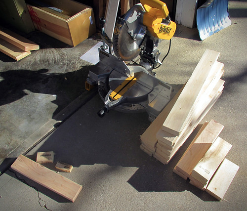
A friend of mine with a long trailer was recently doing a run to the local home store so I tagged along and picked up some lumber for the wing cart. It was a nice day out today, so I went out and cut the ten foot lengths of 2x4 to length. I'm using a design I found on Matronics, and I've since lost the attribution. All I have is an image I copied off the forums:
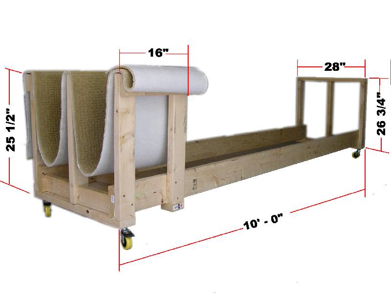 Click for a full-sized version. If that's your design, drop me a line and I'll give you credit here.
If you'd like to build a cart like this one, here's what you'll need to buy or find laying around:
Updated 2012.02.05 -- error in measurements
The 9" piece goes between the two vertical posts between the two wings at the wingtip end of the cart. The 11.75" pieces go perpendicular to and beneath the wings between the vertical posts at the wingtip end. Remember when comparing these dimensions to the diagram above that a 2x4 is actually 1.5" x 3.5" in cross section.
For now, I just have a bunch of cut pieces of lumber in a pile and four heavy-duty caster wheels.
I need to find a strip of carpet, but I'm still a long ways from needing the actual cart built anyway. This was just a get-ahead project for a sunny afternoon.
17 Jun 2012
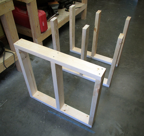
Today was a big day for the RV-10, as it was the first day of actual final assembly of the right wing. The first thing I started with was construction of the wing cradle, which I would need once the leading edge as attached to the main wing body. I had cut the lumber back in January but hadn't gotten around to actually assembling it until today. First up were the three vertical frames:
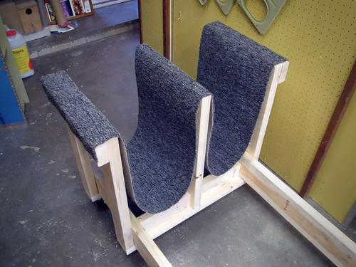
From there, I attached the long 2x6 boards and all of the rest of the little pieces. The last things to go on were the casters and the carpet. Here's a shot of the inboard end of the cradle fully assembled:
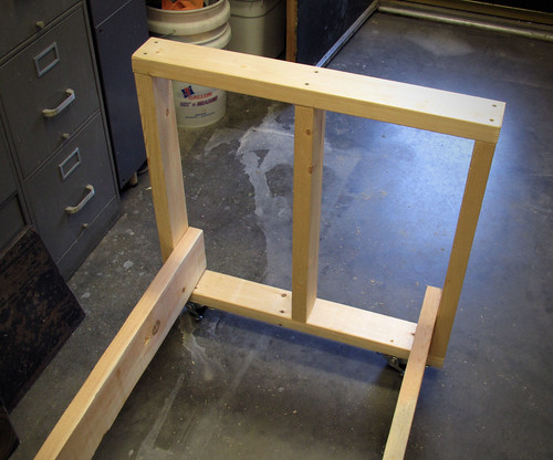
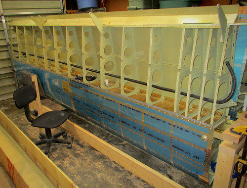
Not much to look at, but it's done. Here's a shot of the outboard end without the carpet so you can see where all the pieces go:

And finally, the outboard end with the carpet stapled on:
A few notes regarding the carpet: if you use my dimensions for the lumber, then the strip of carpet should be 16" x 8'. Find and mark the middle of the carpet, then staple it across the middle bar of the cradle. Next, take the ends of the carpet and staple them along the bottom edge of the outer-most face of the cradle. Put lots of staples across the tops of the side bars to keep the carpet held in place well and you're all set. These dimensions and attachment locations will keep the wing away from the wood and reasonably level. I tested mine by standing with one foot in each of the two carpet cradles. I weigh about 200 pounds (92kg) and the cradle had no problems with that at all. Cradle complete!
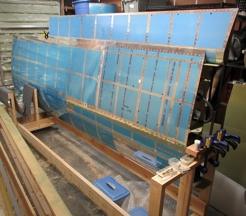
I put the cradle aside and brought the right wing body back out into the shop. I clamped it down to one of my 5' tables so that the outboard end stuck out into free space. With a helper sitting in a low chair, I got the leading edge lined up with the main spar and cleco'd into place.

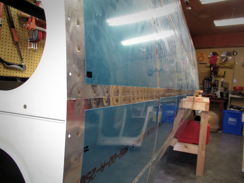
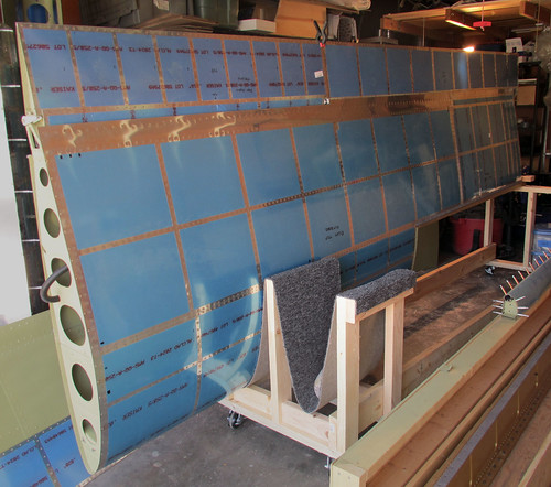
There's about 200 rivets holding the leading edge onto the main spar, and they went pretty quickly. A bunch of the rib rivets are blind rivets, and the entire bottom edge can be squeezed. Jeremy helped me bang out the rest of them in short order. The joint in the top skin between the main body and the leading edge is amazingly flush:
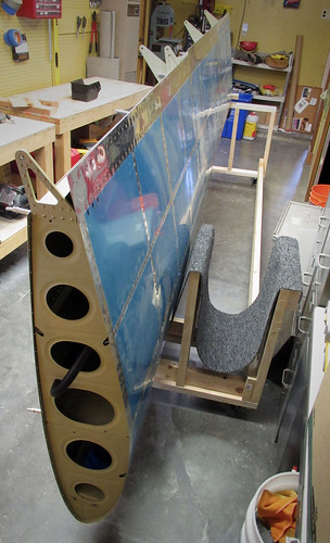
With that done, I moved the wing into the cradle which supported the wing beautifully.
I went ahead and cleco'd the bottom J stiffeners and skins in place because the wing makes a great place to store them until it is time to finish up the bottom skins.
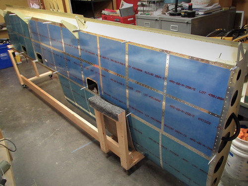
Exactly as planned, I was able to roll the cradle and wing out my shop door and into the garage without much trouble (the important part being that it isn't too wide for my narrow door). And now the shop is clear for whatever the next task is going to be. Options include
31 Aug 2012
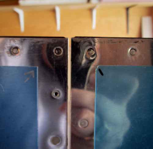
Before the flap can be attached to the right wing, I had to add three brass bushings to the flap hinge hangers coming out of the wing body. I found it easiest to press them into place by using a quick-clamp to apply presure uniformly. This got one side flush, then I added a small keyring to the flush side so that the bushing would push through a bit more and the install would be symmetric.
Once all three bushings were pressed into service, the flap dropped right into place with no clearance problems or alignment issues of any kind.
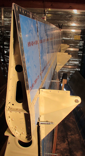
Holding the aileron in its trail position allowed me to check the alignment and clearance between the flap and aileron and these were perfect as well:
The flap actuation hardware will wait until after paining, so for now the flap is fully installed and ready for storage in the garage. Here's one more picture of the install, showing the bolted joints:
The only major component missing from the right wing now is the fuel tank.
22 July 2013
No shortage of motivation to work on the plane these days, now that the leaky fuel tank bottleneck is gone... The next step was to attach the right fuel tank to the mostly-complete right wing. This proved to be very difficult to do. I was not able to push the fuel tank all the way up to the point where the skin holes would align with the nutplates on the main spar. It turns out the problem was that the Z-brackets on the aft bulkhead of the fuel tank were slightly too wide. Part of this was due to the primer I added, but even after sanding all of that off they were too wide. I ended up having to take a dremel to the brackets to narrow them by a couple milimeters each. I'd recommend for future builders to shave these down a bit during the fabrication process rather than having to do it in situ. Anyway, once I got the brackets narrowed the tank slid relatively easily into place. I had to give it a few light taps with the falt of my palm on the nose of the ribs to get the last centimeter or so, but no great force was required. Here's the right tank in place:
Initially I had placed some clecos into the skin holes prior to lining up the bolt holes in the spar and this proved to be the wrong way to go. The skin holes are a bit more forgiving to misalignment, whereas the bolt holes need pretty careful alignment. I had to take out the clecos and give the tank a small yank inboard to line the bolt holes up. The friction between the Z-brackets and the spar was enough to hold the tank up without any fasteners. Once the first bracket's bolts were loosely in place, I went ahead and put the rest of the bolts in hand-tight. The last bracket to get bolts was the inboard one, where the bolts go in from the opposite side. This one was slightly misaligned and I had to push a couple tapered drift pins in from the top (through the spar holes and then into the nutplates) in order to push the Z-bracket into place, then place a bolt into the middle bolt hole. This allowed the removal of the drift pins and replacement with the proper bolts.
With all the bolts in place, I went through and added the proper torque to each and placed a stripe of torque seal lacquer to each. With all the bolts done, I went to work with an electric screwdriver (strongly recommended) and added the dozens of screws needed to attach the skin to the spar. I added a smidge of Boelube to each screw and bolt to help cut the threads in the nutplates. I'm really excited to have the completed fuel tank in place on the right wing!
16 Nov 2013
This morning I got the left wing's leading edge assembly attached to the main spar. I was able to get all of the rib rivets done solo.
Will came over in the afternoon and we made quick work of the 82 top-side skin rivets attaching the leading edge to the main wing spar.
17 Nov 2013
Did a quick stint today with the squeezer and finished off all of the rivets attaching the bottom skin of the leading edge on the left wing to the spar. This completes the attachment of the leading edge to the wing. Just 82 quick rivets; no photos.
19 Nov 2013
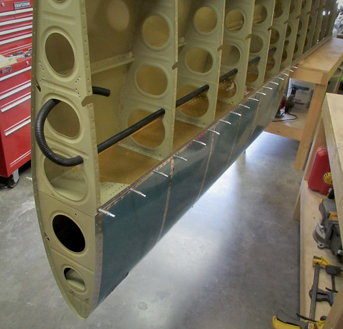
The left wing is just about ready to be moved into the garage and placed on the wing cart, an event which will need to occur prior to attaching the fuel tank. The one remaining small task will be to route the wiring harness from the inboard bay of the leading edge to the wing root. I had planned on running the wire through a series of snap bushings in the Z-attach brackets at the aft end of the fuel tank, but it turns out that the harness is too thick to fit through these holes. I don't want to enlarge these holes and risk weakening the support for the tank. Also, once I run wires through the fuel tank structure between the wing root and the leading edge, it pretty much means the tank is not removable without clipping the wiring harness.
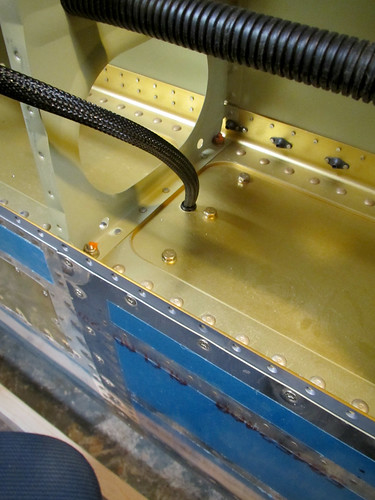
SO, instead I resolved to run the wire harness through the spar and into the main wiring conduit. To do this, I did have to widen the hole in the spar through which the stall warning switch wires would usually run in order to accomodate the three shielded pairs of 22AWG and larger snap bushing. The resulting hole was 1/2" in diameter. I consulted with my EAA technical advisor on this modification and he agreed it was acceptable, despite being in the main spar of the wing.
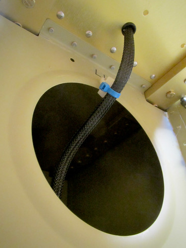
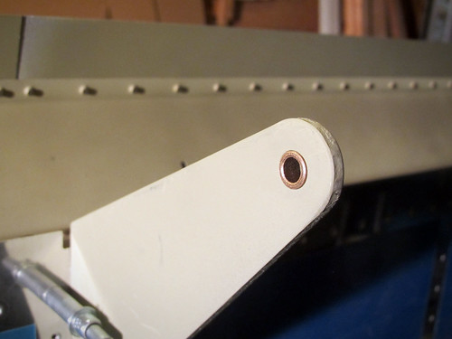
To negotiate the passage from the inboard bay of the leading edge to the narrow gap between the fuel tank and leading edge, I installed a plastic lightening hole wire passthrough with a single rivet onto the leading edge rib (the white thing in the image, above), and zip-tied the cable bundle into it. This will keep the harness from abrading on the edge of the lightening hole.
My only concern now is that the increased diameter of the spar hole and snap bushing may actually impinge on the outboard-most Z-attach bracket from the fuel tank. I haven't done the measurement yet but at most it will just be a few millimeters. I may have to grind an arc into the center of the outboard edge of the bracket or file a flat onto the snap bushing's outer edge or something.
17 Dec 2013
When Will was last here he helped me muscle the left wing from the shop into the garage and place it into the wing cradle. This freed me up to attach the fuel tank, but before I could proceed I needed to shave down the edges of the Z-attach brackets so that they'd fit gracefully between the main spar bars.
I took a dremel to the brackets just like last time and took off a few milimeters from each side. Once that was done, I just carried the tank into the garage, lifted it into place, and hand-tightened a few of the bolts into place. This was infinitely easier this time around, mostly because I had done the dremel work ahead of time, but also because I didn't try to align the tank with the screw holes before getting the bolts in place. I did all of the bolts first, then the screw holes were where they should have been without any fuss.
All of the bolts are now in place and torqued to 25 inch-pounds [pardon the lame units]. I started attaching the AN509-8R8 screws, of which there are a lot, each with a bit of Boelube, but my arm got tired pretty quick so that part's not done. Also, there's no good way for me to reach the top-side screws because the other wing is in the way, so those screws may have to wait until I next have one of the wings off the cradle.
One of the issues I was worried about with attaching the fuel tank turned out to be a total non-issue: there is no interference between the outboard Z-attach bracket and the leading edge wire bundle.
I was very careful not to pinch the cable harness when I was raising the fuel tank into place, and once I had all the bolts tightened down, I was still able to push and pull the wire harness through the snap bushing with essentially no resistance, so there is no problem with the expanded tooling hole, larger snap bushing, and larger wire bundle than outlined in the plans. Whew.
Time invested on this sub-assembly: 16 hours (14 by me)
Updates regarding wing assembly and attachment
23 Jan 2012A friend of mine with a long trailer was recently doing a run to the local home store so I tagged along and picked up some lumber for the wing cart. It was a nice day out today, so I went out and cut the ten foot lengths of 2x4 to length. I'm using a design I found on Matronics, and I've since lost the attribution. All I have is an image I copied off the forums:
Click for a full-sized version. If that's your design, drop me a line and I'll give you credit here.
If you'd like to build a cart like this one, here's what you'll need to buy or find laying around:
- 4 castering wheels
- 2 2x6x10'
- 3 2x4x10'
- 1 2x4x8'
- 1 16" x 8' length of carpet
| 10' | 28" | 28" | 28" | 24" | 9" |
|---|---|---|---|---|---|
| 10' | 28" | 24" | 24" | 24" | 16" |
| 10' | 24" | 24" | 23.75" | 23.75" | 16" |
| 8' | 23.75" | 10.25" | 10.25" | 10.25" | 10.25 |
The 9" piece goes between the two vertical posts between the two wings at the wingtip end of the cart. The 11.75" pieces go perpendicular to and beneath the wings between the vertical posts at the wingtip end. Remember when comparing these dimensions to the diagram above that a 2x4 is actually 1.5" x 3.5" in cross section.
For now, I just have a bunch of cut pieces of lumber in a pile and four heavy-duty caster wheels.
I need to find a strip of carpet, but I'm still a long ways from needing the actual cart built anyway. This was just a get-ahead project for a sunny afternoon.
17 Jun 2012
Today was a big day for the RV-10, as it was the first day of actual final assembly of the right wing. The first thing I started with was construction of the wing cradle, which I would need once the leading edge as attached to the main wing body. I had cut the lumber back in January but hadn't gotten around to actually assembling it until today. First up were the three vertical frames:
From there, I attached the long 2x6 boards and all of the rest of the little pieces. The last things to go on were the casters and the carpet. Here's a shot of the inboard end of the cradle fully assembled:
Not much to look at, but it's done. Here's a shot of the outboard end without the carpet so you can see where all the pieces go:
And finally, the outboard end with the carpet stapled on:
A few notes regarding the carpet: if you use my dimensions for the lumber, then the strip of carpet should be 16" x 8'. Find and mark the middle of the carpet, then staple it across the middle bar of the cradle. Next, take the ends of the carpet and staple them along the bottom edge of the outer-most face of the cradle. Put lots of staples across the tops of the side bars to keep the carpet held in place well and you're all set. These dimensions and attachment locations will keep the wing away from the wood and reasonably level. I tested mine by standing with one foot in each of the two carpet cradles. I weigh about 200 pounds (92kg) and the cradle had no problems with that at all. Cradle complete!
I put the cradle aside and brought the right wing body back out into the shop. I clamped it down to one of my 5' tables so that the outboard end stuck out into free space. With a helper sitting in a low chair, I got the leading edge lined up with the main spar and cleco'd into place.
There's about 200 rivets holding the leading edge onto the main spar, and they went pretty quickly. A bunch of the rib rivets are blind rivets, and the entire bottom edge can be squeezed. Jeremy helped me bang out the rest of them in short order. The joint in the top skin between the main body and the leading edge is amazingly flush:
With that done, I moved the wing into the cradle which supported the wing beautifully.
I went ahead and cleco'd the bottom J stiffeners and skins in place because the wing makes a great place to store them until it is time to finish up the bottom skins.
Exactly as planned, I was able to roll the cradle and wing out my shop door and into the garage without much trouble (the important part being that it isn't too wide for my narrow door). And now the shop is clear for whatever the next task is going to be. Options include
- Right wing bottom skin
- Finish left fuel tank
- Start right fuel tank
- Do an aileron or flap
31 Aug 2012
Before the flap can be attached to the right wing, I had to add three brass bushings to the flap hinge hangers coming out of the wing body. I found it easiest to press them into place by using a quick-clamp to apply presure uniformly. This got one side flush, then I added a small keyring to the flush side so that the bushing would push through a bit more and the install would be symmetric.
Once all three bushings were pressed into service, the flap dropped right into place with no clearance problems or alignment issues of any kind.
Holding the aileron in its trail position allowed me to check the alignment and clearance between the flap and aileron and these were perfect as well:
The flap actuation hardware will wait until after paining, so for now the flap is fully installed and ready for storage in the garage. Here's one more picture of the install, showing the bolted joints:
The only major component missing from the right wing now is the fuel tank.
22 July 2013
No shortage of motivation to work on the plane these days, now that the leaky fuel tank bottleneck is gone... The next step was to attach the right fuel tank to the mostly-complete right wing. This proved to be very difficult to do. I was not able to push the fuel tank all the way up to the point where the skin holes would align with the nutplates on the main spar. It turns out the problem was that the Z-brackets on the aft bulkhead of the fuel tank were slightly too wide. Part of this was due to the primer I added, but even after sanding all of that off they were too wide. I ended up having to take a dremel to the brackets to narrow them by a couple milimeters each. I'd recommend for future builders to shave these down a bit during the fabrication process rather than having to do it in situ. Anyway, once I got the brackets narrowed the tank slid relatively easily into place. I had to give it a few light taps with the falt of my palm on the nose of the ribs to get the last centimeter or so, but no great force was required. Here's the right tank in place:
Initially I had placed some clecos into the skin holes prior to lining up the bolt holes in the spar and this proved to be the wrong way to go. The skin holes are a bit more forgiving to misalignment, whereas the bolt holes need pretty careful alignment. I had to take out the clecos and give the tank a small yank inboard to line the bolt holes up. The friction between the Z-brackets and the spar was enough to hold the tank up without any fasteners. Once the first bracket's bolts were loosely in place, I went ahead and put the rest of the bolts in hand-tight. The last bracket to get bolts was the inboard one, where the bolts go in from the opposite side. This one was slightly misaligned and I had to push a couple tapered drift pins in from the top (through the spar holes and then into the nutplates) in order to push the Z-bracket into place, then place a bolt into the middle bolt hole. This allowed the removal of the drift pins and replacement with the proper bolts.
With all the bolts in place, I went through and added the proper torque to each and placed a stripe of torque seal lacquer to each. With all the bolts done, I went to work with an electric screwdriver (strongly recommended) and added the dozens of screws needed to attach the skin to the spar. I added a smidge of Boelube to each screw and bolt to help cut the threads in the nutplates. I'm really excited to have the completed fuel tank in place on the right wing!
16 Nov 2013
This morning I got the left wing's leading edge assembly attached to the main spar. I was able to get all of the rib rivets done solo.
Will came over in the afternoon and we made quick work of the 82 top-side skin rivets attaching the leading edge to the main wing spar.
17 Nov 2013
Did a quick stint today with the squeezer and finished off all of the rivets attaching the bottom skin of the leading edge on the left wing to the spar. This completes the attachment of the leading edge to the wing. Just 82 quick rivets; no photos.
19 Nov 2013
The left wing is just about ready to be moved into the garage and placed on the wing cart, an event which will need to occur prior to attaching the fuel tank. The one remaining small task will be to route the wiring harness from the inboard bay of the leading edge to the wing root. I had planned on running the wire through a series of snap bushings in the Z-attach brackets at the aft end of the fuel tank, but it turns out that the harness is too thick to fit through these holes. I don't want to enlarge these holes and risk weakening the support for the tank. Also, once I run wires through the fuel tank structure between the wing root and the leading edge, it pretty much means the tank is not removable without clipping the wiring harness.
SO, instead I resolved to run the wire harness through the spar and into the main wiring conduit. To do this, I did have to widen the hole in the spar through which the stall warning switch wires would usually run in order to accomodate the three shielded pairs of 22AWG and larger snap bushing. The resulting hole was 1/2" in diameter. I consulted with my EAA technical advisor on this modification and he agreed it was acceptable, despite being in the main spar of the wing.
To negotiate the passage from the inboard bay of the leading edge to the narrow gap between the fuel tank and leading edge, I installed a plastic lightening hole wire passthrough with a single rivet onto the leading edge rib (the white thing in the image, above), and zip-tied the cable bundle into it. This will keep the harness from abrading on the edge of the lightening hole.
My only concern now is that the increased diameter of the spar hole and snap bushing may actually impinge on the outboard-most Z-attach bracket from the fuel tank. I haven't done the measurement yet but at most it will just be a few millimeters. I may have to grind an arc into the center of the outboard edge of the bracket or file a flat onto the snap bushing's outer edge or something.
17 Dec 2013
When Will was last here he helped me muscle the left wing from the shop into the garage and place it into the wing cradle. This freed me up to attach the fuel tank, but before I could proceed I needed to shave down the edges of the Z-attach brackets so that they'd fit gracefully between the main spar bars.
I took a dremel to the brackets just like last time and took off a few milimeters from each side. Once that was done, I just carried the tank into the garage, lifted it into place, and hand-tightened a few of the bolts into place. This was infinitely easier this time around, mostly because I had done the dremel work ahead of time, but also because I didn't try to align the tank with the screw holes before getting the bolts in place. I did all of the bolts first, then the screw holes were where they should have been without any fuss.
All of the bolts are now in place and torqued to 25 inch-pounds [pardon the lame units]. I started attaching the AN509-8R8 screws, of which there are a lot, each with a bit of Boelube, but my arm got tired pretty quick so that part's not done. Also, there's no good way for me to reach the top-side screws because the other wing is in the way, so those screws may have to wait until I next have one of the wings off the cradle.
One of the issues I was worried about with attaching the fuel tank turned out to be a total non-issue: there is no interference between the outboard Z-attach bracket and the leading edge wire bundle.
I was very careful not to pinch the cable harness when I was raising the fuel tank into place, and once I had all the bolts tightened down, I was still able to push and pull the wire harness through the snap bushing with essentially no resistance, so there is no problem with the expanded tooling hole, larger snap bushing, and larger wire bundle than outlined in the plans. Whew.