| Workshop | Empennage | Wings | Fuselage | Contact |
Running Wires to the Vertical Stabilizer Fairing
The stock RV-10 kit does not include any provisions for running wires to the
vertical stabilizer fairing. However, this fairing makes an excellent place
to mount a forward-looking camera, or even a small antenna. I had no plans
to install either of these as I built, but I didn't want to rule out the option
later. Thus, I ran a bundle of wires through the vertical stabilizer during
construction along with an empty conduit to support future upgrades. Both of
these can be done with minimal expense, effort, or added weight.
I settled on the AMP/Tyco 206705-3 9-pin circular plastic connector. They cost $3.50 each and I needed two (one for inside the VS fairing and one for the bottom of the lower nose rib). The crimp-on sockets for each wire cost $0.54 each (I got the gold-coated ones; no need to skimp on wiring quality as far as I'm concerned), and I need about 20. In order to crimp the sockets, an expensive crimping tool is required ($138), but it can be used for all AMP/Tyco CPC contacts throughout the plane. I also picked up a $12.52 pin extractor tool which came in handy on numerous occasions. For each of the two connectors, I picked up a heat shrink sealing boot ($8.24) and a plastic sealing cap ($3.09) as well.
Once the VS is buttoned up, none of the wires will be visible so I didn't worry about wire color. I purchased fifty feet of white 18awg tefzel wireand this was plenty. Around the wire went a 3/8" braided nylon sheath. I also ran a piece of Van's 3/4" black plastic conduit in parallel to the wire bundle (to accomodate an antenna cable or additional wiring in the future if necessary). Both the wires and the conduit ended up being a bit over three feet in length.
At the bottom end of the VS, the conduit and CPC will be accessible through lightening holes in the lower nose rib. To avoid having to punch large holes in the web of the rib, I added a doubler plate to the entire rib which covered the lightening holes. As this doubler does not have to support much in the way of structural loads, I made it out of the thinnest spare aluminum sheet that Van's shipped with the empennage kit. The upper rib has no lightening holes and thus required a pair of 3/4" holes to be drilled in it. Because this was a significant size relative to the width of the upper rib, I added a stiff doubler to this area made of the thickest spare sheet aluminum that shipped with the empennage kit.
When the conduit and wire bundle pass through the middle nose rib, I wanted to ensure that they wouldn't rub on the edges of the lightening holes and possible abraid the cables/conduit. I found a company called Panduit that makes an ideal line of products for exactly this purpose. Two are required for the VS wiring, one for the wire bundle and one for the conduit. I bought mine from mouser.com.
And here it is again after drilling out the two 3/4" holes (with a unibit) and clecoing in the connector:
Finally, here it is riveted in place after all the parts had been primed:
Here is the upper nose rib doubler with all the holes drilled, along with the matching holes in the nose rib itself:
And here it is again after priming and riveting:
Note that I mistakenly riveted the doubler to the top side of the rib rather than the bottom;I had intended the doubler to be out of sight and for the machine heads of the rivets to be on the fairing side of the rib. Not a big deal, but remember when you fabricate yours that the flanges on the top rib face up unlike on the middle and bottom ribs.
The middle rib modifications are quite simple; two extra 1/8" holes and a rivet in each, along with the Panduit lightening hole wire tie mounts:
I did all of the upper rib wire and conduit attachment first. The conduit I stuck through the hole about 3/8" and then used black RTV silicone to seal the interface between metal and conduit. I only applied on the RTV on the lower side of the upper rib so that it wouldn't be visible once the skin was in place. For the wire bundle, I crimped sockets onto each of the nine wires, plugged them into the connector, threaded the other end of the wire through the braided sheath, then threaded the sheath through the heat shrink boot. Once all of the wires were run, I put a wire tie around the sheath then screwed the boot into place. I used a heat gun to shrink the boot; it does a great job of strain relief and holding the sheath in place.
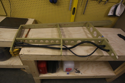
The tricky part about running the actual wires and conduit is that they have to be run a bit long because of how the riveting is done on the middle nose rib flanges. The bottom nose rib has to be removed to rivet the skin to the middle nose rib, and then the bottom nose rib is replaced and riveted to the skin itself This means that the wires and conduit have to be long enough to allow the lower rib to be detached and hang far enough out that you can fit your arm into the nose rib space and buck those rivets. For the conduit this is not a major issue; the slack in it can always be pulled out after the skin is all riveted on. The slack in the wire bundle, unfortunately, is staying. However, if you keep it as short as possible, and be careful about where the slack bends when the lower rib is put back in place, you can ensure that the bend in the wire bundle goes foreward, causing the bundle to rub against the smooth foreward inner surface of the skin rather than the possibly abrasive lightening holes of the forward spar. Here is a picture of the over-length wire bundle and conduit in place before I started riveting the skin in place:
Once the skin was riveted on, the conduit slack was pulled through, and I added another fillet of black RTV by putting a blob of it on my finger and reaching up through the foreward-most (smallest) lightening hole in the lower rib and applying the fillet with my finger. Probably not a perfect fillet in there, but not visible and sufficient to keep the conduit from vibrating against the metal edge of the doubler.
With that, the VS wiring is complete. With the addition of a removable VS fairing, accessories can now be added to the fairing and wired securely without having to open up the VS.
Parts Selection
The first choice to make was how many wires and what gauge? The most likely electrical gadget for me to install in the VS fairing would be a camera, which would require four wires (power, ground, signal, signal ground). Just to be safe, I doubled that and used eight as the minimum number of wires I would run. The most power-intensive thing I could think of possibly wanting to run to the VS fairing would be a beacon light of some kind. I figured that 18awg wire would be more that sufficient for such an installation. Finally, I selected a bulkhead connector that would support at least eight 18awg wires with environmental seals, quick disconnects, and reasonably light weight.I settled on the AMP/Tyco 206705-3 9-pin circular plastic connector. They cost $3.50 each and I needed two (one for inside the VS fairing and one for the bottom of the lower nose rib). The crimp-on sockets for each wire cost $0.54 each (I got the gold-coated ones; no need to skimp on wiring quality as far as I'm concerned), and I need about 20. In order to crimp the sockets, an expensive crimping tool is required ($138), but it can be used for all AMP/Tyco CPC contacts throughout the plane. I also picked up a $12.52 pin extractor tool which came in handy on numerous occasions. For each of the two connectors, I picked up a heat shrink sealing boot ($8.24) and a plastic sealing cap ($3.09) as well.
Once the VS is buttoned up, none of the wires will be visible so I didn't worry about wire color. I purchased fifty feet of white 18awg tefzel wireand this was plenty. Around the wire went a 3/8" braided nylon sheath. I also ran a piece of Van's 3/4" black plastic conduit in parallel to the wire bundle (to accomodate an antenna cable or additional wiring in the future if necessary). Both the wires and the conduit ended up being a bit over three feet in length.
At the bottom end of the VS, the conduit and CPC will be accessible through lightening holes in the lower nose rib. To avoid having to punch large holes in the web of the rib, I added a doubler plate to the entire rib which covered the lightening holes. As this doubler does not have to support much in the way of structural loads, I made it out of the thinnest spare aluminum sheet that Van's shipped with the empennage kit. The upper rib has no lightening holes and thus required a pair of 3/4" holes to be drilled in it. Because this was a significant size relative to the width of the upper rib, I added a stiff doubler to this area made of the thickest spare sheet aluminum that shipped with the empennage kit.
When the conduit and wire bundle pass through the middle nose rib, I wanted to ensure that they wouldn't rub on the edges of the lightening holes and possible abraid the cables/conduit. I found a company called Panduit that makes an ideal line of products for exactly this purpose. Two are required for the VS wiring, one for the wire bundle and one for the conduit. I bought mine from mouser.com.
Assembly
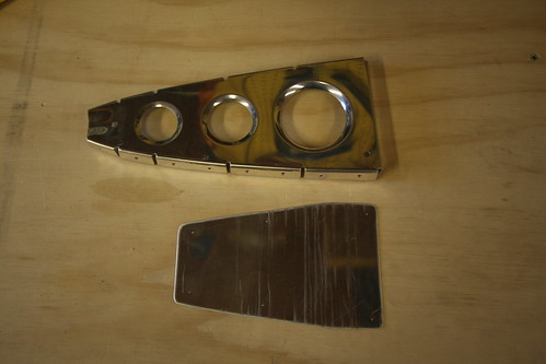
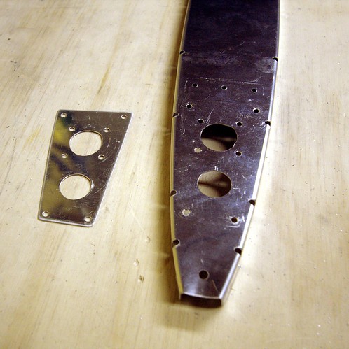
The first task was to fabricate the two custom doubler plates. Precision shaping was not required here, so I just sketched the outline of the two parts onto the sheet aluminum and used a bandsaw to cut out the necessary pieces. I smoothed out the edges with a scotchbrite wheel. Here is the lower doubler:
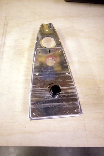
And here it is again after drilling out the two 3/4" holes (with a unibit) and clecoing in the connector:
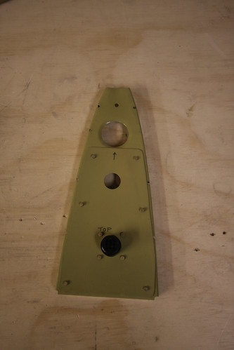
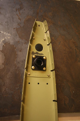
Finally, here it is riveted in place after all the parts had been primed:
Here is the upper nose rib doubler with all the holes drilled, along with the matching holes in the nose rib itself:
And here it is again after priming and riveting:
Note that I mistakenly riveted the doubler to the top side of the rib rather than the bottom;I had intended the doubler to be out of sight and for the machine heads of the rivets to be on the fairing side of the rib. Not a big deal, but remember when you fabricate yours that the flanges on the top rib face up unlike on the middle and bottom ribs.
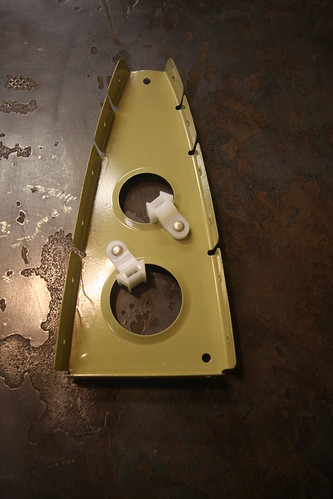
The middle rib modifications are quite simple; two extra 1/8" holes and a rivet in each, along with the Panduit lightening hole wire tie mounts:
I did all of the upper rib wire and conduit attachment first. The conduit I stuck through the hole about 3/8" and then used black RTV silicone to seal the interface between metal and conduit. I only applied on the RTV on the lower side of the upper rib so that it wouldn't be visible once the skin was in place. For the wire bundle, I crimped sockets onto each of the nine wires, plugged them into the connector, threaded the other end of the wire through the braided sheath, then threaded the sheath through the heat shrink boot. Once all of the wires were run, I put a wire tie around the sheath then screwed the boot into place. I used a heat gun to shrink the boot; it does a great job of strain relief and holding the sheath in place.
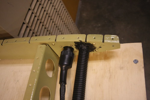
The tricky part about running the actual wires and conduit is that they have to be run a bit long because of how the riveting is done on the middle nose rib flanges. The bottom nose rib has to be removed to rivet the skin to the middle nose rib, and then the bottom nose rib is replaced and riveted to the skin itself This means that the wires and conduit have to be long enough to allow the lower rib to be detached and hang far enough out that you can fit your arm into the nose rib space and buck those rivets. For the conduit this is not a major issue; the slack in it can always be pulled out after the skin is all riveted on. The slack in the wire bundle, unfortunately, is staying. However, if you keep it as short as possible, and be careful about where the slack bends when the lower rib is put back in place, you can ensure that the bend in the wire bundle goes foreward, causing the bundle to rub against the smooth foreward inner surface of the skin rather than the possibly abrasive lightening holes of the forward spar. Here is a picture of the over-length wire bundle and conduit in place before I started riveting the skin in place:
Once the skin was riveted on, the conduit slack was pulled through, and I added another fillet of black RTV by putting a blob of it on my finger and reaching up through the foreward-most (smallest) lightening hole in the lower rib and applying the fillet with my finger. Probably not a perfect fillet in there, but not visible and sufficient to keep the conduit from vibrating against the metal edge of the doubler.
With that, the VS wiring is complete. With the addition of a removable VS fairing, accessories can now be added to the fairing and wired securely without having to open up the VS.