| Workshop | Empennage | Wings | Fuselage | Contact |
Vertical Stabilizer Construction
Current status: Complete except for fairing.
Time invested on this sub-assembly: 49 hours (42 by me)
The only customization I'm adding to the V.S. is allowing for the possible future addition of a forward-facing camera in the fairing. To achieve this, I'll put a panel-mount CPC into the upper foreward rib and run a cable down to the bottom of the V.S., where another panel-mount CPC will be placed for eventual connection to a cable coming from the fuselage. For the time being, I will not be buying a camera. However, to facilitate putting one into the fairing later, I am modifying the fairing to be removable (i.e. nutplates instead of rivets).
(First part of this entry concerns the tool box practice kit only)
After finishing the box I drove down to Santa Fe for a flight lesson, and what I thought might be my first solo. But it suddenly got so windy that we decided not to fly at all and just walked around the ramp at SAF looking at all the planes. I did manage to put in one whole hour of actual work on the plane—my first actual hour of construction work!
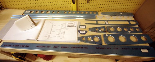
I grabbed all of the vertical stabilizer parts off of the shelf I had reserved for this subassembly, and was pleased to find that everything called out in the plans was there where it should have been. Score one for thorough inventory last night.
A lot of builders have commented on consternation regarding the first step, the long bandsaw cuts on the rear spar caps (VS-1014). I had some concern as well, but mostly because my bandsaw doesn't list aluminum as one of the things it would cut. During the toolbox construction, I tested this by cutting the aluminum hinge to length on the bandsaw and it went through it like butter... so I guessed I was probably good to go on the spar caps. The cuts took a long time but came out looking great.
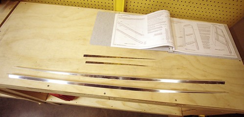
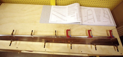
I did all of the deburring of these two parts on the scotchbrite wheel which went very quickly. The only problem was the enormous amount of warp! It made it hard to mark a straight line (because I had to have the thing clamped in four places to the workbench in order to keep it straight, and the clamps got in the way of the straightedge). It also makes the beginning of step 2 interesting, where you are supposed to nest the spar caps inside the flange of the rear spar. It took 11 clamps before I felt like the spar caps were sitting where they should be in the spar.
That's it for my first day of real construction work. Just one hour.
10 Oct 2009
My 4-day weekend of plane building continues. Spent about 8 hours today on the vertical stabilizer. First up was finishing §6.2.2 which I had started last night. With all the clamps in place, the bendy spar caps weren't an issue. It did require the use of a 1/8" drill bit, which was not included in my tool kit from planetools.com. I thought about just using a #30, which is close, but saw that the instructions have me coming back through with a #30 later for final drilling and figured there's probably a reason. So I ran to the hardware store and picked up a new bit (the only 1/8" bit I had was a wood-cutting bit).
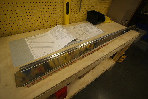
Step three took a ton of time, because for whatever reason I decided to put a cleco in every hole as I went, so when I had to remove the spar caps to deburr the holes, I had to take out about 100 clecos. And then I put them all back in again like a doofus. Look at this ridiculous thing:
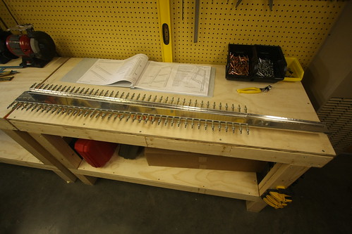
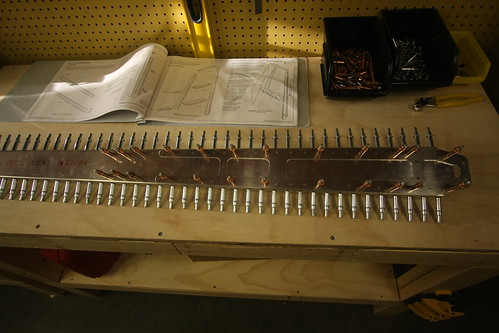
The spar doubler cleaned up nicely on the scotchbrite wheel, though I couldn't do the interior surfaces. Those I worked with a file and broke the edges with a pencil deburring tool. As you can see, this time I was a bit more frugal with the clecos (partially because the spar doubler was considerably less bent than the caps).
At this point I removed everything except the caps and deburred all holes. I neglected to mark which hinge half was which before taking them off and had to reassemble them and check before continuing. Small oops, but no biggie. With the hinge parts finished and not needed for the rest of assembly, I left them off along with the VS-1017 hinge doubler for the remainder of today's work. This allowed the vertical stabilizer to lay flat on the aft side of its rear spar, making working on the skeleton and skins easier. The next step was to machine countersink the spar doubler and this was where I made my first significant oops. I got so involved with figuring out where to set the countersink cage for proper depth that I forgot that I only wanted to countersink the holes beneath the upper attach bolt holes. I countersunk eight of the wrong holes before I realized my mistake. Hopefully I can just use AN426 flush rivets here instead of the AN470 called out in the plans. I'll fire off an email to Van's and confirm this. Otherwise, I'll have to order and refabricate a new spar doubler and that will be a pain. For now, this mistake does not prevent me from continuing with the fabrication of the vertical stabilizer. Not a great way to finish my first page of the plans, but that's it! Page §6.2 complete (sort of)!
I deburred the rest of the skeleton parts on the scotchbrite wheel and used the pencil tool on the lightening holes. Worked great. Paid special attention to the nose rib points, which I ground down about 3/16" so as not to dimple the skin leading edge when I fold it over the skeleton. Onec that was done, I went ahead and assembled the skeleton with the rear spar clamped to a leg of my workbench:
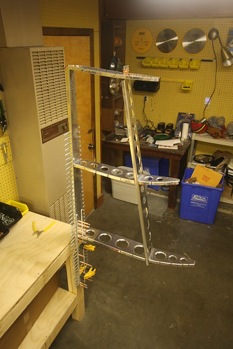
It was really wobbly. It was really disconcerting how little structural stability this skeleton has with no skin on it. Whereas the rear spar is solid as a rock with those caps and doubler in there, the rest of the parts are just wibbly and I feel like it was going to fold under its own weight. Yikes. Anyway, I thought it would be cool to work on the assembly in its natural upright position, but this came to a rapid end as I needed to final drill those holes on the top rib where it connects to the front spar, and with it clamped to the bench like this, those holes were about six feet off the floor! It made for a cool picture, anyway.
Back on the table, I got the skeleton final drilling out of the way and prepared to put the skin on! First, I had to remove the vinyl from the inside surface. This proved to be harder than I thought it would be. Removing the vinyl from the other parts had been reasonably straightforward. Here I ended up having to wrap the vinyl around a broom handle and rolling that up to pull the coating off. It seemed a lot more sticky than the other parts. Took about 10 minutes just to get the vinyl off that one part. Then, another short bit of instructions that takes forever. "Clecko the skin to the skeleton" translated into about two hours of work. I'm not sure why I had such a hard time with this, but everything I was trying was not working. The hardest part was getting the holes to line up on the middle nose rib. In the end, what worked the best was doing the clecos on one side for everything but the middle nose rib, then turning the assembly over.
Next, I helt a cleco in the hole for the forward-most hole in the skin for the nose rib, then with my other arm I reached under the skin and wiggled the rib back and forth until I got the cleco to drop. It was a giant pain, but it was only required for the five or six rivets on the one side of that nose rib. Once that was done, everything else went into place pretty easily. I finished up with clecoing the skin to the skeleton and called it a night. The result looked something like this:
It's nice to have something that vaguely resembles a plane part on the bench! Also, it was pleasing to note that with the skin on, the stabilizer was rock solid, not the miserable flimsy thing the skeleton had been. First thing tomorrow will be §6.3.4: match-drilling each and every hole in the skin. Unfortunately, after that step, the whole assembly comes apart again for awhile.
11 Oct 2009
Most of the six hours of work that got done today involved things that don't have much visual impact on the vertical stabilizer at all. A lot of dimpling, deburring, and match-drilling parts that were already together. Probably the most visually striking thing that happened was when I removed some strips of vinyl from the front of the VS skin. Bob came by to check out the project so I put him to work helping me get the vinyl strips off.
Aside from the vinyl modification, I got all of the skin holes match drilled and deburred. I also deburred all of the skin/skeleton interface holes on the skeleton. I then started the dimpling. Got all of the skeleton holes dimpled, but gave up on trying to dimple the skin by myself since Bob said he'd help over lunch tomorrow and it'll be a lot easier with two people. The skeleton dimpling required all three of my available dimpling techniques! Most of it was done on the DRDT-2 dimpler (which I love), but a few of the corner holes and holes in the narrow pieces wouldn't work there, so I broke out the pneumatic squeezer and took care of the rest—except for the forward two holes on the top rib, for which even the squeezer wouldn't do. For these, I had to use the pop rivet tool and the nail/dimple die combo. Worked like a champ.
Also took care of countersinking the rear spar/skin interface holes where called out in §6.3.8. With the exception of the skin dimples, the next step is to disassemble the rear spar bits. This will be the last time the spar is together before the parts are primed, so I am likely to hold on doing §6.3.9 until I figure out a few of the customizations I'm going to be adding to this subassembly. In particular, I need to figure out where and how to mount the braided copper grounding straps that will run between the VS and the rudder.
12 Oct 2009
The last day of my four day RV-10 superweekend.
Spent the morning finishing minor tasks like preparing the rudder stops and match-drilling the hinges, etc. When Bob showed up on his lunchbreak, we made quick work of the skin dimpling. The very front hole in the middle rib was not reachable with the DRDT-2 so I had to pop-dimple that one. Otherwise we knocked it out in about 10 minutes and went out for Chinese food.
Spent the rest of the day working on some custom parts for my electrical run to the vertical stabilizer fairing. I know I want to mount a camera up there someday, and I have vague notions of someday flying internationally with this thing which means I may need an HF antenna—the top of the tail is a logical place for one end of a longwire antenna on a plane. So I'm running a harness of cables from inside the VS fairing to the base of the VS with circular plastic connectors on each end to facilitate hooking up accessories in the future without having to do a tricky cable run. I also am going to run an empty conduit up to the top in case I want to run an antenna cable but don't want to have lossy connectors in line.
To pull this off, I need doublers at both the top and bottom nose ribs and some way to keep the conduit and cables off the lightening hole edges on the middle nose rib.
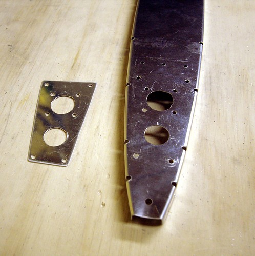
Here is the doubler plate I whipped up for the bottom nose rib. I know it's unnecessarily huge... but whatever it's light. I drilled out holes for the connector and conduit, and rivet holes to attach it to the nose rib and ended up something like this:
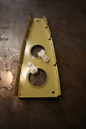
For the middle nose rib I found the perfect product—a wire tie bracket made especially for riveting onto lightening holes. How perfect? I just had to drill two small rivet holes in the middle nose rib.
For the top rib I had to make a much more compact doubler since the rib itself is so small. I had concerns about so many holes in such a small piece, but the technical support people at Van's said they didn't forsee any problem with this.
That's about it for today. Only about five hours of actual work. At this point, I am at §6.4.5 which states, simply, "prime the parts." This is going to take some infrastructure preparation so it may be awhile before significant progress occurs on the vertical stab.
29 Oct 2009
A bunch of random things have occurred in the last week. After reading up on other builders websites, I determined that I wouldn't be making the bend in the trailing edge of the rudder at all. I'll be using the angle iron backrivet technique and tank sealant to ensure a good bond at the trailing edge.
Making this decision cleared me to finish up the rudder skins. I removed the vinyl coating from the rivet lines and Bob assisted with the dimpling of all the holes. The next step on the skins will be to scuff the inner surface, clean it, and then prime it.
I spent a lot of time thinking about how to do bond straps between the rudder and vertical stab. I was unable to find appropriate ring terminals, bolts, washers, and nuts in aluminum... so I've decided to use passivated cadmium-plated steel hardware instead and hope for the best. I ordered some candidate pieces from Aircraft Spruce and they look like they might work. I also ordered hardware for making the vertical stabilizer and lower rudder fairings removable via nutplates. Unfortunately I based my parts decisions here on another builder's website who had a typo in their part numbers! I ordered thirty K1000-6 nutplates instead of K1000-06 nutplates without checking the bolt size vs. nutplate size. That's a $50 oops! Reordered the correct nutplates from Van's. They'll be here long before I'm ready for them. If anyone needs any of the huge K1000-6 nutplates... let me know.
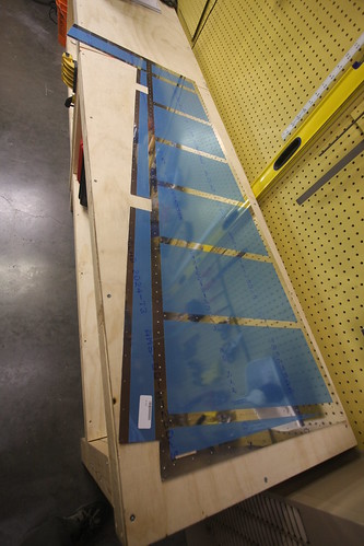
The other major accomplishment of this week was building the dunk tank for doing alumiprep and alodine chemistry on the long thin parts of the aircraft. I didn't want to have to build more than one of these, so I made it really long to accomodate the longest pieces of the airplane. Right now, the longest parts I know of are the horizontal stabilizer spars, which come in at about 11'6" each. I bought three twelve foot 2x4s and made a simple double-trough frame out of them. I used the plywood from the empennage delivery crate for the bottom of the troughs, and a four foot spare piece of 2x4 from the workbench assembly for the end caps. Drilled drain holes in one end and fashioned a couple of 2x4 blocks to allow for length customization, saving on chemical volume when working on parts shorter than the horizontal stabilizer spars.
Above is a picture of the finished dunk tank with the length blocks set at about six feet, just longer than the longest parts in both the rudder and vertical stabilizer. I then lined the active side of the tank with 4 mil plastic sheet and poked it down through the drain holes. I used a staple gun to temporarily keep the sheet in place. The dunk tank is ready to go! More pictures here.
The last thing I did was to rig up hooks and line for allowing the parts to air dry after the alumiprep and alodine washes are complete. Currently all of the parts for both the vertical stabilizer and rudder and hanging in the shop. The only thing I'm missing before I proceed with the chemistry is buckets to reclaim the used water and chemicals. Should be able to pick those up at the local hardware store. Then, it'll be time for SCIENCE!
31 Oct 2009
Got three sealable five-gallon buckets this morning, one for alodine, one for alumiprep, and one for distilled water. The Alodine comes by the gallon and gets mixed 1:2 with water, for a total of three gallons of solution. The Alumiprep also comes by the gallon and gets mixed 1:3 with water, for four gallons of solution. I pre-mixed these and labeled their respective buckets.
With the adjustable blocks in my dunk tank set at just over five feet (the length of the rudder spar), and each trough being six inches wide, three gallons was enough for an almost two inch deep pool of Alodine. I only used about three gallons of the Alumiprep as well.
The process of immersing the parts in each bath and then drying went surprisingly quickly. I was able to prep and alodine all of the parts for both the vertical stabilizer and rudder in about two hours including setup and cleanup. Also, this was my first time figuring out how everything would work, so I took a lot longer on some steps than I will require when I do this again for the horizontal stabilizer.
All of the parts now have that great golden finish to them and are ready for priming.
2 Nov 2009
Quite a bit has happened over the past two days. For starters, I primed all of the rudder and vertical stabilizer parts. Riveting together of the vertical stabilizer skeleton has also been started. Here's me about to stat priming all of the non-skin parts.

And here's all of the parts, including the skins, drying after being primed with Akzo 2-part epoxy primer.
Once everything had dried for a few hours, I started in on the vertical stabilizer riveting. The very first rivet in the plane was between the lower rudder hinge bracket and the rudder stop. Unfortunately, I was excited about doing some riveting and failed to follow the instructions; I did all six of these rivets with the second hinge bracket in there too. Not right. Had to drill them all out and start over. Whoops! Once I got past that little snafu, I riveted together the VS rear spar, spar caps, doublers, and rudder hinges. This took a grand total of 75 rivets, almost all of which could be done with the squeezer. The universal rivets that attach the hinges closest to the corner of the hinge have to be done with the rivet gun and bucking bar, and I cleated one of these. Had to drill it out and replace it.
I didn't put on the upper half of the upper hinge bracket, or the upper middle rivet on the upper hinge doubler because I want to replace this rivet with a mounting bolt for a bond strap to run between the VS and the rudder. I'm still having problems figuring out what the right bolt/nut/ring terminal combination is for this, so that bit is on hold. Below is a photo of the upper hinge area showing the unfinished rivets. I also have an AN3-4 bolt there with a castle nut, ring terminal, and some washers there for sacle. The problem with the AN series bolts is that the threaded section is just too short to have a permanently-attached bolt/nut combo and then a removable ring terminal/castle nut combo on top of that. I'm looking for a slightly longer bolt with a shorter grip, and it has to be passivated. So far, no joy.
Tabling the rear VS spar for now, I moved on to the forward VS spar, which needs very little treatment. Just 10 rivets for the doubler—four flush and six universal. I used the squeezer on the universals which was a breeze, and then used my new back riveting plate on the flush which was also quite straightforward. Nina was around while I was doing this, so I showed her how to use both the squeezer and the rivet gun. She did four of the rivets on this part and they all look great.
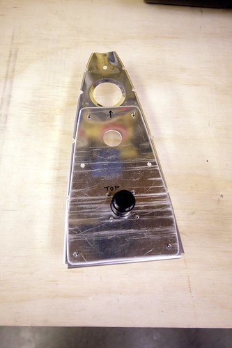
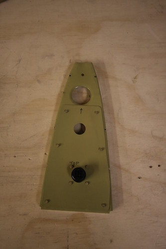
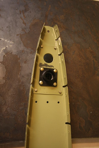
From there, it was time for the customizations to the forward ribs for the wiring and conduit runs. First up was the lower rib, which got a custom doubler plate and the circular plastic connector riveted into the doubler:
Then the top rib doubler and CPC. Here I made a small mistake; I meant to put the doubler on the bottom of the rib, but forgot that this rib gets installed flanges-up. By the time I had noticed, the doubler was already fully riveted into the web. Not a big problem; but you can still read my sharpee'd "bottom" notation on the top of the doubler. No big deal, bit I need to be more careful. Too many mistakes.
Last up was the forward middle rib, which just got two wire tie anchors riveted into the two lightening holes. One will secure the conduit, the other the wire bundle.
I'll probably go ahead and rivet up the rest of the VS skeleton soon since I can still do the grounding post modification after the skeleton is assembled. Riveting on the skin will have to wait for the bolt issue to be resolved, however.
3 Nov 2009
Riveted together the skeleton pieces (except for the lower inspar and forward ribs, as per the instructions). This required only 11 rivets, eight of which could be squeezed, so it went very quickly. The rest of the session was spent routing cables and conduit.
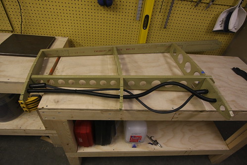
The conduit went very quickly; there's not much to it. Wire tied it to the middle rib anchor point and stuffed it through the two 3/4" holes at the top and bottom.
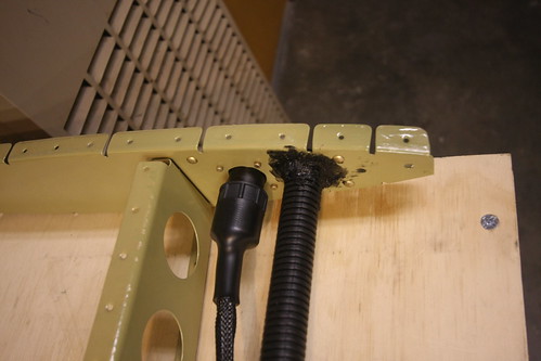
The wiring was considerably more complex. Each wire has crimped sockets attached to each end, the bundle of nine cables is run through a woven abrasion-resistant sheath, and the ends of the cable have heat shrink strain relief boots attached to them.
The trick was getting the length right. The lower forward rib has to be removed during riveting in order to be able to reach the back side of the middle forward rib for bucking the skin rivets. Once this is done, however, the skin is permanently in place and there is no longer access to the top of the lower forward rib to attach the cables into the connector, etc. What I decided to do was go ahead and pre-attach the conduit and cables, but leave enough slack that the lower rib can be detached and moved slightly out of the way—just long enough that a bucking bar and arm can be stuck up in there. When its time to put the lower rib back in place, I'll just push the slack back into the cavity and rivet the rib in place. The conduit slack can be pulled through and the conduit cut to length. The wire harness, unfortunately, cannot. So that slack will remain. I arranged the harness such that the preferential bend in the bundle will push it out towards the leading edge of the skin rather than the forward spar, whose lightening holes could pose an abrasion risk.
6 Nov 2009
A couple of days ago I borrowed a heat gun and some RTV from Bob and finished off the wiring installs in the vertical stabilizer. The VS is now awaiting the grounding studs that are scheduled to arrive on Monday before I can start putting the skins on.
(The remainder of this entry was all rudder stuff.)
12 Nov 2009
Yesterday over lunch I spent an hour and got the bond strap attachement stud attached to the top end of the vertical stabilizer rear spar.
This involved several steps. First, I test-fit the stud and its attachment hardware (including the ring terminal and castle nut). I used a sharpee to mark the footprint of the washers on the spar and doubler so that I'd know where to remove the primer coating. Also marked the appropriate place for a cotter pin hole in the castle nut. All hardware was removed and a Dremel drum sander was used to rip off the primer from where the washers will contact the spar and doubler. This should make for an excellent electrical connection.
Next, all of the aft-side hardware was attached to the threaded rod stud and placed into the hole. A bead of red threadlocker was added to the forward side of the stud and the forward-side hardware tightened down into place. The aft-side hardware was then removed, threadlocker added to this side, and the permanent hardware was tightened back into place. When the threadlocker cures (24 hours), the bonding stud will be permanently in place. I went ahead and added a generous blob of epoxy gel to the foreward side to further hold everything in place. On the aft-side, where the strap ring terminal will attach, I had to be more judicious with the epoxy. I just added enough to cover the exposed aluminum under the washer and add some additional locking to the nut. The top surface of the nut was kept clear of epoxy since this is the electrical bond surface for the strap hardware.
With the bond stud in place, it was finally time to add the skin to the vetical stabilizer. Initially, this just involved clecoing the skin in place. I went ahead and detached the lower nose rib so that the initial rivets in the middle nose rib could be bucked.
Today over lunch, Bob came down and we spent an hour doing rivets. This was Bob's first experience with riveting, and the first rivets to do on that middle nose rib are probably some of the most akward and difficult rivets in the whole plane. But he was very good with the bucking and we managed to get all three nose ribs completed and looking good.
There were a couple small mistakes, minor smilies, etc, but nothing that I'm concerned about. One of them is below the empennage fairing line and the other is small enough that I think a bit of filler will cover it when it comes time to paint.
14 Nov 2009
Yesterday I added the 32 small universal rivets connecting the vertical stabilizer rear spar flanges to the spar caps below the skin. These were straightforward as they can all be squeezed, though I managed to get a few where the head wasn't seated all the way down correctly. The difficulty is that with the pneumatic squeezer and the geometry of the piece, the cupped head of the rivet has to go on the moving part of the squeezer. Thus, as the squeezer is engaged, the entire device has to move relative to the spar flange, rather than the squeezer staying put and just the flush end ramming into the back of the rivet. If this movement isn't conducted just right, the rivet can be pushed out of position a bit before the two ends of the squeezer start applying equal force, resulting in a poorly-seated rivet. I haven't figured out the solution to this yet. For now, I have a few rivets that need to be drilled and re-done.
While waiting for assistance to buck the rest of the skin rivets, I pulled the slack out of the wiring conduit, preventing it from rubbing against anything inside the plane. I put some black RTV on a gloved finger and stuck it through the forward-most lightening hole of the lower nose rib so that I could make a vibration-cancelling fillet where the conduit passes through the doubler, but not visible from the outside. Here is a picture of the inside of the vertical stabilizer. The wire bundle and conduit in the lower-front cavity can be seen through the lightening holes:
Last night, Bob came by with a pizza and we did Dinner & Rivets (soon to be a recurring feature, I hope). Bob acted as the bucking bar placement specialist as we drove the final 218 rivets into the skin. Here he is during the cumbersome bucking of the upper forward spar rivets, which require pealing back the skin a bit and wedging your arm inside.
After about three hours of work, the vertical stabilizer was done! (at least as far as Section 6 of the plans is concerned...)

I'm pretty happy with how it turned out. We went through and examined every visible rivet and marked seven that needed to be replaced because they weren't seated correctly. There are a handfull of smilies and small deformities in the skin from one mistake or another, but nothing that raises a safety concern. I think most of them will be magically whisked away when I give it a once-over with filler prior to priming. Remaining tasks for the vertical stabilizer are now:
29 Nov 2009
The first thing I did today was finish up a few remaining tasks on the vertical stabilizer and rudder. The vertical stabilizer just needed a couple of rivets put in. They were at the bottom of the foreward spar and I had biffed them the first time through, then really mangled the holes trying to drill them out. My solution was to get some big 3/16" AN470 rivets to fill the holes. I drilled out the new big holes with my right-angle drill kit, inserted the big fatty rivets, and drove them home with my 3x rivet gun. No problem. Aside from being huge, they look great. They're probably stronger than the original rivet, so as far as I'm concerned its an improvement. I now pronounce the vertical stabilizer complete until Section 12 (fiberglass fairings) comes along. I taped up the holes in the VS to prevent bugs from getting in, and put it out in the shed for long-term storage.
(the remainder of this entry dealt with the rudder and elevators)
9 Sep 2010
...While I had the dremel cutting wheel out, I went ahead and trimmed down the vertical stabilizer tip fairing flange as well.
For whatever reason, this one had a flange that was about twice as wide as it should have been, so it required a cut all the way around. I didn't like the way the tip of the flange fit inside the skin either, so I trimmed that almost entirely off. All that is left to do with this one before I put it away for the time being is to match drill it and trim the aft edges to clear the rudder counterweight. The aft face build-up, the nutplates, and any potential camera modifications will wait until after the wings (and possibly considerably later).
17 Oct 2010
It's going to be another slow month on the RV-10 front; I've been out of town for most of it thus far, and I'm going to Tanzania here before too long.
I did find time this weekend to put a little work into the vertical stabilizer tip fairing. The first thing I did was to clamp the VS to my workbench, then hang the rudder on it using my temporary attachment pins. Oddly, the center hinge rod end bearing did not line up (it needs to come out about 1/2 turn) despite the center pin dropping right in without effort when these two parts were last joined (during the full empennage attachment out in the driveway). Best guess is that the way the VS is clamped to the bench has introduced a bit of warp to it. Anyway it has no real bearing on what I'm doing right now anyway, so I'll just leave it and adjust as necessary next time I have the full tail assembled (probably a long ways off).
The tip fairing does not stick out aft of the forward top flange of the vertical stabilizer, so no trimming was necessary there. In fact, if anything, it's a bit short and could stand to be built-up a bit. Not a problem, considering that I have to build up the entire aft face of the fairing anyway. I'll leave that for later. Also, the top of the VS fairing is about 3/16" shorter than the top of the rudder fairing. I may build that up if I'm feeling supremely anal later in the build process, or if I run out of money to buy more parts and just want something to do. For now, I'm OK with it. Besides, if I build a forward-facing camera into the top of the VS tip fairing, I'll end up modifying the top edge anyway. So that's probably the right time to worry about the discrepancy.
I made quick work of match-drilling the fairing to the vertical stabilizer, then set about deviating from the plans. The plans call for the use of eight blind rivets to hold the fairing on. I want mine to be removable to be able to access the camera and/or any antennas/lights I may put up there. So I need nutplates. I used basically the same procedure that I had previously done with the bottom rudder fairing.
What were to be #30 rivet holes were drilled out to #21, and #40 holes were added to either side of each to make room for the nutplate rivets. The aft-most hole on each side is too close to the aft edge of the fiberglass, so the nutplate couldn't be mounted horizontal. I could have ordered some one-lug #6 nutplates for this, but it works just as well tilting these corner nutplates to an angle. The two rivets are close to the edge, but it wasn't a problem and I didn't end up with any cracking (except for some hairlines in the gelcoat). Because of the flange lip on the fiberglass, all of the countersinking had to be done with a bare bit and no cage, but this wasn't an issue; it just took a bit longer and required a bit more attention to detail.
Riveting the nutplates on went without a hitch. The VS tip fairing is now ready for the wet fiberglass work on the aft face, and that is going to be tabled until I'm ready to do all of my fiberglass work, or at least until I'm ready to work on the wingtips. So for now I'm done with the empennage fairings chapter and ready to get to work on the wings. The kit should arrive shortly after I get back from Africa.
Time invested on this sub-assembly: 49 hours (42 by me)
The only customization I'm adding to the V.S. is allowing for the possible future addition of a forward-facing camera in the fairing. To achieve this, I'll put a panel-mount CPC into the upper foreward rib and run a cable down to the bottom of the V.S., where another panel-mount CPC will be placed for eventual connection to a cable coming from the fuselage. For the time being, I will not be buying a camera. However, to facilitate putting one into the fairing later, I am modifying the fairing to be removable (i.e. nutplates instead of rivets).
Updates regarding the vertical stabilizer
9 Oct 2009(First part of this entry concerns the tool box practice kit only)
After finishing the box I drove down to Santa Fe for a flight lesson, and what I thought might be my first solo. But it suddenly got so windy that we decided not to fly at all and just walked around the ramp at SAF looking at all the planes. I did manage to put in one whole hour of actual work on the plane—my first actual hour of construction work!
I grabbed all of the vertical stabilizer parts off of the shelf I had reserved for this subassembly, and was pleased to find that everything called out in the plans was there where it should have been. Score one for thorough inventory last night.
A lot of builders have commented on consternation regarding the first step, the long bandsaw cuts on the rear spar caps (VS-1014). I had some concern as well, but mostly because my bandsaw doesn't list aluminum as one of the things it would cut. During the toolbox construction, I tested this by cutting the aluminum hinge to length on the bandsaw and it went through it like butter... so I guessed I was probably good to go on the spar caps. The cuts took a long time but came out looking great.
I did all of the deburring of these two parts on the scotchbrite wheel which went very quickly. The only problem was the enormous amount of warp! It made it hard to mark a straight line (because I had to have the thing clamped in four places to the workbench in order to keep it straight, and the clamps got in the way of the straightedge). It also makes the beginning of step 2 interesting, where you are supposed to nest the spar caps inside the flange of the rear spar. It took 11 clamps before I felt like the spar caps were sitting where they should be in the spar.
That's it for my first day of real construction work. Just one hour.
10 Oct 2009
My 4-day weekend of plane building continues. Spent about 8 hours today on the vertical stabilizer. First up was finishing §6.2.2 which I had started last night. With all the clamps in place, the bendy spar caps weren't an issue. It did require the use of a 1/8" drill bit, which was not included in my tool kit from planetools.com. I thought about just using a #30, which is close, but saw that the instructions have me coming back through with a #30 later for final drilling and figured there's probably a reason. So I ran to the hardware store and picked up a new bit (the only 1/8" bit I had was a wood-cutting bit).
Step three took a ton of time, because for whatever reason I decided to put a cleco in every hole as I went, so when I had to remove the spar caps to deburr the holes, I had to take out about 100 clecos. And then I put them all back in again like a doofus. Look at this ridiculous thing:
The spar doubler cleaned up nicely on the scotchbrite wheel, though I couldn't do the interior surfaces. Those I worked with a file and broke the edges with a pencil deburring tool. As you can see, this time I was a bit more frugal with the clecos (partially because the spar doubler was considerably less bent than the caps).
At this point I removed everything except the caps and deburred all holes. I neglected to mark which hinge half was which before taking them off and had to reassemble them and check before continuing. Small oops, but no biggie. With the hinge parts finished and not needed for the rest of assembly, I left them off along with the VS-1017 hinge doubler for the remainder of today's work. This allowed the vertical stabilizer to lay flat on the aft side of its rear spar, making working on the skeleton and skins easier. The next step was to machine countersink the spar doubler and this was where I made my first significant oops. I got so involved with figuring out where to set the countersink cage for proper depth that I forgot that I only wanted to countersink the holes beneath the upper attach bolt holes. I countersunk eight of the wrong holes before I realized my mistake. Hopefully I can just use AN426 flush rivets here instead of the AN470 called out in the plans. I'll fire off an email to Van's and confirm this. Otherwise, I'll have to order and refabricate a new spar doubler and that will be a pain. For now, this mistake does not prevent me from continuing with the fabrication of the vertical stabilizer. Not a great way to finish my first page of the plans, but that's it! Page §6.2 complete (sort of)!
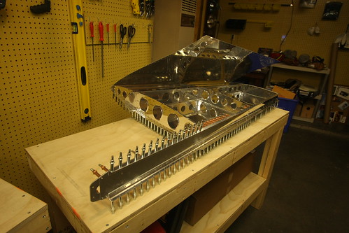
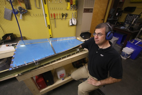
I deburred the rest of the skeleton parts on the scotchbrite wheel and used the pencil tool on the lightening holes. Worked great. Paid special attention to the nose rib points, which I ground down about 3/16" so as not to dimple the skin leading edge when I fold it over the skeleton. Onec that was done, I went ahead and assembled the skeleton with the rear spar clamped to a leg of my workbench:
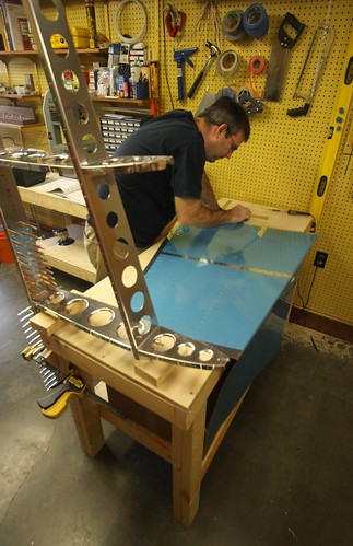
It was really wobbly. It was really disconcerting how little structural stability this skeleton has with no skin on it. Whereas the rear spar is solid as a rock with those caps and doubler in there, the rest of the parts are just wibbly and I feel like it was going to fold under its own weight. Yikes. Anyway, I thought it would be cool to work on the assembly in its natural upright position, but this came to a rapid end as I needed to final drill those holes on the top rib where it connects to the front spar, and with it clamped to the bench like this, those holes were about six feet off the floor! It made for a cool picture, anyway.
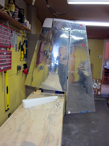
Back on the table, I got the skeleton final drilling out of the way and prepared to put the skin on! First, I had to remove the vinyl from the inside surface. This proved to be harder than I thought it would be. Removing the vinyl from the other parts had been reasonably straightforward. Here I ended up having to wrap the vinyl around a broom handle and rolling that up to pull the coating off. It seemed a lot more sticky than the other parts. Took about 10 minutes just to get the vinyl off that one part. Then, another short bit of instructions that takes forever. "Clecko the skin to the skeleton" translated into about two hours of work. I'm not sure why I had such a hard time with this, but everything I was trying was not working. The hardest part was getting the holes to line up on the middle nose rib. In the end, what worked the best was doing the clecos on one side for everything but the middle nose rib, then turning the assembly over.
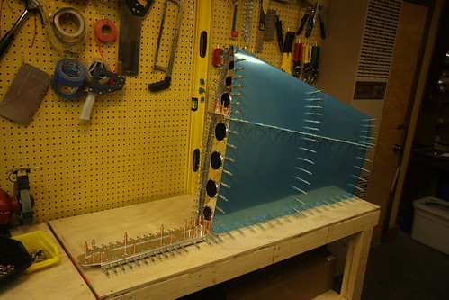
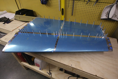
Next, I helt a cleco in the hole for the forward-most hole in the skin for the nose rib, then with my other arm I reached under the skin and wiggled the rib back and forth until I got the cleco to drop. It was a giant pain, but it was only required for the five or six rivets on the one side of that nose rib. Once that was done, everything else went into place pretty easily. I finished up with clecoing the skin to the skeleton and called it a night. The result looked something like this:
It's nice to have something that vaguely resembles a plane part on the bench! Also, it was pleasing to note that with the skin on, the stabilizer was rock solid, not the miserable flimsy thing the skeleton had been. First thing tomorrow will be §6.3.4: match-drilling each and every hole in the skin. Unfortunately, after that step, the whole assembly comes apart again for awhile.
11 Oct 2009
Most of the six hours of work that got done today involved things that don't have much visual impact on the vertical stabilizer at all. A lot of dimpling, deburring, and match-drilling parts that were already together. Probably the most visually striking thing that happened was when I removed some strips of vinyl from the front of the VS skin. Bob came by to check out the project so I put him to work helping me get the vinyl strips off.
Aside from the vinyl modification, I got all of the skin holes match drilled and deburred. I also deburred all of the skin/skeleton interface holes on the skeleton. I then started the dimpling. Got all of the skeleton holes dimpled, but gave up on trying to dimple the skin by myself since Bob said he'd help over lunch tomorrow and it'll be a lot easier with two people. The skeleton dimpling required all three of my available dimpling techniques! Most of it was done on the DRDT-2 dimpler (which I love), but a few of the corner holes and holes in the narrow pieces wouldn't work there, so I broke out the pneumatic squeezer and took care of the rest—except for the forward two holes on the top rib, for which even the squeezer wouldn't do. For these, I had to use the pop rivet tool and the nail/dimple die combo. Worked like a champ.
Also took care of countersinking the rear spar/skin interface holes where called out in §6.3.8. With the exception of the skin dimples, the next step is to disassemble the rear spar bits. This will be the last time the spar is together before the parts are primed, so I am likely to hold on doing §6.3.9 until I figure out a few of the customizations I'm going to be adding to this subassembly. In particular, I need to figure out where and how to mount the braided copper grounding straps that will run between the VS and the rudder.
12 Oct 2009
The last day of my four day RV-10 superweekend.
Spent the morning finishing minor tasks like preparing the rudder stops and match-drilling the hinges, etc. When Bob showed up on his lunchbreak, we made quick work of the skin dimpling. The very front hole in the middle rib was not reachable with the DRDT-2 so I had to pop-dimple that one. Otherwise we knocked it out in about 10 minutes and went out for Chinese food.
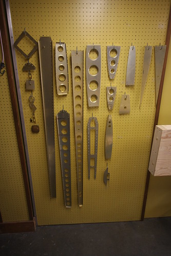
Spent the rest of the day working on some custom parts for my electrical run to the vertical stabilizer fairing. I know I want to mount a camera up there someday, and I have vague notions of someday flying internationally with this thing which means I may need an HF antenna—the top of the tail is a logical place for one end of a longwire antenna on a plane. So I'm running a harness of cables from inside the VS fairing to the base of the VS with circular plastic connectors on each end to facilitate hooking up accessories in the future without having to do a tricky cable run. I also am going to run an empty conduit up to the top in case I want to run an antenna cable but don't want to have lossy connectors in line.
To pull this off, I need doublers at both the top and bottom nose ribs and some way to keep the conduit and cables off the lightening hole edges on the middle nose rib.
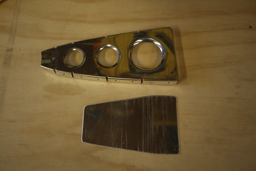
Here is the doubler plate I whipped up for the bottom nose rib. I know it's unnecessarily huge... but whatever it's light. I drilled out holes for the connector and conduit, and rivet holes to attach it to the nose rib and ended up something like this:
For the middle nose rib I found the perfect product—a wire tie bracket made especially for riveting onto lightening holes. How perfect? I just had to drill two small rivet holes in the middle nose rib.
For the top rib I had to make a much more compact doubler since the rib itself is so small. I had concerns about so many holes in such a small piece, but the technical support people at Van's said they didn't forsee any problem with this.
That's about it for today. Only about five hours of actual work. At this point, I am at §6.4.5 which states, simply, "prime the parts." This is going to take some infrastructure preparation so it may be awhile before significant progress occurs on the vertical stab.
29 Oct 2009
A bunch of random things have occurred in the last week. After reading up on other builders websites, I determined that I wouldn't be making the bend in the trailing edge of the rudder at all. I'll be using the angle iron backrivet technique and tank sealant to ensure a good bond at the trailing edge.
Making this decision cleared me to finish up the rudder skins. I removed the vinyl coating from the rivet lines and Bob assisted with the dimpling of all the holes. The next step on the skins will be to scuff the inner surface, clean it, and then prime it.
I spent a lot of time thinking about how to do bond straps between the rudder and vertical stab. I was unable to find appropriate ring terminals, bolts, washers, and nuts in aluminum... so I've decided to use passivated cadmium-plated steel hardware instead and hope for the best. I ordered some candidate pieces from Aircraft Spruce and they look like they might work. I also ordered hardware for making the vertical stabilizer and lower rudder fairings removable via nutplates. Unfortunately I based my parts decisions here on another builder's website who had a typo in their part numbers! I ordered thirty K1000-6 nutplates instead of K1000-06 nutplates without checking the bolt size vs. nutplate size. That's a $50 oops! Reordered the correct nutplates from Van's. They'll be here long before I'm ready for them. If anyone needs any of the huge K1000-6 nutplates... let me know.
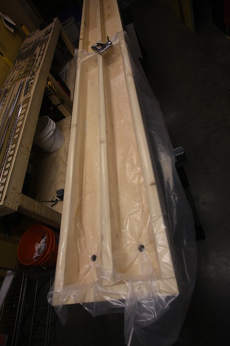
The other major accomplishment of this week was building the dunk tank for doing alumiprep and alodine chemistry on the long thin parts of the aircraft. I didn't want to have to build more than one of these, so I made it really long to accomodate the longest pieces of the airplane. Right now, the longest parts I know of are the horizontal stabilizer spars, which come in at about 11'6" each. I bought three twelve foot 2x4s and made a simple double-trough frame out of them. I used the plywood from the empennage delivery crate for the bottom of the troughs, and a four foot spare piece of 2x4 from the workbench assembly for the end caps. Drilled drain holes in one end and fashioned a couple of 2x4 blocks to allow for length customization, saving on chemical volume when working on parts shorter than the horizontal stabilizer spars.
Above is a picture of the finished dunk tank with the length blocks set at about six feet, just longer than the longest parts in both the rudder and vertical stabilizer. I then lined the active side of the tank with 4 mil plastic sheet and poked it down through the drain holes. I used a staple gun to temporarily keep the sheet in place. The dunk tank is ready to go! More pictures here.
The last thing I did was to rig up hooks and line for allowing the parts to air dry after the alumiprep and alodine washes are complete. Currently all of the parts for both the vertical stabilizer and rudder and hanging in the shop. The only thing I'm missing before I proceed with the chemistry is buckets to reclaim the used water and chemicals. Should be able to pick those up at the local hardware store. Then, it'll be time for SCIENCE!
31 Oct 2009
Got three sealable five-gallon buckets this morning, one for alodine, one for alumiprep, and one for distilled water. The Alodine comes by the gallon and gets mixed 1:2 with water, for a total of three gallons of solution. The Alumiprep also comes by the gallon and gets mixed 1:3 with water, for four gallons of solution. I pre-mixed these and labeled their respective buckets.
With the adjustable blocks in my dunk tank set at just over five feet (the length of the rudder spar), and each trough being six inches wide, three gallons was enough for an almost two inch deep pool of Alodine. I only used about three gallons of the Alumiprep as well.
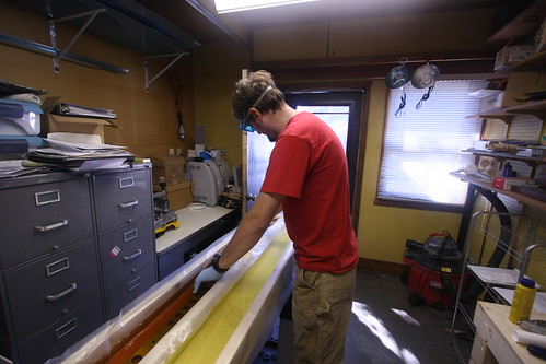
The process of immersing the parts in each bath and then drying went surprisingly quickly. I was able to prep and alodine all of the parts for both the vertical stabilizer and rudder in about two hours including setup and cleanup. Also, this was my first time figuring out how everything would work, so I took a lot longer on some steps than I will require when I do this again for the horizontal stabilizer.
All of the parts now have that great golden finish to them and are ready for priming.
2 Nov 2009
Quite a bit has happened over the past two days. For starters, I primed all of the rudder and vertical stabilizer parts. Riveting together of the vertical stabilizer skeleton has also been started. Here's me about to stat priming all of the non-skin parts.
And here's all of the parts, including the skins, drying after being primed with Akzo 2-part epoxy primer.
Once everything had dried for a few hours, I started in on the vertical stabilizer riveting. The very first rivet in the plane was between the lower rudder hinge bracket and the rudder stop. Unfortunately, I was excited about doing some riveting and failed to follow the instructions; I did all six of these rivets with the second hinge bracket in there too. Not right. Had to drill them all out and start over. Whoops! Once I got past that little snafu, I riveted together the VS rear spar, spar caps, doublers, and rudder hinges. This took a grand total of 75 rivets, almost all of which could be done with the squeezer. The universal rivets that attach the hinges closest to the corner of the hinge have to be done with the rivet gun and bucking bar, and I cleated one of these. Had to drill it out and replace it.
I didn't put on the upper half of the upper hinge bracket, or the upper middle rivet on the upper hinge doubler because I want to replace this rivet with a mounting bolt for a bond strap to run between the VS and the rudder. I'm still having problems figuring out what the right bolt/nut/ring terminal combination is for this, so that bit is on hold. Below is a photo of the upper hinge area showing the unfinished rivets. I also have an AN3-4 bolt there with a castle nut, ring terminal, and some washers there for sacle. The problem with the AN series bolts is that the threaded section is just too short to have a permanently-attached bolt/nut combo and then a removable ring terminal/castle nut combo on top of that. I'm looking for a slightly longer bolt with a shorter grip, and it has to be passivated. So far, no joy.
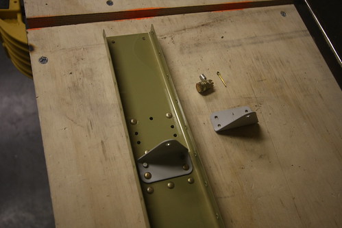
Tabling the rear VS spar for now, I moved on to the forward VS spar, which needs very little treatment. Just 10 rivets for the doubler—four flush and six universal. I used the squeezer on the universals which was a breeze, and then used my new back riveting plate on the flush which was also quite straightforward. Nina was around while I was doing this, so I showed her how to use both the squeezer and the rivet gun. She did four of the rivets on this part and they all look great.
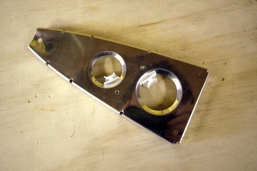
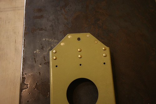
From there, it was time for the customizations to the forward ribs for the wiring and conduit runs. First up was the lower rib, which got a custom doubler plate and the circular plastic connector riveted into the doubler:
Then the top rib doubler and CPC. Here I made a small mistake; I meant to put the doubler on the bottom of the rib, but forgot that this rib gets installed flanges-up. By the time I had noticed, the doubler was already fully riveted into the web. Not a big problem; but you can still read my sharpee'd "bottom" notation on the top of the doubler. No big deal, bit I need to be more careful. Too many mistakes.
Last up was the forward middle rib, which just got two wire tie anchors riveted into the two lightening holes. One will secure the conduit, the other the wire bundle.
I'll probably go ahead and rivet up the rest of the VS skeleton soon since I can still do the grounding post modification after the skeleton is assembled. Riveting on the skin will have to wait for the bolt issue to be resolved, however.
3 Nov 2009
Riveted together the skeleton pieces (except for the lower inspar and forward ribs, as per the instructions). This required only 11 rivets, eight of which could be squeezed, so it went very quickly. The rest of the session was spent routing cables and conduit.
The conduit went very quickly; there's not much to it. Wire tied it to the middle rib anchor point and stuffed it through the two 3/4" holes at the top and bottom.
The wiring was considerably more complex. Each wire has crimped sockets attached to each end, the bundle of nine cables is run through a woven abrasion-resistant sheath, and the ends of the cable have heat shrink strain relief boots attached to them.
The trick was getting the length right. The lower forward rib has to be removed during riveting in order to be able to reach the back side of the middle forward rib for bucking the skin rivets. Once this is done, however, the skin is permanently in place and there is no longer access to the top of the lower forward rib to attach the cables into the connector, etc. What I decided to do was go ahead and pre-attach the conduit and cables, but leave enough slack that the lower rib can be detached and moved slightly out of the way—just long enough that a bucking bar and arm can be stuck up in there. When its time to put the lower rib back in place, I'll just push the slack back into the cavity and rivet the rib in place. The conduit slack can be pulled through and the conduit cut to length. The wire harness, unfortunately, cannot. So that slack will remain. I arranged the harness such that the preferential bend in the bundle will push it out towards the leading edge of the skin rather than the forward spar, whose lightening holes could pose an abrasion risk.
6 Nov 2009
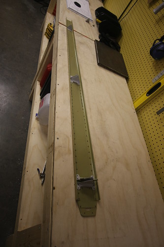
A couple of days ago I borrowed a heat gun and some RTV from Bob and finished off the wiring installs in the vertical stabilizer. The VS is now awaiting the grounding studs that are scheduled to arrive on Monday before I can start putting the skins on.
(The remainder of this entry was all rudder stuff.)
12 Nov 2009
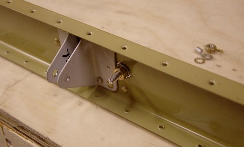
Yesterday over lunch I spent an hour and got the bond strap attachement stud attached to the top end of the vertical stabilizer rear spar.
This involved several steps. First, I test-fit the stud and its attachment hardware (including the ring terminal and castle nut). I used a sharpee to mark the footprint of the washers on the spar and doubler so that I'd know where to remove the primer coating. Also marked the appropriate place for a cotter pin hole in the castle nut. All hardware was removed and a Dremel drum sander was used to rip off the primer from where the washers will contact the spar and doubler. This should make for an excellent electrical connection.
Next, all of the aft-side hardware was attached to the threaded rod stud and placed into the hole. A bead of red threadlocker was added to the forward side of the stud and the forward-side hardware tightened down into place. The aft-side hardware was then removed, threadlocker added to this side, and the permanent hardware was tightened back into place. When the threadlocker cures (24 hours), the bonding stud will be permanently in place. I went ahead and added a generous blob of epoxy gel to the foreward side to further hold everything in place. On the aft-side, where the strap ring terminal will attach, I had to be more judicious with the epoxy. I just added enough to cover the exposed aluminum under the washer and add some additional locking to the nut. The top surface of the nut was kept clear of epoxy since this is the electrical bond surface for the strap hardware.
With the bond stud in place, it was finally time to add the skin to the vetical stabilizer. Initially, this just involved clecoing the skin in place. I went ahead and detached the lower nose rib so that the initial rivets in the middle nose rib could be bucked.
Today over lunch, Bob came down and we spent an hour doing rivets. This was Bob's first experience with riveting, and the first rivets to do on that middle nose rib are probably some of the most akward and difficult rivets in the whole plane. But he was very good with the bucking and we managed to get all three nose ribs completed and looking good.
There were a couple small mistakes, minor smilies, etc, but nothing that I'm concerned about. One of them is below the empennage fairing line and the other is small enough that I think a bit of filler will cover it when it comes time to paint.
14 Nov 2009
Yesterday I added the 32 small universal rivets connecting the vertical stabilizer rear spar flanges to the spar caps below the skin. These were straightforward as they can all be squeezed, though I managed to get a few where the head wasn't seated all the way down correctly. The difficulty is that with the pneumatic squeezer and the geometry of the piece, the cupped head of the rivet has to go on the moving part of the squeezer. Thus, as the squeezer is engaged, the entire device has to move relative to the spar flange, rather than the squeezer staying put and just the flush end ramming into the back of the rivet. If this movement isn't conducted just right, the rivet can be pushed out of position a bit before the two ends of the squeezer start applying equal force, resulting in a poorly-seated rivet. I haven't figured out the solution to this yet. For now, I have a few rivets that need to be drilled and re-done.
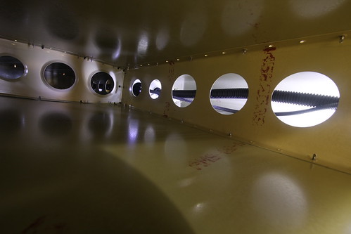
While waiting for assistance to buck the rest of the skin rivets, I pulled the slack out of the wiring conduit, preventing it from rubbing against anything inside the plane. I put some black RTV on a gloved finger and stuck it through the forward-most lightening hole of the lower nose rib so that I could make a vibration-cancelling fillet where the conduit passes through the doubler, but not visible from the outside. Here is a picture of the inside of the vertical stabilizer. The wire bundle and conduit in the lower-front cavity can be seen through the lightening holes:
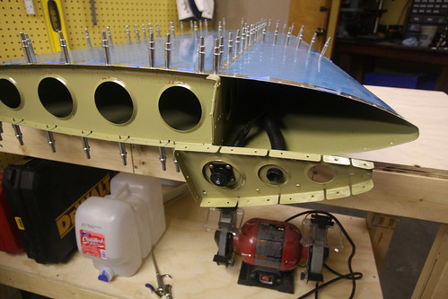
Last night, Bob came by with a pizza and we did Dinner & Rivets (soon to be a recurring feature, I hope). Bob acted as the bucking bar placement specialist as we drove the final 218 rivets into the skin. Here he is during the cumbersome bucking of the upper forward spar rivets, which require pealing back the skin a bit and wedging your arm inside.
After about three hours of work, the vertical stabilizer was done! (at least as far as Section 6 of the plans is concerned...)
I'm pretty happy with how it turned out. We went through and examined every visible rivet and marked seven that needed to be replaced because they weren't seated correctly. There are a handfull of smilies and small deformities in the skin from one mistake or another, but nothing that raises a safety concern. I think most of them will be magically whisked away when I give it a once-over with filler prior to priming. Remaining tasks for the vertical stabilizer are now:
- Fix the seven bad rivets
- Attach to the rest of the empennage (this happens in Section 11)
- Add the tip fairing (this happens in Section 12)
- Outer surface treatment (filler, primer, paint, etc; this happens when the plane is structurally complete)
29 Nov 2009
The first thing I did today was finish up a few remaining tasks on the vertical stabilizer and rudder. The vertical stabilizer just needed a couple of rivets put in. They were at the bottom of the foreward spar and I had biffed them the first time through, then really mangled the holes trying to drill them out. My solution was to get some big 3/16" AN470 rivets to fill the holes. I drilled out the new big holes with my right-angle drill kit, inserted the big fatty rivets, and drove them home with my 3x rivet gun. No problem. Aside from being huge, they look great. They're probably stronger than the original rivet, so as far as I'm concerned its an improvement. I now pronounce the vertical stabilizer complete until Section 12 (fiberglass fairings) comes along. I taped up the holes in the VS to prevent bugs from getting in, and put it out in the shed for long-term storage.
(the remainder of this entry dealt with the rudder and elevators)
9 Sep 2010
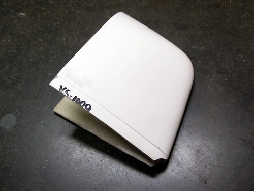
...While I had the dremel cutting wheel out, I went ahead and trimmed down the vertical stabilizer tip fairing flange as well.
For whatever reason, this one had a flange that was about twice as wide as it should have been, so it required a cut all the way around. I didn't like the way the tip of the flange fit inside the skin either, so I trimmed that almost entirely off. All that is left to do with this one before I put it away for the time being is to match drill it and trim the aft edges to clear the rudder counterweight. The aft face build-up, the nutplates, and any potential camera modifications will wait until after the wings (and possibly considerably later).
17 Oct 2010
It's going to be another slow month on the RV-10 front; I've been out of town for most of it thus far, and I'm going to Tanzania here before too long.
I did find time this weekend to put a little work into the vertical stabilizer tip fairing. The first thing I did was to clamp the VS to my workbench, then hang the rudder on it using my temporary attachment pins. Oddly, the center hinge rod end bearing did not line up (it needs to come out about 1/2 turn) despite the center pin dropping right in without effort when these two parts were last joined (during the full empennage attachment out in the driveway). Best guess is that the way the VS is clamped to the bench has introduced a bit of warp to it. Anyway it has no real bearing on what I'm doing right now anyway, so I'll just leave it and adjust as necessary next time I have the full tail assembled (probably a long ways off).
The tip fairing does not stick out aft of the forward top flange of the vertical stabilizer, so no trimming was necessary there. In fact, if anything, it's a bit short and could stand to be built-up a bit. Not a problem, considering that I have to build up the entire aft face of the fairing anyway. I'll leave that for later. Also, the top of the VS fairing is about 3/16" shorter than the top of the rudder fairing. I may build that up if I'm feeling supremely anal later in the build process, or if I run out of money to buy more parts and just want something to do. For now, I'm OK with it. Besides, if I build a forward-facing camera into the top of the VS tip fairing, I'll end up modifying the top edge anyway. So that's probably the right time to worry about the discrepancy.
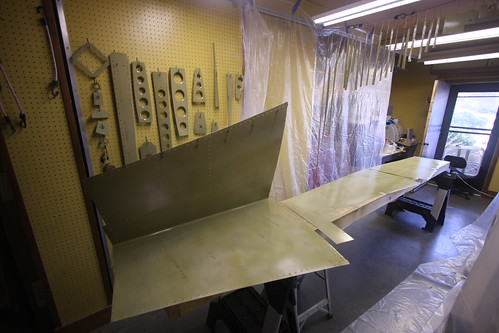
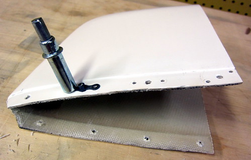
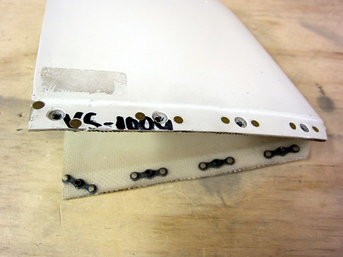
I made quick work of match-drilling the fairing to the vertical stabilizer, then set about deviating from the plans. The plans call for the use of eight blind rivets to hold the fairing on. I want mine to be removable to be able to access the camera and/or any antennas/lights I may put up there. So I need nutplates. I used basically the same procedure that I had previously done with the bottom rudder fairing.
What were to be #30 rivet holes were drilled out to #21, and #40 holes were added to either side of each to make room for the nutplate rivets. The aft-most hole on each side is too close to the aft edge of the fiberglass, so the nutplate couldn't be mounted horizontal. I could have ordered some one-lug #6 nutplates for this, but it works just as well tilting these corner nutplates to an angle. The two rivets are close to the edge, but it wasn't a problem and I didn't end up with any cracking (except for some hairlines in the gelcoat). Because of the flange lip on the fiberglass, all of the countersinking had to be done with a bare bit and no cage, but this wasn't an issue; it just took a bit longer and required a bit more attention to detail.
Riveting the nutplates on went without a hitch. The VS tip fairing is now ready for the wet fiberglass work on the aft face, and that is going to be tabled until I'm ready to do all of my fiberglass work, or at least until I'm ready to work on the wingtips. So for now I'm done with the empennage fairings chapter and ready to get to work on the wings. The kit should arrive shortly after I get back from Africa.