
| Workshop | Empennage | Wings | Fuselage | Contact |
Tail Cone Construction
Part 2 of 3
(see also part 1 and part 3)
25 Mar 2010
It's been awhile! I've been out of the country for three weeks, so there hasn't been a lot going on with the plane. I did manage to do one small modification before I left; I enlarged the cutouts in the frames where the longeron passes through so that they weren't rubbing against each other anymore and the frame flange was able to press up flush against the skin like it should. Did the enlarging with a dremel reamer bit.
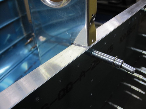
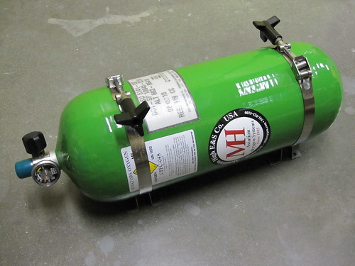
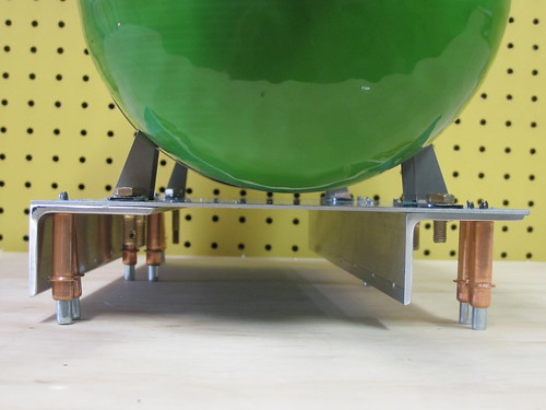
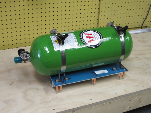
Also, before I left, I put in some major orders for tail cone accessories. Stuff that isn't part of the plans but that I need to figure out the mounting logistics for before I prime the tail cone parts. The most significant accessory is the built-in oxygen system. I went with a CFFC-048 tank which holds 48 cubic feed of oxygen, a pneumatically controlled regulator, an electronic pressure transducer and associated 1.5" panel gauge, and a refill station with integrated pressure readout. Here is the tank:
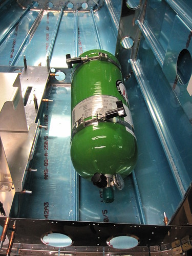
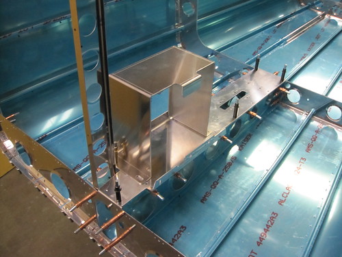
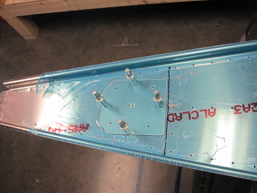
And here's where I'm planning to mount it (roughly). I'll be building a little platform for it to bolt down to which will attach to the J-stiffeners on the bottom skin.
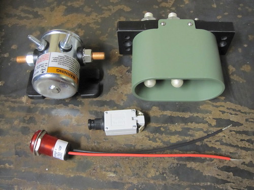
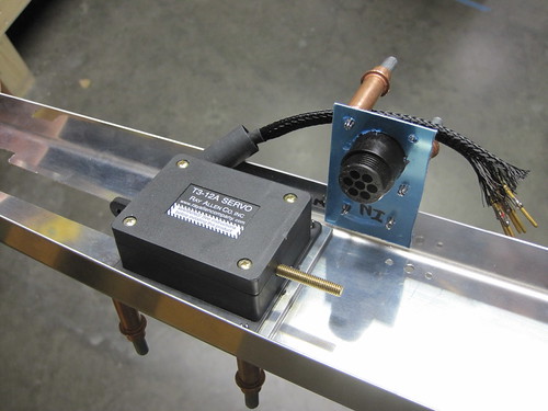
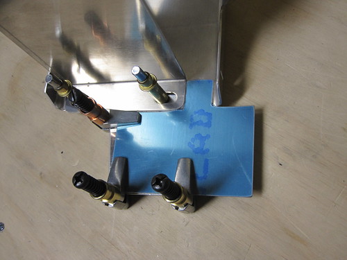
In addition to the oxygen system, I also got the parts for my external power subsystem. This includes the jack itself, a contactor, a pull breaker, a large LED to indicate contactor status, some polarity protection diodes, and a crowbar overvoltage protection module. Shown below is everything except the crowbar and the diodes.
I also got a battery box made specifically for the Odyssey 925 battery I intend to use. It will bolt down onto the battery tray as seen below:
See the tail cone photo gallery to see pictures of the bits not shown here, including the PCR, the oxygen fill port, the pressure gauge, some of the oxygen plumbing hardware, and the main battery hot bus fuse block.
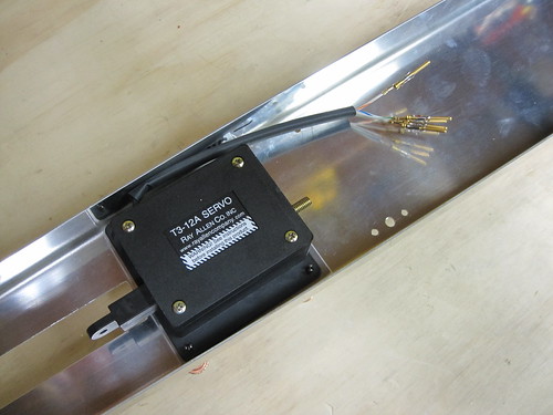
Last night I got started on the elevator trim servo wiring though I didn't get very far. I put some heat shrink over the wire bundle and crimped pins on to the 26AWG wires for later insertion into a CPC. I don't have my own heat gun, so I ordered one and I'm waiting on it to arrive before I can shrink the tubing.
I still need to fabricate a drop plate on the flange of the elevator trim bracket to hold the CPC and possibly order a strain relief device for the back side of the CPC, though I may just go with some RTV.
So not a lot of work on the plane in the last month, but lots of new bits and pieces to start mounting!
1 Apr 2010
No, it's no April Fool's joke, I actually found time to do more work on the plane!
I spent a lot of time while I was out of the country doing some planning for the tail cone accessories and the steps required to install each. Tonight I put those steps in a sensible order, and drew a line on each list at the point where I would need to disassemble the tail cone before continuing. Everything above that line is now on the critical path. This evening I spent some time getting the elevator trim servo bracket assembly and static air system lists down to the disassembly-required line.
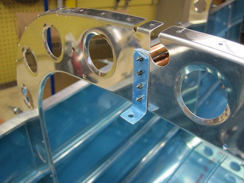
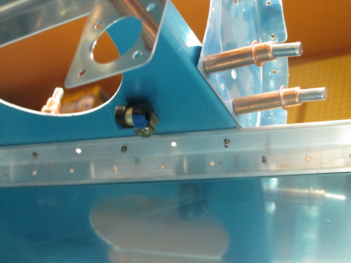
First, I fabricated a small bracket that sits aft of the rivet line that attaches the two halves of the frame that sits just aft of the static airports. This bracket will support the T-junction that joins the two sides of the static air system. Here it is cleco'd to the frame:
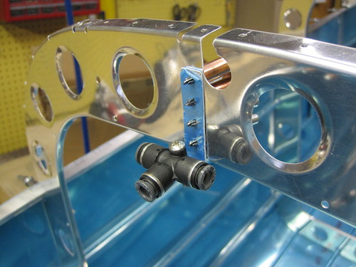
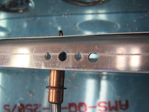
I discovered that if I put the 90° elbows coming right off the static ports facing aft, they poke right through the lightening holes in the frame. This allows me to plumb all of the static line and associated clamp hardware to the aft of the frame. This, in turn, keeps all of it out of the way of the skin rivets associated with the frame, which are all on the front side. That means that I can go ahead and run the static lines up as far as the T junction before riveting on the top skin, preventing me from having to crawl inside the dark enclosed tail cone to do it later. Here is a picture of the T-junction temporarily installed on its bracket:
Next, I fabricated a little drop plate to hang off the side of the elevator trim servo bracket. It holds a panel-mount circular plastic connector for the five servo control and sense wires.
With it fabricated, the elevator trim servo bracket parts are all ready for priming. One more small modification regarding elevator trim was to add a hole in the aft deck for an Adel clamp on the bottom face of the deck. This clamp will be the last support for the cable that will eventually connect to to the CPC in the drop plate.
The only other thing I did tonight was to mark some hole positions on the F-1028 channel for Adel clamps that will hold the top conduit on one side and the wire bundle coming out of the overhead console on the other. After marking the holes, this section was ready for disassembly as well and was moved off the critical path list.
Accessory assemblies still on the list of things to do before disassembly:
4 Apr 2010
Did a short stint of work today on the Odyssey PC925 battery box. This part replaces the two battery tray side bars, the hold-down bar, and the two hold-down bolts of the RV-10 kit. Unfotunately, it doesn't match the hole pattern for the kit's side bars. I went ahead and lined up one hole (the front right one) just to save work. This kept the right-side holes aligned over the rib rail beneath the battery tray for support. However, the left-side holes were well inside of the left rib rail so they'll have less support. I started off by drilling a new #12 hole for the front-left battery box hole, then adding countersunk rivet holes for a K1000-3 nutplate on the bottom of the batter tray.
The forward-left corner becomes problematic. What was originally the forward-left hole for the battery tray side bar is now unused. But it is the only thing nearby that secures the battery tray to the rib rail underneath. So I'd really like to just put a bolt in there anyway. However, the hole is too close to the edge of the battery box to accept a bolt head.
I thought about making a shim that is the same thickness as the battery box flange and then bolting that down, but I think instead I'll just make part of the airframe ground bracket (which will eventually be attached in the blank area of the battery tray just forward of the battery box) stick out over this spot and act as a shim. Either way, both the new and the old battery hold-down holes will have bolts in them.
Turning to the aft end of the battery box, we have even more problems.
First, the aft-left hole required a new set of nutplate holes which are also not supported by the rib rail. Again, the existing hole is now too close to the box to accept a bolt directly (though in this case filing down the corner of the box may suffice). The bigger problem is on the aft-right side, where the new hole through the battery tray and the rib rail beneath is too close to the existing nutplate rivet hole for the old side bar hole.
I'll have to add a nutplate for this hole that only has one lug, and I don't have any of those in the correct size. So that bit is on hold awaiting more parts.
Actually, everything is now on hold awaiting more parts. I spent a bit of time this evening thinking about exactly what I need to finish all of the accessories mounting in the tail cone, and came up with a big list of hardware, tools, and parts that I needed to buy. $180 later, I'm now on hold. And it probably won't arrive before I'm off galavanting around the world again next week. So this may be the sum total of the work that gets done on the plane in April. Oh well... slow progress is still progress.
4 May 2010
Out of the country for another three weeks there, now I'm back with a powerful case of jetlag. Didn't want to engage in anything too complex since my brain is still somewhere over eastern Europe, so I spent some time (between three and five in the morning) fabricating the airframe ground bracket.
The wiring harness plans (OP-37?) call for putting a bolt through this piece of the battery tray and attaching a 2 AWG wire from the battery ground terminal to the bolt, thus connecting the airframe to the electrical ground system. This allows things like lights and pitot heat to be connected to ground locally rather than having to run heavy ground wires around for these high-current sources. However, because of all the accessories I'm loading into the tail cone, in particular the external power socket, I need quite a few grounds to come together here. The two coming from the external power socket and the battery are both 2 AWG, and I didn't want to try to load all of that onto one bolt.
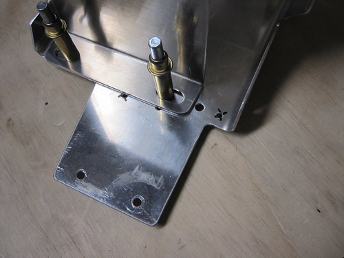
In addition, I wanted the grounding bolts to be mounted horizontally rather than the suggested vertical arrangement, which I think will make my wiring look a little cleaner in this area. I have seen other builders put a piece of aluminum angle here and bolt into that, so I started designing something like that. Another design goal of mine was to be able to use the original forward-left battery hold-down bolt hole to help with the new battery box. As you can see from the photo, above, the old hole is right up against the edge of the battery box, so I wouldn't be able to fit a washer on there. I considered grinding down some washers to fit that space, but instead decided to just extend the grounding bracket to include a tab that sticks out into this space. Using metal of the same thickness, I can now put a washer and bolt into that hole and it would clamp down the box and take advantage of the rib rail beneath the original hole (the new hole just has the tray and no support underneath). With this in mind, I cut out a piece of 0.063" aluminum (the closest sheet thickness I could find to the thickness of the battery box) that looks like this:
The wide tab on the left side (right in this image) will get bent upwards and the grounding bolts will attach to this. Looking at the bottom of the battery tray with the new piece clamped in place, you can see the three bolt holes that they share:
The small hole in the upper-left of this photo will not be used and thus will not be match-drilled into the grounding bracket. The two holes at the bottom of the photo are for the bolts that attach the battery tray to the F-1006 frame. After match-drilling these three bolt holes, the bracket looks like this:
Because the battery tray must be removable from the completed plane in order to allow maintenance on the elevator pushrod system, there can be no rivets that attach the tray to any of the other stock airframe. I wanted to rivet the grounding bracket to the tray, however, to increase the electrical connectivity between the two. To achieve this, I drilled six holes between the two parts for 1/8" rivets in a spot that was clear of the underlaying rib rail and F-1006 tab. I also used a hand-seamer to put a 90° bend in the bracket to match the adjacent flange on the battery tray.
Most of the grounding bracket won't get primed so that there is a good electrical connection between the bolt heads and the bracket. Before priming the rest of the battery tray (but after alodining both parts), I will rivet these six holes with AN470 hardware. Then I'll mask the parts that don't get primer and spray it down.
The next task was to drill some holes for anchor nuts that would hold the actual grounding bolts, but I had a brain wave at the last moment that caused me to change my design a bit. I was thinking of two large AN4 bolts for the battery and external power connector 2 AWG lines, pluse a third AN3 bolt for the assorted low-current ground returns that come here (overhead console lighting, external power relay control, etc.). However, having a bunch of wires returning to a threaded post like that, each with its own ring termianl, is going to get ugly fast. Instead, why not use a small "forest of tabs" style grounding buss attached right to the bracket. SteinAir sells a nice 10-tab version that is only a couple inches long. I've got one on order now, and when it arrives I'll figure out a way to attach it to the base of the grounding bracket, then I can route up to 10 small-gauge grounding wires here cleanly. Until it arrives, this piece is on standby.
6 May 2010
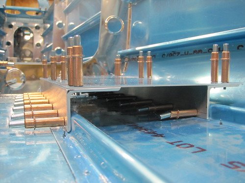
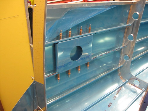
Today I knocked out most of the oxygen tank mount hardware. I had been planning to put the tank on the left-side wall, attaching it to the D and E stiffeners. However, I noticed that the documentation for the tank clamps indicates that it supports considerably less side-loading than it does up-and-down loading. And since the highest forces likely to be encountered are landing shocks (oriented in the vertical axis), I wanted to orient the tank such that the clamp feet were on the bottom (or top...) of the tank. As a result, I moved my design to the work with the outer two J-stiffeners on the left side of the bottom skin of the tail cone, in the bay between the F-1006 and F-1007 frames.
The first step was to fabricate two 14" lengths of 1.5" x 2" x 0.125" angle aluminum. The reason I used such a large angle was because the stiffeners aren't parallel. Thus, if I align the feet with an edge on one angle bracket, the feet will be skewed on the other and require a larger landing. I drilled seven holes, every two inches, a quarter inch above the edge of the shorter side of each angle. Then I used my right-angle drill kit to match-drill these holes into the J-stiffener flanges.
When I cleco'd the angle brackets into place, I could see that the J-stiffener flanges were not perpendicular to the bottom skin. As a result, the two "horizontal" parts were not co-planar.
This wasn't a big problem, because a gentle push on the horizontal parts would bend the stiffener flange slightly and result in good alignment between the two brackets. I decided to fashion a plate to connect the two angle brackets and ensure that they were laying co-planar. This worked like a charm and didn't impose too much stress on the J-stiffeners.
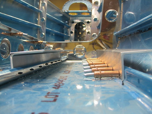
I added a series of twelve 1/8" holes for eventual rivets between the top plate and the angle brackets. From here, it was simply a matter of match-drilling the feet of the oxygen tank clamp into the angle brackets and top plate. Eight 1/4" holes later, the tank could be bolted onto to the brackets.
In the picture above, the bolts are just stuck through the holes with no nuts or anything. Also, they are all different lengths because I haven't bought hardware for this yet. My plan is to put K1000-4 nutplates on the underside of the angle brackets to capture the eight bolts. AN4-5A bolts should be perfect.
Technically, with the clamp feet bolted into the nutplates, the twelve rivet holes become redundant. Also, once rivets are put in place there, the top plate is no longer removable. On the off chance that I decide to run some wires underneath this assembly and want to attach an adel clamp to the bottom side of the top plate, I will probably leave these rivet holes empty at least until wiring is complete, if not forever. They were just there to hold everything square with clecos while I drilled out the bolt holes.
9 May 2010
Big day today, culminating with the long-awaited return to following the plans after having finished fabrication tasks for the custom accessories.
First up was to match-drill a mounting bracket for the ELT into the right-side stiffeners. This was a quick job. I don't have the ELT yet (it is still on backorder and has been for many months), but when I get it I can just figure out how to get its quick-release plate mounted to this bracket. Mounting the bracket to the plane is just a matter of eight blind rivets. Now that the holes are matched drilled, the ELT mounting task can be put off essentially indefinitely without affecting the critical path.
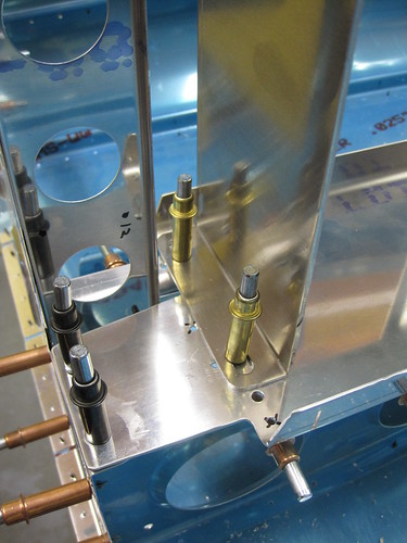
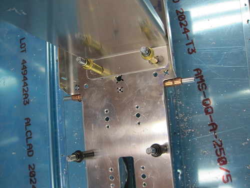
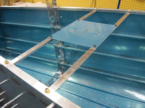
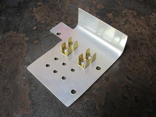
Along the same lines, I don't yet have magnetometers to mount, but I know I want to keep them far away from anything with ferrous metals in it. The all-aluminum tail cone is a great place for this, so I fabricated a little shelf in the middle of the tail cone that will hold the magnetometer(s) when I get around to choosing and buying some. All of the attachment hardware is brass so as not to affect the magnetic field in the area of the sensors. The angle-aluminum cross bars will get mounted now, the shelf will go on when the magnetometers arrive, allowing me to customize how they will be attached.
There will be a conduit running down the top center of the tail cone to service the magnetometers and the ELT antenna, and it is supported by lightening hole wire tie brackets in the F-1007 and F-1008 frames. However, these frames are somewhat far apart and I wanted additional support for the conduit, so I made a couple of little hangers that span the A and B stiffeners and have a hole in the middle for an adel clamp to be mounted. Nothing fancy.
Next up was a doubler for the ELT antenna. I decided to mount it on the top of the tail cone, just aft of the F-1008 frame and just left of the A stiffener. Unfortunately the new E-04 antenna cannot be mounted under the empennage fairing like the old E-01 one could. So this is going to be ugly... but with the added capabilities of the 406MHz satellite support, perhaps it'll actually be useful and not just a compliance checkbox... Anyway, the antenna needed a doubler. So I cut out a two inch square piece of sheet stock and drilled a circular pattern of holes in it. Then I used this as a template to match drill the holes into the top skin.
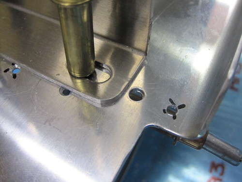
The last of the custom fabrication tasks was to cut holes for the NACA inlets on the sides of the tail cone. I made a template for the hole out of cardboard, then traced the location onto the skins I made the long axis of the intake parallel to the longerons, rather than the adjacent stiffeners. To cut out the hole, I drilled a 1/2" pilot hole at the forward end, then used a nibbler to trace the perimeter of the hole. Then I went at the edges with a file, a dremel sanding drum, and a scotch bright pad. Here's the nibbler in action:
And here's the final result:
With that done, it was (finally) time to return to the plans and continue working towards a finished tail cone. The next step says, "disassemble all parts." One lingering question remained, however, that was best answered with the tail cone still assembled. The fully-assembled tail cone is too big to fit out the door. So how much of it can I rivet together and still squeeze it out the shop door and into the garage? To test this, I took off the F-1006 bulkhead as it is clearly too large to fit through my door in any orientation. I also moved all of the aft clecos from the bottom skin to the inside of the tail cone, thus minimizing the total height of the piece (it is less tall than it is wide, so I'll try to move it out the door on its side).
In this configuration, my friend Mike and I were just able to get it out the door with about 1/4" to spare on either side. This is great news, since I will be able to do almost all of the tail cone riveting in the shop, only having to move into the garage to do the top aft skin. So I went ahead and moved what you see above into the garage and then started harvesting pieces off of it for the deburring/dimpling/countersinking phase of the process. I'm really not looking forward to the 10,000 or so hole deburrs that I need to do here (~2500 holes, each one joins at least two pieces, each hole in each piece has two sides...), but it is great to be back on the plans and making forward progress again. I managed to move several of the smaller parts onto the pile of things ready to primed (finally, some color changes in the monthly progress image!).
22 May 2010
Up until today, just little bits of deburring and dimpling has been going on every now and then. Now I have a live-inslave labor summer student who agreed to help with some of the
dull deburring tasks, so today we set about making a dent in the sizeable deburring requirements
of the tail cone.
At this point all of the small parts of the tail cone are done per the plans up the point of priming. All of the stiffeners except for the two F stiffeners are also ready for primer (the F pair need some modifications due my cutting them short awhile back). All frames and bulkheads are now ready for primer as well (with the exception of a few custom holes I'm going to drill for lightening hole tie-down brackets and adel clamps). This leaves only the skins to deal with.
Today we managed to knock out all of the deburring and dimpling on both top skins and the right side skin. Here is a shot of the completed forward top skin:
And here is the aft top skin:
You can see in this picture where I am installing the doubler for the ELT antenna. It is just aft of the left-side B stiffener. I made a 2" circle of holes where rivets will join the doubler to the skin. A pilot center hole is also present, though it will eventually be widened to accomodate the antenna's connector.
Here is a picture of the side skin all dimpled up, along with one of my cats:
Through some careful planning and a lot of rotating the part around, Jeremy and I were able to do all of the holes in the side skin with the DRDT-2 dimpler except the 20 or so holes that are located on the radiused bend. These I did one by one with the pop riveter and its associated dimple die set. Takes about an order of magnitude longer per hole, but given how few of them there were it wasn't a problem.
Hopefully tomorrow I can knock out the other side skin and start doing some of the remaining work that is required on the bottom skins and F-stiffeners. Once those are done, it'll be time for chemistry once again! And then, the fun part. Riveting.
23 May 2010
Spent all day today working on the plane, trying to push through the remainder of the deburring and dimpling ennui.
Knocked out the left side skin in the morning without any problems.
This left only the F-stiffeners and the bottom skin remaining in my pile of incomplete stock parts. As you'll recall from way back when I started the tail cone, I biffed the cuts on the F stiffeners and made them both too short by about an inch. Rather than re-order the parts and start over, I decided to just fashion some extenders for the stiffeners. I cut off another three inches from each one, then made an extension of each so that the two parts laid end-to-end would be the same length as the original stiffener was meant to be.
Next, I laid another piece of stiffener stock over both parts, match drilled all of the holes through the stiffeners and skins, and added some additional holes through the flanges of the stiffener stock so that the three pieces were held together firmly in two dimensions.
Next on the hit parade, I made a doubler plate for a possible future NAV antenna on the underside of the aft end of the tail cone. This essentially just like the one Tim Olson put on his plane. When I decide to outfit the plane for IFR, this will be a great out-of-the-way spot for a good VOR/LOC/GS antenna.
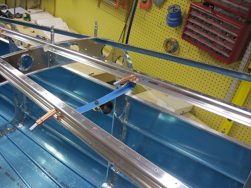
Next up was cable and conduit management hardware. I added a lot of holes for adel clamps and lightening hole wire tie anchors. Here is a shot of the hardware for bringing the top-side aft tail cone electronics (vertical stabilizer cable bundle and elevator trim servo bundle) down and across to where the bottom conduit will terminate:
Here's another shot showing the hardware that will manage the static air lines and the terminus of the upper conduit:
I had been spending a lot of time trying to figure out how to attach my forest-of-tabs grounding block to my grounding plate near the battery. There wasn't a lot of room because I only had the idea to add tabs here after I had fabricated the plate and drilled a bunch of holes in it. What I ended up with was attaching the tabs to the plate via CS4-4 countersunk blind rivets from the bottom side. I countersunk four big holes into the bottom of the plate for this purpose:
And here's what the tabs will look like after I rivet them on (I'm waiting until the part is Alodined before I rivet the brass on):
With that out of the way, I was done with drilling ops for the day and went back to deburring and dimpling. The only piece left was the bottom tail cone skin. I made quick work of it:
You can see af the narrow end where the circle of rivets is that will secure the NAV antenna doubler. The hole in the center is just a pilot hole and will eventually be enlared to support an antenna.
The last thing I did today was attach three Click Bond threaded studs to the bottom skin. These are for attaching adel clamps that will support the bottom conduit between frames and bulkheads. I'm really impressed with how easy these parts are to attach and how strong the adhesive seems to be.

The only things on my TODO list before I can start the alumiprep/alodine/akzo chemistry funtime are:
5 Jun 2010
I finally got around to the small ProSeal tasks that were holding me up. This morning I scuffed and cleaned the second side skin, placed some cardboard underneath both side skins, mixed up my little tiny bottle of ProSeal, and glued on the static ports and the NACA intakes. Here is a picture of one of the NACA intakes glued and cleco'd to the side skin, with a hand drill sitting on it to add some pressure:
And here is a bad picture of one of the static ports glued in place, held down by a couple of squeezer yokes. Note that I already attached the initial right-angle fittings:
Even those these tasks only took me about an hour total, I had for some reason put them off for the last two weeks because I felt like I wouldn't have enough ProSeal or maybe that I wouldn't have enough space to do both sides at once (and I only had one little bottle of ProSeal). With the sealant curing now, and needing a few days to get fully cured up, I can't proceed with much because the skins are covering both of my workbenches.
One thing I could make forward progress on was doing the Alumiprep and Alodine treatments of the smaller tail cone parts which could be dunked in the storage buckets for the chemicals.
I noticed that none of the parts got nearly as "golden" as in previous Alodine sessions. I'm wondering if it has a shelf life or something that I don't know about. The parts are slightly yellowed, but nothing like what I got before. The Alumiprep is definitely still working, bubbling like crazy and lifting off all of my sharpee markings.
13 Jun 2010
The ProSeal is done curing now. Here's what the static air ports look like:
And here is what the NACA intakes look like from the inside:
With the alodining done on the grounding plate, I went ahead and riveted on some grounding tabs:
However, as you can see from this picture, the Alodine just didn't take very well. The word on the street is that my batch has just used up most of its Cromium or something, leaving it ineffective. So I went ahead and bought another gallon of Alodine and I will re-do the small parts when I do the larger parts next week. Unfortunately, my timing on ordering the Alodine was poor and it doesn't arrive until Monday, so this weekend will be spent waiting instead of working.
Continue on to part 3 of the tail cone construction log.
25 Mar 2010
It's been awhile! I've been out of the country for three weeks, so there hasn't been a lot going on with the plane. I did manage to do one small modification before I left; I enlarged the cutouts in the frames where the longeron passes through so that they weren't rubbing against each other anymore and the frame flange was able to press up flush against the skin like it should. Did the enlarging with a dremel reamer bit.
Also, before I left, I put in some major orders for tail cone accessories. Stuff that isn't part of the plans but that I need to figure out the mounting logistics for before I prime the tail cone parts. The most significant accessory is the built-in oxygen system. I went with a CFFC-048 tank which holds 48 cubic feed of oxygen, a pneumatically controlled regulator, an electronic pressure transducer and associated 1.5" panel gauge, and a refill station with integrated pressure readout. Here is the tank:
And here's where I'm planning to mount it (roughly). I'll be building a little platform for it to bolt down to which will attach to the J-stiffeners on the bottom skin.
In addition to the oxygen system, I also got the parts for my external power subsystem. This includes the jack itself, a contactor, a pull breaker, a large LED to indicate contactor status, some polarity protection diodes, and a crowbar overvoltage protection module. Shown below is everything except the crowbar and the diodes.
I also got a battery box made specifically for the Odyssey 925 battery I intend to use. It will bolt down onto the battery tray as seen below:
See the tail cone photo gallery to see pictures of the bits not shown here, including the PCR, the oxygen fill port, the pressure gauge, some of the oxygen plumbing hardware, and the main battery hot bus fuse block.
Last night I got started on the elevator trim servo wiring though I didn't get very far. I put some heat shrink over the wire bundle and crimped pins on to the 26AWG wires for later insertion into a CPC. I don't have my own heat gun, so I ordered one and I'm waiting on it to arrive before I can shrink the tubing.
I still need to fabricate a drop plate on the flange of the elevator trim bracket to hold the CPC and possibly order a strain relief device for the back side of the CPC, though I may just go with some RTV.
So not a lot of work on the plane in the last month, but lots of new bits and pieces to start mounting!
1 Apr 2010
No, it's no April Fool's joke, I actually found time to do more work on the plane!
I spent a lot of time while I was out of the country doing some planning for the tail cone accessories and the steps required to install each. Tonight I put those steps in a sensible order, and drew a line on each list at the point where I would need to disassemble the tail cone before continuing. Everything above that line is now on the critical path. This evening I spent some time getting the elevator trim servo bracket assembly and static air system lists down to the disassembly-required line.
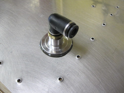
First, I fabricated a small bracket that sits aft of the rivet line that attaches the two halves of the frame that sits just aft of the static airports. This bracket will support the T-junction that joins the two sides of the static air system. Here it is cleco'd to the frame:
I discovered that if I put the 90° elbows coming right off the static ports facing aft, they poke right through the lightening holes in the frame. This allows me to plumb all of the static line and associated clamp hardware to the aft of the frame. This, in turn, keeps all of it out of the way of the skin rivets associated with the frame, which are all on the front side. That means that I can go ahead and run the static lines up as far as the T junction before riveting on the top skin, preventing me from having to crawl inside the dark enclosed tail cone to do it later. Here is a picture of the T-junction temporarily installed on its bracket:
Next, I fabricated a little drop plate to hang off the side of the elevator trim servo bracket. It holds a panel-mount circular plastic connector for the five servo control and sense wires.
With it fabricated, the elevator trim servo bracket parts are all ready for priming. One more small modification regarding elevator trim was to add a hole in the aft deck for an Adel clamp on the bottom face of the deck. This clamp will be the last support for the cable that will eventually connect to to the CPC in the drop plate.
The only other thing I did tonight was to mark some hole positions on the F-1028 channel for Adel clamps that will hold the top conduit on one side and the wire bundle coming out of the overhead console on the other. After marking the holes, this section was ready for disassembly as well and was moved off the critical path list.
Accessory assemblies still on the list of things to do before disassembly:
- Top wiring conduit
- Bottom wiring conduit
- Airframe grounding bracket
- Main battery box
- Main battery contactor
- External power contactor
- Magnetometer shelf
- Oxygen tank
- Oxygen distribution manifold
- ELT
- ELT antenna
- NACA ventilation inlets
4 Apr 2010
Did a short stint of work today on the Odyssey PC925 battery box. This part replaces the two battery tray side bars, the hold-down bar, and the two hold-down bolts of the RV-10 kit. Unfotunately, it doesn't match the hole pattern for the kit's side bars. I went ahead and lined up one hole (the front right one) just to save work. This kept the right-side holes aligned over the rib rail beneath the battery tray for support. However, the left-side holes were well inside of the left rib rail so they'll have less support. I started off by drilling a new #12 hole for the front-left battery box hole, then adding countersunk rivet holes for a K1000-3 nutplate on the bottom of the batter tray.
The forward-left corner becomes problematic. What was originally the forward-left hole for the battery tray side bar is now unused. But it is the only thing nearby that secures the battery tray to the rib rail underneath. So I'd really like to just put a bolt in there anyway. However, the hole is too close to the edge of the battery box to accept a bolt head.
I thought about making a shim that is the same thickness as the battery box flange and then bolting that down, but I think instead I'll just make part of the airframe ground bracket (which will eventually be attached in the blank area of the battery tray just forward of the battery box) stick out over this spot and act as a shim. Either way, both the new and the old battery hold-down holes will have bolts in them.
Turning to the aft end of the battery box, we have even more problems.
First, the aft-left hole required a new set of nutplate holes which are also not supported by the rib rail. Again, the existing hole is now too close to the box to accept a bolt directly (though in this case filing down the corner of the box may suffice). The bigger problem is on the aft-right side, where the new hole through the battery tray and the rib rail beneath is too close to the existing nutplate rivet hole for the old side bar hole.
I'll have to add a nutplate for this hole that only has one lug, and I don't have any of those in the correct size. So that bit is on hold awaiting more parts.
Actually, everything is now on hold awaiting more parts. I spent a bit of time this evening thinking about exactly what I need to finish all of the accessories mounting in the tail cone, and came up with a big list of hardware, tools, and parts that I needed to buy. $180 later, I'm now on hold. And it probably won't arrive before I'm off galavanting around the world again next week. So this may be the sum total of the work that gets done on the plane in April. Oh well... slow progress is still progress.
4 May 2010
Out of the country for another three weeks there, now I'm back with a powerful case of jetlag. Didn't want to engage in anything too complex since my brain is still somewhere over eastern Europe, so I spent some time (between three and five in the morning) fabricating the airframe ground bracket.
The wiring harness plans (OP-37?) call for putting a bolt through this piece of the battery tray and attaching a 2 AWG wire from the battery ground terminal to the bolt, thus connecting the airframe to the electrical ground system. This allows things like lights and pitot heat to be connected to ground locally rather than having to run heavy ground wires around for these high-current sources. However, because of all the accessories I'm loading into the tail cone, in particular the external power socket, I need quite a few grounds to come together here. The two coming from the external power socket and the battery are both 2 AWG, and I didn't want to try to load all of that onto one bolt.
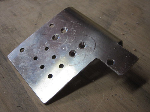
In addition, I wanted the grounding bolts to be mounted horizontally rather than the suggested vertical arrangement, which I think will make my wiring look a little cleaner in this area. I have seen other builders put a piece of aluminum angle here and bolt into that, so I started designing something like that. Another design goal of mine was to be able to use the original forward-left battery hold-down bolt hole to help with the new battery box. As you can see from the photo, above, the old hole is right up against the edge of the battery box, so I wouldn't be able to fit a washer on there. I considered grinding down some washers to fit that space, but instead decided to just extend the grounding bracket to include a tab that sticks out into this space. Using metal of the same thickness, I can now put a washer and bolt into that hole and it would clamp down the box and take advantage of the rib rail beneath the original hole (the new hole just has the tray and no support underneath). With this in mind, I cut out a piece of 0.063" aluminum (the closest sheet thickness I could find to the thickness of the battery box) that looks like this:
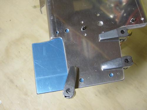
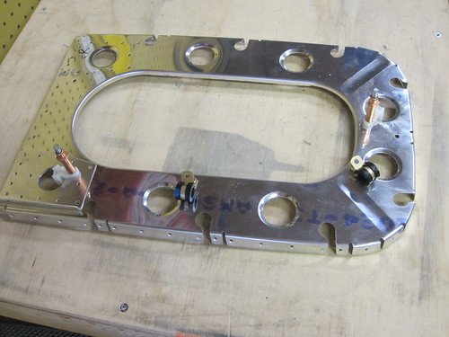
The wide tab on the left side (right in this image) will get bent upwards and the grounding bolts will attach to this. Looking at the bottom of the battery tray with the new piece clamped in place, you can see the three bolt holes that they share:
The small hole in the upper-left of this photo will not be used and thus will not be match-drilled into the grounding bracket. The two holes at the bottom of the photo are for the bolts that attach the battery tray to the F-1006 frame. After match-drilling these three bolt holes, the bracket looks like this:
Because the battery tray must be removable from the completed plane in order to allow maintenance on the elevator pushrod system, there can be no rivets that attach the tray to any of the other stock airframe. I wanted to rivet the grounding bracket to the tray, however, to increase the electrical connectivity between the two. To achieve this, I drilled six holes between the two parts for 1/8" rivets in a spot that was clear of the underlaying rib rail and F-1006 tab. I also used a hand-seamer to put a 90° bend in the bracket to match the adjacent flange on the battery tray.
Most of the grounding bracket won't get primed so that there is a good electrical connection between the bolt heads and the bracket. Before priming the rest of the battery tray (but after alodining both parts), I will rivet these six holes with AN470 hardware. Then I'll mask the parts that don't get primer and spray it down.
The next task was to drill some holes for anchor nuts that would hold the actual grounding bolts, but I had a brain wave at the last moment that caused me to change my design a bit. I was thinking of two large AN4 bolts for the battery and external power connector 2 AWG lines, pluse a third AN3 bolt for the assorted low-current ground returns that come here (overhead console lighting, external power relay control, etc.). However, having a bunch of wires returning to a threaded post like that, each with its own ring termianl, is going to get ugly fast. Instead, why not use a small "forest of tabs" style grounding buss attached right to the bracket. SteinAir sells a nice 10-tab version that is only a couple inches long. I've got one on order now, and when it arrives I'll figure out a way to attach it to the base of the grounding bracket, then I can route up to 10 small-gauge grounding wires here cleanly. Until it arrives, this piece is on standby.
6 May 2010
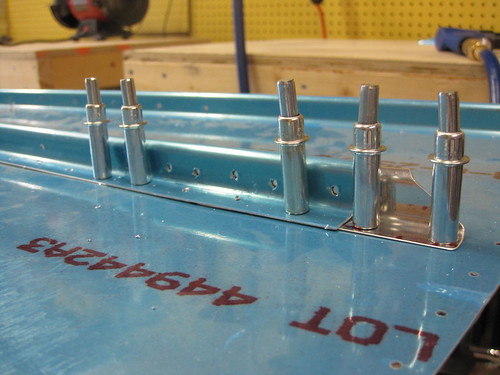
Today I knocked out most of the oxygen tank mount hardware. I had been planning to put the tank on the left-side wall, attaching it to the D and E stiffeners. However, I noticed that the documentation for the tank clamps indicates that it supports considerably less side-loading than it does up-and-down loading. And since the highest forces likely to be encountered are landing shocks (oriented in the vertical axis), I wanted to orient the tank such that the clamp feet were on the bottom (or top...) of the tank. As a result, I moved my design to the work with the outer two J-stiffeners on the left side of the bottom skin of the tail cone, in the bay between the F-1006 and F-1007 frames.
The first step was to fabricate two 14" lengths of 1.5" x 2" x 0.125" angle aluminum. The reason I used such a large angle was because the stiffeners aren't parallel. Thus, if I align the feet with an edge on one angle bracket, the feet will be skewed on the other and require a larger landing. I drilled seven holes, every two inches, a quarter inch above the edge of the shorter side of each angle. Then I used my right-angle drill kit to match-drill these holes into the J-stiffener flanges.
When I cleco'd the angle brackets into place, I could see that the J-stiffener flanges were not perpendicular to the bottom skin. As a result, the two "horizontal" parts were not co-planar.
This wasn't a big problem, because a gentle push on the horizontal parts would bend the stiffener flange slightly and result in good alignment between the two brackets. I decided to fashion a plate to connect the two angle brackets and ensure that they were laying co-planar. This worked like a charm and didn't impose too much stress on the J-stiffeners.
I added a series of twelve 1/8" holes for eventual rivets between the top plate and the angle brackets. From here, it was simply a matter of match-drilling the feet of the oxygen tank clamp into the angle brackets and top plate. Eight 1/4" holes later, the tank could be bolted onto to the brackets.
In the picture above, the bolts are just stuck through the holes with no nuts or anything. Also, they are all different lengths because I haven't bought hardware for this yet. My plan is to put K1000-4 nutplates on the underside of the angle brackets to capture the eight bolts. AN4-5A bolts should be perfect.
Technically, with the clamp feet bolted into the nutplates, the twelve rivet holes become redundant. Also, once rivets are put in place there, the top plate is no longer removable. On the off chance that I decide to run some wires underneath this assembly and want to attach an adel clamp to the bottom side of the top plate, I will probably leave these rivet holes empty at least until wiring is complete, if not forever. They were just there to hold everything square with clecos while I drilled out the bolt holes.
9 May 2010
Big day today, culminating with the long-awaited return to following the plans after having finished fabrication tasks for the custom accessories.
First up was to match-drill a mounting bracket for the ELT into the right-side stiffeners. This was a quick job. I don't have the ELT yet (it is still on backorder and has been for many months), but when I get it I can just figure out how to get its quick-release plate mounted to this bracket. Mounting the bracket to the plane is just a matter of eight blind rivets. Now that the holes are matched drilled, the ELT mounting task can be put off essentially indefinitely without affecting the critical path.
Along the same lines, I don't yet have magnetometers to mount, but I know I want to keep them far away from anything with ferrous metals in it. The all-aluminum tail cone is a great place for this, so I fabricated a little shelf in the middle of the tail cone that will hold the magnetometer(s) when I get around to choosing and buying some. All of the attachment hardware is brass so as not to affect the magnetic field in the area of the sensors. The angle-aluminum cross bars will get mounted now, the shelf will go on when the magnetometers arrive, allowing me to customize how they will be attached.
There will be a conduit running down the top center of the tail cone to service the magnetometers and the ELT antenna, and it is supported by lightening hole wire tie brackets in the F-1007 and F-1008 frames. However, these frames are somewhat far apart and I wanted additional support for the conduit, so I made a couple of little hangers that span the A and B stiffeners and have a hole in the middle for an adel clamp to be mounted. Nothing fancy.
Next up was a doubler for the ELT antenna. I decided to mount it on the top of the tail cone, just aft of the F-1008 frame and just left of the A stiffener. Unfortunately the new E-04 antenna cannot be mounted under the empennage fairing like the old E-01 one could. So this is going to be ugly... but with the added capabilities of the 406MHz satellite support, perhaps it'll actually be useful and not just a compliance checkbox... Anyway, the antenna needed a doubler. So I cut out a two inch square piece of sheet stock and drilled a circular pattern of holes in it. Then I used this as a template to match drill the holes into the top skin.
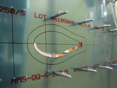
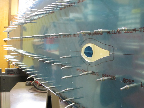
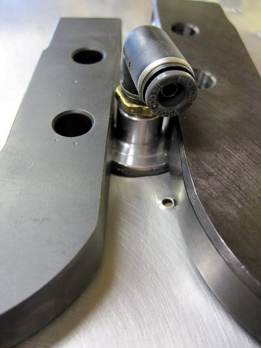
The last of the custom fabrication tasks was to cut holes for the NACA inlets on the sides of the tail cone. I made a template for the hole out of cardboard, then traced the location onto the skins I made the long axis of the intake parallel to the longerons, rather than the adjacent stiffeners. To cut out the hole, I drilled a 1/2" pilot hole at the forward end, then used a nibbler to trace the perimeter of the hole. Then I went at the edges with a file, a dremel sanding drum, and a scotch bright pad. Here's the nibbler in action:
And here's the final result:
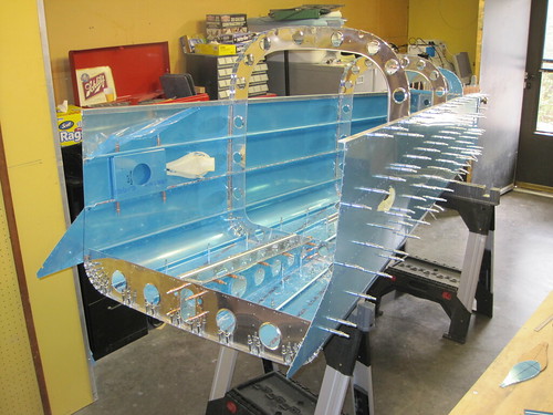
With that done, it was (finally) time to return to the plans and continue working towards a finished tail cone. The next step says, "disassemble all parts." One lingering question remained, however, that was best answered with the tail cone still assembled. The fully-assembled tail cone is too big to fit out the door. So how much of it can I rivet together and still squeeze it out the shop door and into the garage? To test this, I took off the F-1006 bulkhead as it is clearly too large to fit through my door in any orientation. I also moved all of the aft clecos from the bottom skin to the inside of the tail cone, thus minimizing the total height of the piece (it is less tall than it is wide, so I'll try to move it out the door on its side).
In this configuration, my friend Mike and I were just able to get it out the door with about 1/4" to spare on either side. This is great news, since I will be able to do almost all of the tail cone riveting in the shop, only having to move into the garage to do the top aft skin. So I went ahead and moved what you see above into the garage and then started harvesting pieces off of it for the deburring/dimpling/countersinking phase of the process. I'm really not looking forward to the 10,000 or so hole deburrs that I need to do here (~2500 holes, each one joins at least two pieces, each hole in each piece has two sides...), but it is great to be back on the plans and making forward progress again. I managed to move several of the smaller parts onto the pile of things ready to primed (finally, some color changes in the monthly progress image!).
22 May 2010
Up until today, just little bits of deburring and dimpling has been going on every now and then. Now I have a live-in
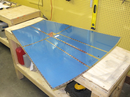
At this point all of the small parts of the tail cone are done per the plans up the point of priming. All of the stiffeners except for the two F stiffeners are also ready for primer (the F pair need some modifications due my cutting them short awhile back). All frames and bulkheads are now ready for primer as well (with the exception of a few custom holes I'm going to drill for lightening hole tie-down brackets and adel clamps). This leaves only the skins to deal with.
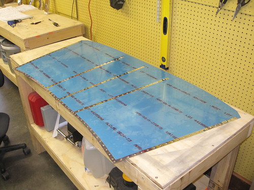
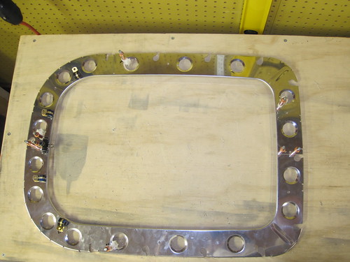
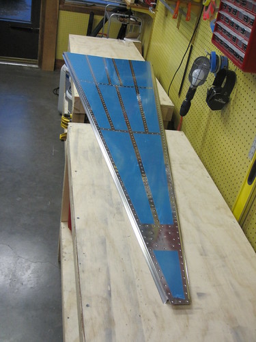
Today we managed to knock out all of the deburring and dimpling on both top skins and the right side skin. Here is a shot of the completed forward top skin:
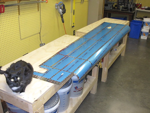
And here is the aft top skin:
You can see in this picture where I am installing the doubler for the ELT antenna. It is just aft of the left-side B stiffener. I made a 2" circle of holes where rivets will join the doubler to the skin. A pilot center hole is also present, though it will eventually be widened to accomodate the antenna's connector.
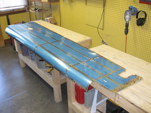
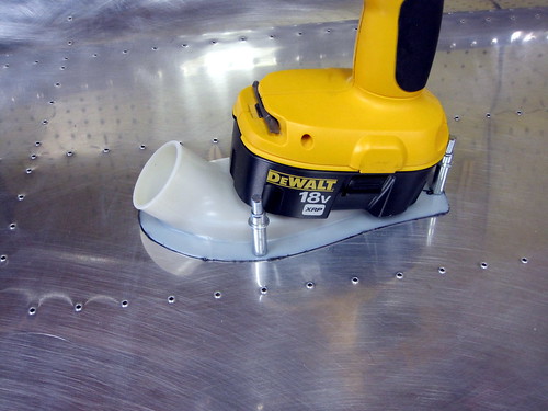
Here is a picture of the side skin all dimpled up, along with one of my cats:
Through some careful planning and a lot of rotating the part around, Jeremy and I were able to do all of the holes in the side skin with the DRDT-2 dimpler except the 20 or so holes that are located on the radiused bend. These I did one by one with the pop riveter and its associated dimple die set. Takes about an order of magnitude longer per hole, but given how few of them there were it wasn't a problem.
Hopefully tomorrow I can knock out the other side skin and start doing some of the remaining work that is required on the bottom skins and F-stiffeners. Once those are done, it'll be time for chemistry once again! And then, the fun part. Riveting.
23 May 2010
Spent all day today working on the plane, trying to push through the remainder of the deburring and dimpling ennui.
Knocked out the left side skin in the morning without any problems.
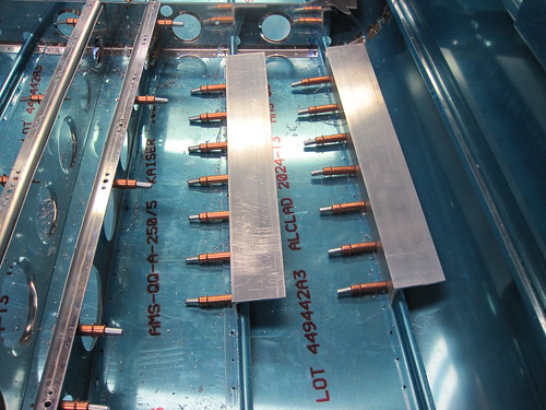
This left only the F-stiffeners and the bottom skin remaining in my pile of incomplete stock parts. As you'll recall from way back when I started the tail cone, I biffed the cuts on the F stiffeners and made them both too short by about an inch. Rather than re-order the parts and start over, I decided to just fashion some extenders for the stiffeners. I cut off another three inches from each one, then made an extension of each so that the two parts laid end-to-end would be the same length as the original stiffener was meant to be.
Next, I laid another piece of stiffener stock over both parts, match drilled all of the holes through the stiffeners and skins, and added some additional holes through the flanges of the stiffener stock so that the three pieces were held together firmly in two dimensions.
Next on the hit parade, I made a doubler plate for a possible future NAV antenna on the underside of the aft end of the tail cone. This essentially just like the one Tim Olson put on his plane. When I decide to outfit the plane for IFR, this will be a great out-of-the-way spot for a good VOR/LOC/GS antenna.
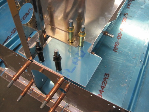
Next up was cable and conduit management hardware. I added a lot of holes for adel clamps and lightening hole wire tie anchors. Here is a shot of the hardware for bringing the top-side aft tail cone electronics (vertical stabilizer cable bundle and elevator trim servo bundle) down and across to where the bottom conduit will terminate:
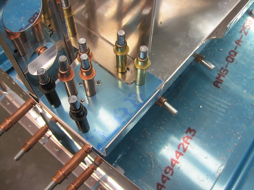
Here's another shot showing the hardware that will manage the static air lines and the terminus of the upper conduit:
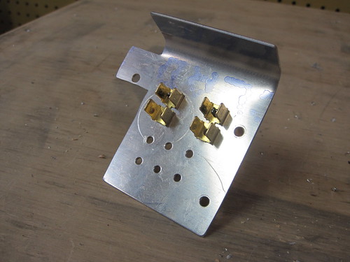
I had been spending a lot of time trying to figure out how to attach my forest-of-tabs grounding block to my grounding plate near the battery. There wasn't a lot of room because I only had the idea to add tabs here after I had fabricated the plate and drilled a bunch of holes in it. What I ended up with was attaching the tabs to the plate via CS4-4 countersunk blind rivets from the bottom side. I countersunk four big holes into the bottom of the plate for this purpose:
And here's what the tabs will look like after I rivet them on (I'm waiting until the part is Alodined before I rivet the brass on):
With that out of the way, I was done with drilling ops for the day and went back to deburring and dimpling. The only piece left was the bottom tail cone skin. I made quick work of it:
You can see af the narrow end where the circle of rivets is that will secure the NAV antenna doubler. The hole in the center is just a pilot hole and will eventually be enlared to support an antenna.
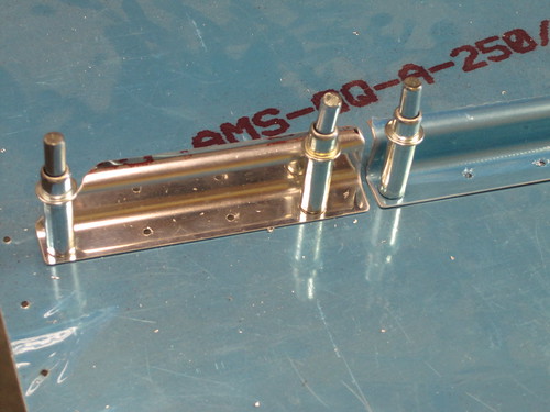
The last thing I did today was attach three Click Bond threaded studs to the bottom skin. These are for attaching adel clamps that will support the bottom conduit between frames and bulkheads. I'm really impressed with how easy these parts are to attach and how strong the adhesive seems to be.
The only things on my TODO list before I can start the alumiprep/alodine/akzo chemistry funtime are:
- Scuff and clean the inner surfaces of the skins (bottom skin already done).
- Bond the static air ports in place with ProSeal.
- Bond the NACA vents in place with ProSeal.
5 Jun 2010
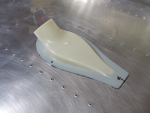
I finally got around to the small ProSeal tasks that were holding me up. This morning I scuffed and cleaned the second side skin, placed some cardboard underneath both side skins, mixed up my little tiny bottle of ProSeal, and glued on the static ports and the NACA intakes. Here is a picture of one of the NACA intakes glued and cleco'd to the side skin, with a hand drill sitting on it to add some pressure:
And here is a bad picture of one of the static ports glued in place, held down by a couple of squeezer yokes. Note that I already attached the initial right-angle fittings:
Even those these tasks only took me about an hour total, I had for some reason put them off for the last two weeks because I felt like I wouldn't have enough ProSeal or maybe that I wouldn't have enough space to do both sides at once (and I only had one little bottle of ProSeal). With the sealant curing now, and needing a few days to get fully cured up, I can't proceed with much because the skins are covering both of my workbenches.
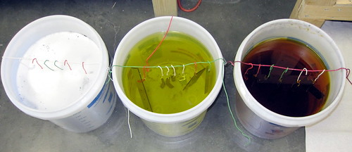
One thing I could make forward progress on was doing the Alumiprep and Alodine treatments of the smaller tail cone parts which could be dunked in the storage buckets for the chemicals.
I noticed that none of the parts got nearly as "golden" as in previous Alodine sessions. I'm wondering if it has a shelf life or something that I don't know about. The parts are slightly yellowed, but nothing like what I got before. The Alumiprep is definitely still working, bubbling like crazy and lifting off all of my sharpee markings.
13 Jun 2010
The ProSeal is done curing now. Here's what the static air ports look like:
And here is what the NACA intakes look like from the inside:
With the alodining done on the grounding plate, I went ahead and riveted on some grounding tabs:
However, as you can see from this picture, the Alodine just didn't take very well. The word on the street is that my batch has just used up most of its Cromium or something, leaving it ineffective. So I went ahead and bought another gallon of Alodine and I will re-do the small parts when I do the larger parts next week. Unfortunately, my timing on ordering the Alodine was poor and it doesn't arrive until Monday, so this weekend will be spent waiting instead of working.
Continue on to part 3 of the tail cone construction log.