
| Workshop | Empennage | Wings | Fuselage | Contact |
Outboard Leading Edge Construction
Current status: Under construction.
Time invested on this sub-assembly: 57 hours (46 by me)
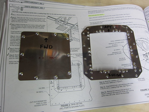
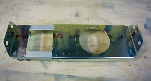
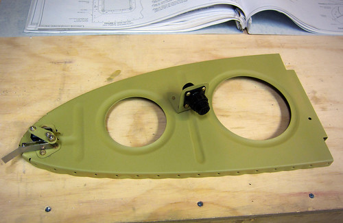
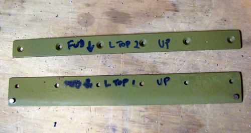
I've been doing a bit of work getting started on the leading edges. Most of it is not terribly photogenic. But just so I'll have something, here's a shot of the two plates that make up the stall warning mechanism bracket:
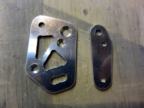
I had done most of the fab work on these two pieces awhile back, but the smaller holes call for a #31 drill, which I didn't have and wasn't available at the local hardware or home stores. So I finally, this weekend, went down to Harbor Freight and picked up an indexed drill set with #1-#60, A-Z, and all the fractionals up to 1/2" for $14. Nice. Now when these weird-sized holes that only exist once in the whole plane show up, I'll have a (low-quality) drill bit ready.
Anyway, now these two pieces are ready for priming. When the time comes, I'll be able to complete the leading-edge portions of Chapter 19 of the plans (stall warning) while the internal space where they go is still easy to access, rather than having to reach through the access hole on the bottom of the wing to adjust this mechanism.
In addition to these two tiny parts, I did manage to get all of the leading edge ribs fluted and the J-stiffeners cut to length. The four ribs that get their aft flanges modified have also been snipped. No pics of this.
The next step was to build the cradle, and I was procrastinating on this for a few reasons. For starters, I didn't have a jigsaw with which to cut out the templates on the lid of the shipping crate. This problem has been rectified. Next, when I opened the shipping crate, the lid cracked about 6" in one spot that just happened to pass right through the thinnest part of one of the leading edge cradle templates. Great. Tonight, I cut out the templates and predictably the one with the crack snapped in two almost immediately.
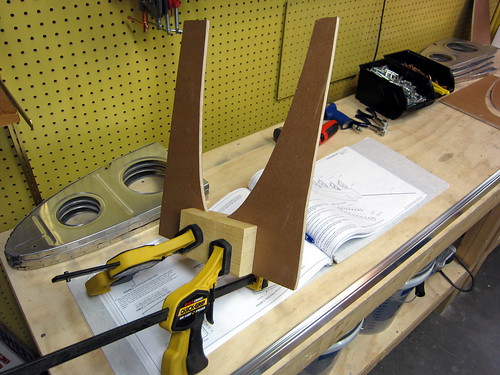
Luckily, the way it cracked left a large surface area onto which I applied wood glue and clamped the two halves back together. If this doesn't prove strong enough (I think it will), I'll just screw a backing board onto the bottom edge of this one.
18 Dec 2010
Yesterday it snowed so much that work called a snow day, and today the clouds were still low so my planned flying excursion was cancelled. Instead, I got a bunch of work done on the leading edges. First, I found a couple of old 2x4's in the garage and used them to build the side rails for the leading edge cradle. Then I took a die grinder to the fuel tank skins to separate the skin splice strip. Next, I put a small Scotchbrite wheel on the die grinder and dressed all of the edges on all parts (except the right-side leading edge skin, which hasn't been taken out of the garage yet).
With all of that preparatory work out of the way, it was finally time to do the initial assembly on the left-side leading edge.
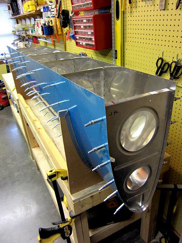
The only issue with the new cradle was that the two old 2x4s were really warped, so to get it to lay flat I had to clamp it to the table. Getting the holes to line up between the skin and the ribs was a challenge. And even with all of the holes cleco'd, I couldn't get the forward most holes to line up on any of the ribs. Not sure what to do about that yet.
I proceeded with the J-stiffener, which was exactly the right length. The centerline I had previously drawn on it stayed perfectly aligned in the skin holes without any work from me, so this should be considerably easy to work with than the tail cone J-stiffeners (which I had to manhandle to get to line up right). My dad, who is visiting for the week, helped me dril out the holes between stiffener and skin.
The last piece to go on was the skin splice strip, and this was the most difficult piece of the whole assembly. It is wedged between the inboard rib and the skin, which means that the holes in three pieces have to line up before the cleco has any chance of going through. Again, there were a few holes at the forward end that I couldn't get to line up at all. They're close enough that I think I can just match drill them and they'll be essentially round.
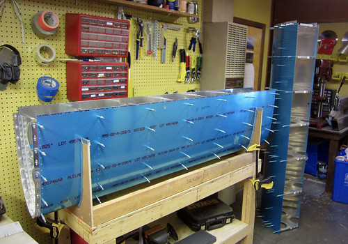
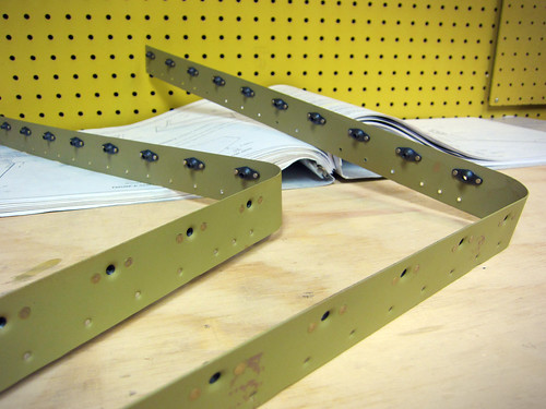
This is all ten parts that make up the leading edge assembly per the plans; the next step is to match drill all of the skin holes. I'm awaiting delivery of the landing light kits from Duckworks so that they can be installed before finalizing the leading edge assembly. I'll also be doing some of the stall warning modifications prior to priming these parts. And, of course, there's always the right-side leading edge to contend with as well.
25 Dec 2010
I spent some time over the last couple days doing little bits and pieces for the leading edges. On the left side, I got the stall warning access hatch doubler match drilled.
With that done, I remved it and cut off the two alignment tabs. Then I drilled the four corner holes for the hatch cutout in the skin.
I don't have a fine-tooth blade for my jigsaw meant for cutting thin metal like this, so I'll have to wait on finishing the hatch hole. Instead, I finished off the hatch cover itself and the doubler by deburring all holes and dimpling.
These two parts are now ready for alodining and priming. The next small task I took care of was the stall warning vane slot. This starts as just two small 3/32 holes in the skin which I enlared to #10, then filed out the material between the holes.
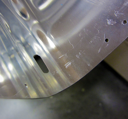
I'm really happy with how clean this hole came out, especially for being hand-carved with a small jeweler's file.
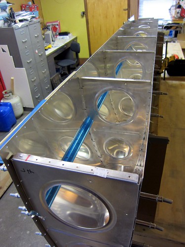
I set aside the left leading edge and put the right side leading edge together remarkably quick. Both assemblies are now complete per the plans up through the step where they are to be fully disassembled so that the deburring and dimpling phase can begin.
However, there are a couple of customizations I want to build in before I disassemble anything. The first is a CPC connector in the inboard bay on the left side. This will service the stall warning switch as well as any accessory I might eventually wire into this bay. The most likely candidate here would be a down-firing camera attached to the access hatch cover. I'm not planning on building that in initially, but I like to keep my options open. Running a few extra wires and adding a CPC will make adding such a thing really easy in the future.
The other customization for the leading edges is the inclusion of Duckworks Aviation leading edge PAR-36 landing light mounts. I haven't decided if I'm going to go with HID lamps or shell out for the (very expensive) LED lamps, so for now I'm just going to install the mount brackets. I've already ordered them but they are taking their time getting to me. I want to install those while everything is still fully assembled, so I'm putting the leading edges on hold until the Duckworks parts arrive.
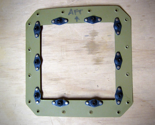
One last get-ahead task I did before moving the leading edges to the garage was to take out the splice strips and do the dimpling and countersinking for the nutplates. Reinstalled the splice strips for storage. The results can be seen in the image above if you zoom in.
28 Dec 2010
The Duckworks Aviation leading edge landing light kits showed up last night, so this morning I started a bit of work on them.
The first step was to make the template for the rib holes. This was a simple matter of glueing the included piece of paper onto some cardboard, cutting out along the line, poking the two holes through the cardboard, then marking the ribs through the holes.
Once the center holes are marked, they are drilled out to accept #10 bolts and then the nutplate attachment holes are added using a nutplate as a template.
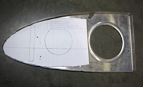
I got both of the ribs for the right wing modified in this way, then re-assembled them into the leading edge for the next step. This was to cut out the lens hole template and tape it onto the skin.
Again, the kit makes it very easy; no special measurements were required and it took very little time to get everything aligned properly. With the template in place, I just traced around the open hole with a thin sharpee and then removed the template. The next step is to cut out the traced line, either with a jigsaw or snips. I decided that snips end up bending the metal too much so I'm going to try a jigsaw, but for that I need a finer blade than I have so this step will have to wait. I did, however, drill a big 3/4" pilot hole in the center using a unibit.
It was a bit nerve racking putting a big hole in the skin of the airplane that isn't in the plans, but this isn't the first time I've done this sort of thing and this product has a strong pedigree in the RV-10 community so I'm not too worried about it.
Now I'm off to Harbor Freight to find a good thin metal jigsaw blade.
29 Dec 2010
Got a bunch of work done on the right-side landing light assembly today. Started the day down in Albuqureque, so after dropping Nina off at the airport, I swung by Harbor Freight and picked up a pneumatic body saw and some fine 32tpi metal cutting blades. This was the tool I was missing to be able to make the landing light lens cutouts in the leading edges.
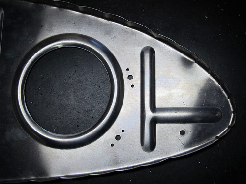
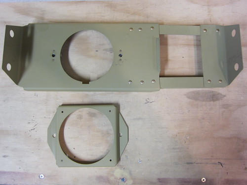
It took awhile to get it cut and dressed nicely, but in the end it looks really good. With the hole made, I started in on the light bracket itself. This involves separating the two sides of the bracket from each other, then fabricating a couple of angle bars to connect them. Here's a shot of the four pieces cleco'd together:
...and here's a shot of it test-fitted into the leading edge (as seen from aft):
Everything looked good in the test fit, so I deburred all the holes and got the nutplate attachment holes dimpled. Now all parts of that bracket are ready for surface treatment and priming.
Moving on to the lens retaining brackets. I got the top side pieces ready for priming without much difficulty. The countersinking of the really thin piece was a bit ugly, and to be honest I'm not sure why they don't just use a AD470 rivet there instead of the flush one, since the machine head of the rivet sticks out into free space inside the leading edge anyway... Regardless, those two pieces are also on the ready-for-priming pile. Here's a shot of the thin piece just after I finished match-drilling it to the skin:
I started to do the bottom retainer, but the instructions had some serious problems here and I couldn't continue without clarification. For starters, they state that the corner holes and rivets aren't used, so don't put the rivets in. The pictures all show the rivets; the piece they sent me doesn't even have the holes. I'm going to assume the verbage is correct on this one and that the photos are out of date (as it states). However, then it says to line the bottom strip up with the bottom edge of the hole, unlike in the picture (ok, fine). And it follows that up with a statement to do it just like it was done for the top retainer (which is what the picture shows). So it is internally inconsistent. I think what they want is for the strip and hole edge to line up, like this:
But I want to make sure before I drill any more holes in the skin. So this bit is on hold until I hear back from Duckworks. It's not much of a hold-up, since all that is left is this piece and the other strip for the bottom retaininer, then everything for the landing light is ready for priming. And the lens fitting won't get done until the entire leading edge is assembled, anyway.
5 Jan 2011
I've done a lot of work over the last few days, though most of it was deburring which is super boring and not terribly photogenic.
For starters, I got a prompt reply from the Duckworks folks who informed me that the position of the piece in the last photo of the previous post was accurate, so I went ahead and finished off the two lower lens retainer brackets. I also used the body saw to cut open the stall warning access hatch cover.
The doubler fits perfectly in the opening; I had to modify a couple of the corners to make the access hatch cover fit without modifications. I'd like to be able to use a stock cover in case I ever need to replace it (or need a second one to build a camera or sensor into).
Knowing that dimpling was coming up, I went ahead and removed the vinyl lines from the rivet lines on both leading edge skins.
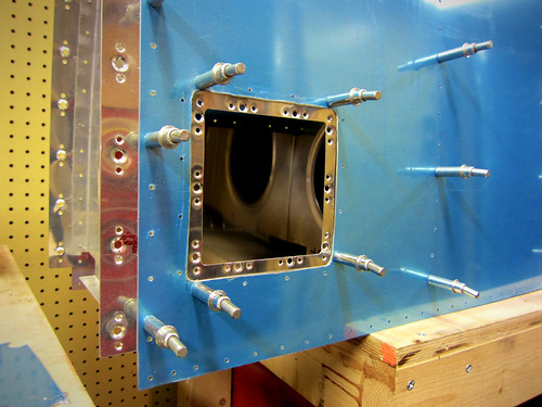
Next, I ordered and received some new Tyco/Amp circular plastic connectors. I'm going to mount one in the stall warning bay of the left leading edge. I whipped out a little bracket to hold it:
The idea here is that I can wire a full wire harness to this connector from the wing root connector in the wing. If I ever want to wire some extra sensor, camera, etc. out in the wing I can put it in this bay and only have to wire from the sensor to this connector without having to figure out how to get additional wires through the wing itself. Here's a view of where the connector is relative to the access hatch:
That concludes all of the customizations to the leading edges that needed to be fabricated before the disassembly, deburring, and dimpling could begin. I got all of the ribs in the right leading edge deburred and dimpled while I was waiting for the CPC to show up. I also got both of the skins deburred (which seemed to take forever, though in reality it was only two hours). I scuffed them up with Scotchbrite and cleaned them with acetone in preparation for priming, because this step is much easier to accomplish prior to dimpling.
This meant that the skins were ready for dimpling. But they are too unwieldy for me to do by myself. So I lured Bob and Jason from work to my house with the promise of tacos and video games in return for an hour's help dimpling skins. It was a massive success; we were able to knock both skins out quite quickly and move on to more important things like a classic Donkey Kong Tournament (winner: Jason). Sadly, no pictures of the dimpling or the results.
All that is left on the leading edges prior to priming is to debur and dimple the left-side ribs. If I can get the aileron skins dimpled and deburred and figure out how to mount the static wicks on the ailerons, I may do some priming this weekend.
17 Jan 2011
Got a bunch of little things done over the last couple weeks, but sadly there aren't a lot of pictures to show for it. For starters, I finished all of the deburring and dimpling tasks on the leading edges. Nothing really to see there; but as of yesterday they were all ready for chemistry. I also figured out where on the wingtips and ailerons I was going to mount the static wicks. The ailerons will only support a single wick each, using the second stiffener from the outboard end as a doubler. I went ahead and added nutplate holes for two anchor points to this stiffener and the skin on each side. The remaining two wicks on each wing will be in the wingtip, one right at the inboard edge, and the other a foot or so inside the tip. I'll get some pictures of the mount as I assemble the ailerons.
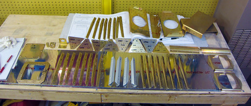
With the small tasks out of the way, it was time to do the first round of surface chemistry and priming. I got started on that today with a long haul day of Alumiprep and Alodine. I started with just the small parts that could be dunked in the chemical storage buckets.
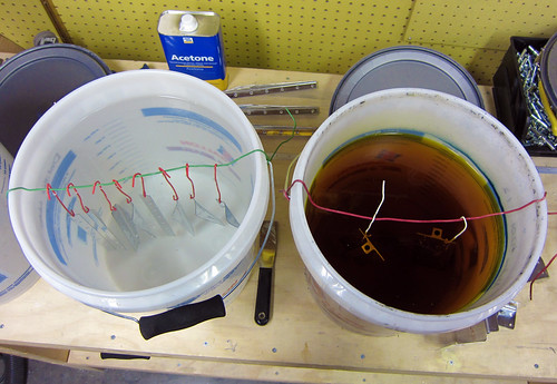
There were so many small parts (32 aileron stiffeners, 8 wing spar extension doublers, all of the landing light bracket parts, and assorted other doo-dads), that this process took me basically the entire day.
All that is left for alodine treatment are the 14 leading edge ribs, the two splice strips, and the two J-stiffeners. These are all too large to be done in the buckets, so I'll have to break out the tupperware bins (and possibly the long dunk tank for the stiffeners). This will have to wait for another day. And then I can prime.
22 Jan 2011
Priming!
I reconfigured the shop for priming and laid out all of the parts on the central table.
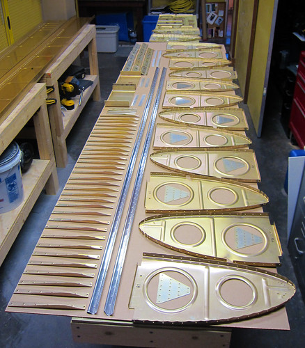
After hanging up the plastic walls, setting up the door ventillation, and waiting the 30 minutes for the freshly mixed primer to do whatever it does during the required wait, the priming itself went very quickly. I was able to do all of the non-skin pieces except the skins and the splice strips in one pass, then all of the skins except one in a second pass, then the final skin and the splice strips in a third pass.
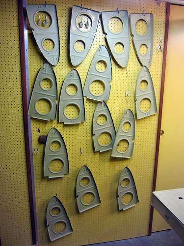
I left the parts out to dry overnight (and to de-stink the shop, which was almost intolerable with all of the aerosolized solvent all over the place). Very excited to be ready to rivet again!
23 Jan 2011
The only leading-edge related thing I did today was to put together the stall warning vane assembly, just because it was easy and quick.
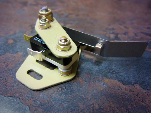
It probably won't get attached to the leading edge until the riveting of the ribs to the skin is complete, so for now it goes on the shelf.
26 Jan 2011
Preparing the right leading edge for final riveting.
Not wanting to dive into another eight hours of countersinking for the second main spar, I decided to take a break from that and do a leading edge instead. First I did the preparatory steps of adding nutplates to several pieces. First up were the splice strips:
Here's the access hatch doubler for the stall warning system. I found it odd that the nutplates hung out over the lip of it... whatever.
I also added the nutplates in the outboard two ribs which will support the Duckworks landing light brackets:

While I was at it, I went ahead and riveted together the landing light brackets themselves:
With that, all the preparatory work was done so I went ahead and set up the cradle. Assembling the 10 pieces that make up the leading edge assembly goes really fast when the skins are dimpled, there is a lot less hunting for alignment of the ribs.
I was able to do the aft-most two holes on each side of each rib with the squeezer, so I started with that. I also went ahead and squeezed the entire inboard rib (with the splice strip). After that, it was time to use the gun so I'm going to wait for a helper. Bob was going to come over this evening but something came up, so I'm on hold now.
Of mild-to-no interest... the fourth rib in this leading edge is the 1,000th non-rivet part in the plane.
7 Feb 2011
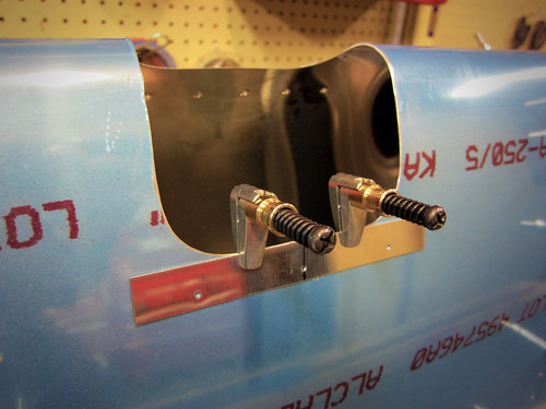
I've been on travel for the last week, but before that I did some work while waiting for a rivet helper. Specifically, I set the fully-assembled right leading edge aside and put together the left leading edge. The left side is more complicated than the right because it includes the stall warning switch, access hatch, and wiring connector. I started by attaching the previously-constructed stall warning assembly and the wiring connector to the inboard rib:
I assembled the leading edge to see how the stall warning vane adjustment was. It was actually really easy to rotate into a position where it performed as described in the plans. The switch engages after about 1mm of travel and the vane sits perpendicular to the skin tangent when at rest. Perfect. No bending of the vane or the switch arm was required.
I went ahead and riveted in the access hatch doubler so that I could get a sense of how difficult it would be to install the stall warning switch after the wing was assembled.
It turns out that it will be really difficult to install or adjust the stall warning switch through the access hatch; my forearm fills most of the open space, so I won't be able to see anything while I'm working on it. Furthermore, the location of the screws makes using a screwdriver problematic due to the proximiy of the skin. Anyway, I decided to just torque-seal the bolts and screws and leave it installed. Hopefully it won't get bumped or bent or something between now and when the plane flies because I am really not looking forward to adjusting anything here. Inspection will be straightforward; I'll just stick my little camera in there and take a picture showing the orange torque seal intact and call it done.
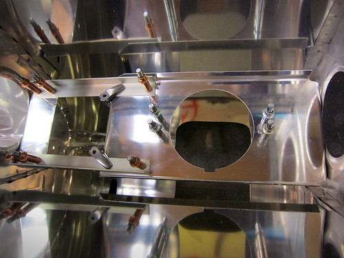
Here's a shot of the access hatch with the cover in place. It fits flush, but only with a bit of adjustment. I had to put in a bunch of the screws, then get the hatch cover aligned properly, then tighten the screws. Good enough in my book...
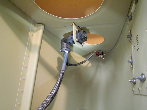
Finally, here is a view looking forward inside the inboard bay of the left leading edge assembly.
It still needs wires, and since this picture was taken some wiring work has been done. I cut the 100" lengths of 18AWG wire for the stall switch, which I determined may be a bit limiting depending on where I want to put the wing root CPC... Of course this determination was made after I made the 100" cuts and crimped on the supplied quick connects, because I'm an idiot sometimes.
I replaced the empty plug you see above with a connector cap, since the plug (and whatever accessory it is attached to) is deferred to post-flight at this point. I bought a bunch of wing wire from Stein which will allow me to wire up the connector seen here to the wing root, but I neglected to order the required CPC pins/sockets from Mouser with my most recent order, so I can't actually populate the connector yet. Eventually, the plan is to wire it up with a shielded twisted pair to possibly convey an analog video signal from a camera, then six 22awg wires for general purpose signals. This should cover any accessory I eventually mount here (except perhaps an antenna that would require some coax... but I've got plenty of room for those elsewhere in the wing).
22 Feb 2011
Got Bob to come by tonight and we ripped through all the rivets in the left leading edge assembly.
Somewhere along the second to last row of rivets was the 6000th rivet in the airplane! This assembly is now complete per the plans, but I still have to do the landing light lens and lens holders.
31 Mar 2011
It has been awhile since I updated; work has been progressing slowly. In the past month all I really got done was the left landing light lens. I started by preparing the lens bracket bars. Here are the upper two for the left side:
These two parts were riveted together onto the inside surface of the leading edge skin above the landing light hole, making a nice slot between the stop rivets for the lens to slide into:
With that done, all of the fixed parts for the landing light assembly were complete. This isn't saying much, since it's just the hole and the two parts of the upper lens bracket... Regardless, here is a view of the "finished" landing light modifications for the left side:
Moving on to the removable parts, here is the lower lens bracket riveted together with its three nutplates:
With the lower bracket taped onto the lens itself and the lens cut down to size on my tiny bandsaw, I was able to use a duct tape handle to test fit the lens. I've coated the lens in blue tape to keep it scratch-free.
I made a few trimming cuts on the acrylic to get the screw holes in the skin to line up with the nutplates on the lower retainer bracket, and then everything was looking good. Here's the lens installed, but still covered in blue tape:
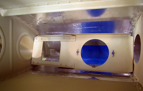
The last few steps for installing the lens require the tape to come off the lens, so I'll save them until the plane is about ready to fly. I also want to coat the inside of the bay with some thermal reflector material so that the heat of the lamps doesn't impact my paint just above the lamp; that'll need to be done before the leading edge gets riveted onto the spar. In the meantime, I installed the lamp bracket just for storage. Here's a view looking forward in the outboard bay of the leading edge showing the bracket installed:
That's really all I accomplished this month! Hopefully April will be more productive.
31 May 2011
The last few months have been really light on RV-10 work; I took a voluntary hiatus from work in the interest of slowing down progress on the wings. That way, when I get to the end of the wing kit, I won't have to wait as long until I'm financially ready to order the fuselage.
I did have a second leading edge just sitting there in my shop, staring at me, waiting to be riveted together... so over the Memorial Day weekend I put a couple hours in and got it about half-way riveted together.
Jeremy helped with the bucking bar and we were able to get through these rivets in relatively short order. It was pretty hot in the shop, so we only worked for short bursts then took a break to watch Top Gear.
I'm hoping to have this section finished in time for the June 8th progress image.
5 Jun 2011
Over the last few days it has been really hot in the shop, so Jeremy and I have been splitting up the task of finishing the rivets on the right leading edge into 15-30 minutes at a time. Last night we finally put in the last of the rivets and fixed the few bad ones that needed drilling out. With that, the leading edges are done per the plans. I started preparation for the right side landing light lens assembly as well, but didn't get too far. I riveted together the bottom side lens bracket bars and took the blue vinyl around the top side rivet holes on the skin. Finally, I coated the lens in blue tape to protect it during the fabrication process. Not feeling like cutting acrylic with the bandsaw today, I put the lens (and leading edge assembly) aside for now.
23 Mar 2012
In the meantime, whilst waiting for shop assistance to be available, I've been finding a few odds and ends to work on.
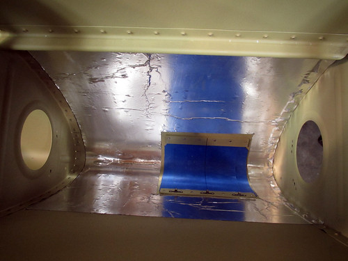
I added a bit of heat reflector to the inside of the skin around the landing light in the left leading edge. I started by ordering a 3' length of Van's self-adhesive heat reflector, which turns out just to be really wide aluminum tape. It comes in a 30" width, which is perfect because you want two 15" x 22" pieces for the two landing light bays. Without removing the backing, I laid the reflector piece in the bay and marked it where I needed to make a cutout for the landing light lens and attachment hardware. When this was removed, it looked like this:
Peeling all of the backing off at once and trying to maneuver the very sticky aluminum into position seemed like a bad idea, so I just peeled off a bit and got it stuck up under the J-stiffener, then incrementally peeled off a bit mor backing and rolling the tap into place. When it was all done, I used a wooden shim as a squeegee to flatten it out (mostly). Here's the result:
And when the landing light bracket and lens are put back in place, it looks like this:
Total time to install, about 20 minutes—most of which was futzing around trying to get the bracket screws back in place through the lens hole, which is a real pain.
Now I know that a heat reflector here probably isn't necessary; I've never heard of anyone having problems with paint discolorization or bubbling around their landing lights, but for $4 in materials and less than an hour to do both, I figured why not. I have only seen one other builder do any heat treatments for the landing light bay, and he did a high-temperature engine paint on the inside of the bay. I wanted mine to be slightly higher utility and figured that the highly-reflective aluminum will end up with slightly more light getting out the lens... so maybe that's a win? Whatever.
16 Jun 2012
The right leading edge landing light assembly wasn't complete, so I spent a bit of time this evening getting it caught up with the left side. The plexiglass lens is now cut to size and all of the metal bits are in place, though the edges of the plexi will eventually need to be trimmed up so there are no nicks or sharp corners.
I went ahead and installed the light bracket as well, if for no other reason than it is a convenient place to store the bracket.
This puts the right leading edge at the point of being ready for final assembly onto the wing.
6 Nov 2013
Prior to attaching the left wing leading edge sub-assembly to the main body, I wanted to finalize the wiring harness serving the stall warning switch and auxiliary wiring connector found in the inboard bay of the leading edge sub-assembly. I chose to wire the 9-pin auxiliary connector with three shielded pairs of 22awg wire so that if I needed to run video from this area to the fuselage I could do so.
I haven't decided yet if I will try to run this harness through the holes in the fuel tank's z-attach brackets to the forward part of the wing root or pass the harness through the spar and have it enter the main wiring conduit to the aft wing root. Regardless, the left leading edge sub-assembly is complete as per the plans and is ready for assembly onto the main wing body.
Time invested on this sub-assembly: 57 hours (46 by me)
Updates regarding the outboard leading edges
12 Dec 2010I've been doing a bit of work getting started on the leading edges. Most of it is not terribly photogenic. But just so I'll have something, here's a shot of the two plates that make up the stall warning mechanism bracket:
I had done most of the fab work on these two pieces awhile back, but the smaller holes call for a #31 drill, which I didn't have and wasn't available at the local hardware or home stores. So I finally, this weekend, went down to Harbor Freight and picked up an indexed drill set with #1-#60, A-Z, and all the fractionals up to 1/2" for $14. Nice. Now when these weird-sized holes that only exist once in the whole plane show up, I'll have a (low-quality) drill bit ready.
Anyway, now these two pieces are ready for priming. When the time comes, I'll be able to complete the leading-edge portions of Chapter 19 of the plans (stall warning) while the internal space where they go is still easy to access, rather than having to reach through the access hole on the bottom of the wing to adjust this mechanism.
In addition to these two tiny parts, I did manage to get all of the leading edge ribs fluted and the J-stiffeners cut to length. The four ribs that get their aft flanges modified have also been snipped. No pics of this.
The next step was to build the cradle, and I was procrastinating on this for a few reasons. For starters, I didn't have a jigsaw with which to cut out the templates on the lid of the shipping crate. This problem has been rectified. Next, when I opened the shipping crate, the lid cracked about 6" in one spot that just happened to pass right through the thinnest part of one of the leading edge cradle templates. Great. Tonight, I cut out the templates and predictably the one with the crack snapped in two almost immediately.
Luckily, the way it cracked left a large surface area onto which I applied wood glue and clamped the two halves back together. If this doesn't prove strong enough (I think it will), I'll just screw a backing board onto the bottom edge of this one.
18 Dec 2010
Yesterday it snowed so much that work called a snow day, and today the clouds were still low so my planned flying excursion was cancelled. Instead, I got a bunch of work done on the leading edges. First, I found a couple of old 2x4's in the garage and used them to build the side rails for the leading edge cradle. Then I took a die grinder to the fuel tank skins to separate the skin splice strip. Next, I put a small Scotchbrite wheel on the die grinder and dressed all of the edges on all parts (except the right-side leading edge skin, which hasn't been taken out of the garage yet).
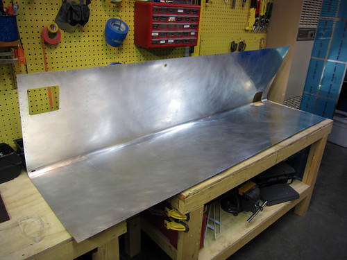
With all of that preparatory work out of the way, it was finally time to do the initial assembly on the left-side leading edge.
The only issue with the new cradle was that the two old 2x4s were really warped, so to get it to lay flat I had to clamp it to the table. Getting the holes to line up between the skin and the ribs was a challenge. And even with all of the holes cleco'd, I couldn't get the forward most holes to line up on any of the ribs. Not sure what to do about that yet.
I proceeded with the J-stiffener, which was exactly the right length. The centerline I had previously drawn on it stayed perfectly aligned in the skin holes without any work from me, so this should be considerably easy to work with than the tail cone J-stiffeners (which I had to manhandle to get to line up right). My dad, who is visiting for the week, helped me dril out the holes between stiffener and skin.
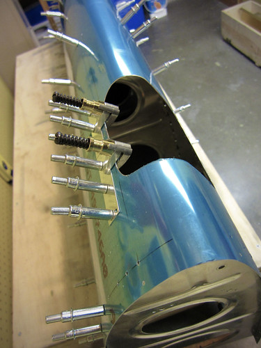
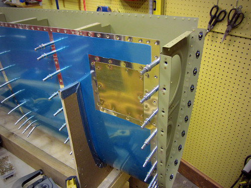
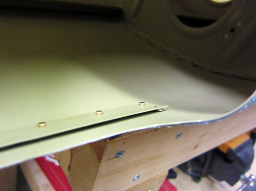
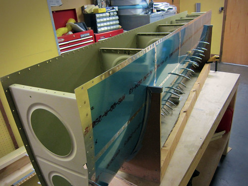
The last piece to go on was the skin splice strip, and this was the most difficult piece of the whole assembly. It is wedged between the inboard rib and the skin, which means that the holes in three pieces have to line up before the cleco has any chance of going through. Again, there were a few holes at the forward end that I couldn't get to line up at all. They're close enough that I think I can just match drill them and they'll be essentially round.
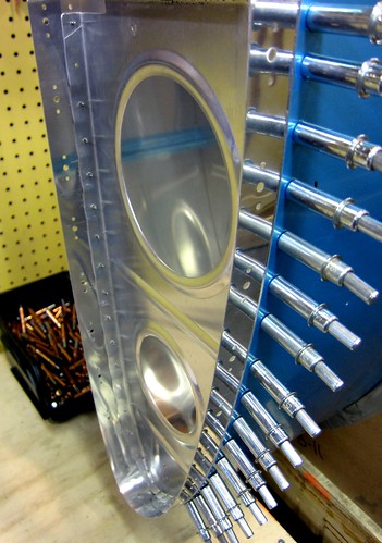
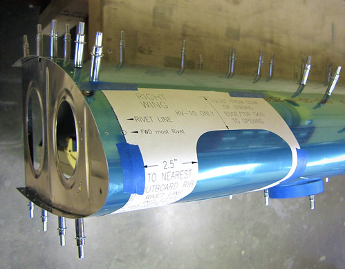
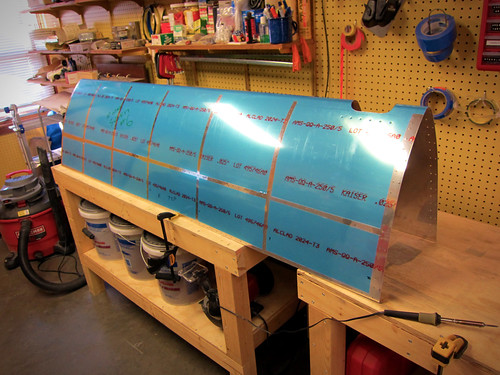
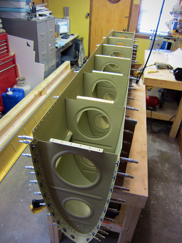
This is all ten parts that make up the leading edge assembly per the plans; the next step is to match drill all of the skin holes. I'm awaiting delivery of the landing light kits from Duckworks so that they can be installed before finalizing the leading edge assembly. I'll also be doing some of the stall warning modifications prior to priming these parts. And, of course, there's always the right-side leading edge to contend with as well.
25 Dec 2010
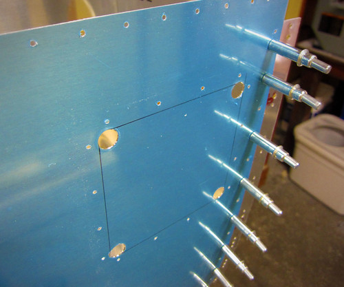
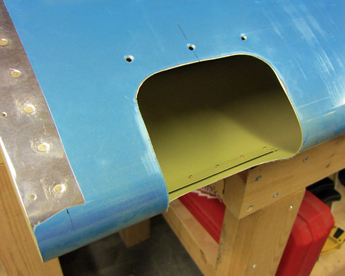
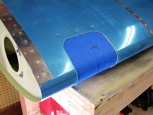
I spent some time over the last couple days doing little bits and pieces for the leading edges. On the left side, I got the stall warning access hatch doubler match drilled.
With that done, I remved it and cut off the two alignment tabs. Then I drilled the four corner holes for the hatch cutout in the skin.
I don't have a fine-tooth blade for my jigsaw meant for cutting thin metal like this, so I'll have to wait on finishing the hatch hole. Instead, I finished off the hatch cover itself and the doubler by deburring all holes and dimpling.
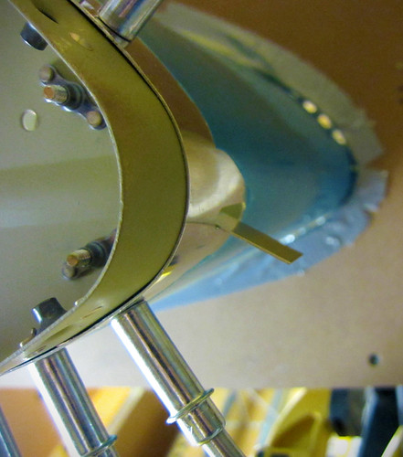
These two parts are now ready for alodining and priming. The next small task I took care of was the stall warning vane slot. This starts as just two small 3/32 holes in the skin which I enlared to #10, then filed out the material between the holes.
I'm really happy with how clean this hole came out, especially for being hand-carved with a small jeweler's file.
I set aside the left leading edge and put the right side leading edge together remarkably quick. Both assemblies are now complete per the plans up through the step where they are to be fully disassembled so that the deburring and dimpling phase can begin.
However, there are a couple of customizations I want to build in before I disassemble anything. The first is a CPC connector in the inboard bay on the left side. This will service the stall warning switch as well as any accessory I might eventually wire into this bay. The most likely candidate here would be a down-firing camera attached to the access hatch cover. I'm not planning on building that in initially, but I like to keep my options open. Running a few extra wires and adding a CPC will make adding such a thing really easy in the future.
The other customization for the leading edges is the inclusion of Duckworks Aviation leading edge PAR-36 landing light mounts. I haven't decided if I'm going to go with HID lamps or shell out for the (very expensive) LED lamps, so for now I'm just going to install the mount brackets. I've already ordered them but they are taking their time getting to me. I want to install those while everything is still fully assembled, so I'm putting the leading edges on hold until the Duckworks parts arrive.
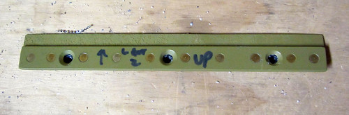
One last get-ahead task I did before moving the leading edges to the garage was to take out the splice strips and do the dimpling and countersinking for the nutplates. Reinstalled the splice strips for storage. The results can be seen in the image above if you zoom in.
28 Dec 2010
The Duckworks Aviation leading edge landing light kits showed up last night, so this morning I started a bit of work on them.
The first step was to make the template for the rib holes. This was a simple matter of glueing the included piece of paper onto some cardboard, cutting out along the line, poking the two holes through the cardboard, then marking the ribs through the holes.
Once the center holes are marked, they are drilled out to accept #10 bolts and then the nutplate attachment holes are added using a nutplate as a template.
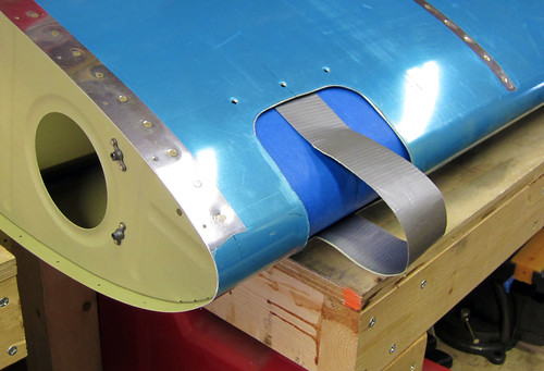
I got both of the ribs for the right wing modified in this way, then re-assembled them into the leading edge for the next step. This was to cut out the lens hole template and tape it onto the skin.
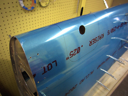
Again, the kit makes it very easy; no special measurements were required and it took very little time to get everything aligned properly. With the template in place, I just traced around the open hole with a thin sharpee and then removed the template. The next step is to cut out the traced line, either with a jigsaw or snips. I decided that snips end up bending the metal too much so I'm going to try a jigsaw, but for that I need a finer blade than I have so this step will have to wait. I did, however, drill a big 3/4" pilot hole in the center using a unibit.
It was a bit nerve racking putting a big hole in the skin of the airplane that isn't in the plans, but this isn't the first time I've done this sort of thing and this product has a strong pedigree in the RV-10 community so I'm not too worried about it.
Now I'm off to Harbor Freight to find a good thin metal jigsaw blade.
29 Dec 2010
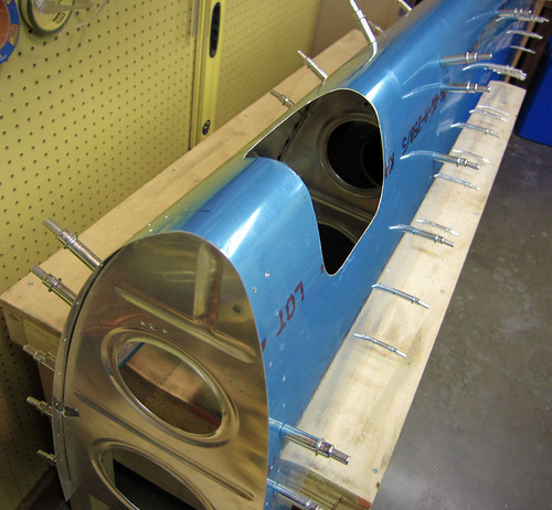
Got a bunch of work done on the right-side landing light assembly today. Started the day down in Albuqureque, so after dropping Nina off at the airport, I swung by Harbor Freight and picked up a pneumatic body saw and some fine 32tpi metal cutting blades. This was the tool I was missing to be able to make the landing light lens cutouts in the leading edges.
It took awhile to get it cut and dressed nicely, but in the end it looks really good. With the hole made, I started in on the light bracket itself. This involves separating the two sides of the bracket from each other, then fabricating a couple of angle bars to connect them. Here's a shot of the four pieces cleco'd together:
...and here's a shot of it test-fitted into the leading edge (as seen from aft):
Everything looked good in the test fit, so I deburred all the holes and got the nutplate attachment holes dimpled. Now all parts of that bracket are ready for surface treatment and priming.
Moving on to the lens retaining brackets. I got the top side pieces ready for priming without much difficulty. The countersinking of the really thin piece was a bit ugly, and to be honest I'm not sure why they don't just use a AD470 rivet there instead of the flush one, since the machine head of the rivet sticks out into free space inside the leading edge anyway... Regardless, those two pieces are also on the ready-for-priming pile. Here's a shot of the thin piece just after I finished match-drilling it to the skin:
I started to do the bottom retainer, but the instructions had some serious problems here and I couldn't continue without clarification. For starters, they state that the corner holes and rivets aren't used, so don't put the rivets in. The pictures all show the rivets; the piece they sent me doesn't even have the holes. I'm going to assume the verbage is correct on this one and that the photos are out of date (as it states). However, then it says to line the bottom strip up with the bottom edge of the hole, unlike in the picture (ok, fine). And it follows that up with a statement to do it just like it was done for the top retainer (which is what the picture shows). So it is internally inconsistent. I think what they want is for the strip and hole edge to line up, like this:
But I want to make sure before I drill any more holes in the skin. So this bit is on hold until I hear back from Duckworks. It's not much of a hold-up, since all that is left is this piece and the other strip for the bottom retaininer, then everything for the landing light is ready for priming. And the lens fitting won't get done until the entire leading edge is assembled, anyway.
5 Jan 2011
I've done a lot of work over the last few days, though most of it was deburring which is super boring and not terribly photogenic.
For starters, I got a prompt reply from the Duckworks folks who informed me that the position of the piece in the last photo of the previous post was accurate, so I went ahead and finished off the two lower lens retainer brackets. I also used the body saw to cut open the stall warning access hatch cover.
The doubler fits perfectly in the opening; I had to modify a couple of the corners to make the access hatch cover fit without modifications. I'd like to be able to use a stock cover in case I ever need to replace it (or need a second one to build a camera or sensor into).
Knowing that dimpling was coming up, I went ahead and removed the vinyl lines from the rivet lines on both leading edge skins.
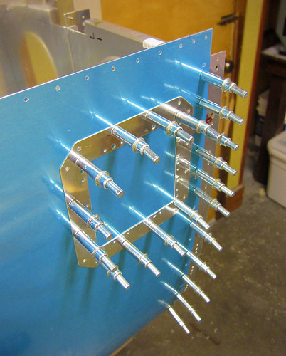
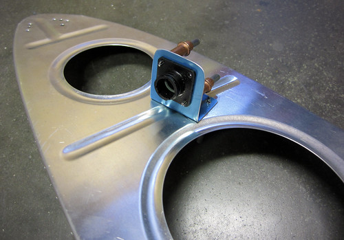
Next, I ordered and received some new Tyco/Amp circular plastic connectors. I'm going to mount one in the stall warning bay of the left leading edge. I whipped out a little bracket to hold it:
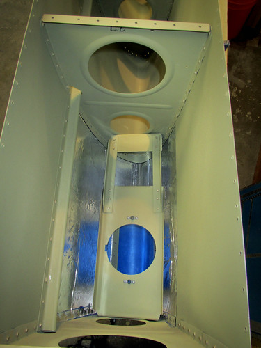
The idea here is that I can wire a full wire harness to this connector from the wing root connector in the wing. If I ever want to wire some extra sensor, camera, etc. out in the wing I can put it in this bay and only have to wire from the sensor to this connector without having to figure out how to get additional wires through the wing itself. Here's a view of where the connector is relative to the access hatch:
That concludes all of the customizations to the leading edges that needed to be fabricated before the disassembly, deburring, and dimpling could begin. I got all of the ribs in the right leading edge deburred and dimpled while I was waiting for the CPC to show up. I also got both of the skins deburred (which seemed to take forever, though in reality it was only two hours). I scuffed them up with Scotchbrite and cleaned them with acetone in preparation for priming, because this step is much easier to accomplish prior to dimpling.
This meant that the skins were ready for dimpling. But they are too unwieldy for me to do by myself. So I lured Bob and Jason from work to my house with the promise of tacos and video games in return for an hour's help dimpling skins. It was a massive success; we were able to knock both skins out quite quickly and move on to more important things like a classic Donkey Kong Tournament (winner: Jason). Sadly, no pictures of the dimpling or the results.
All that is left on the leading edges prior to priming is to debur and dimple the left-side ribs. If I can get the aileron skins dimpled and deburred and figure out how to mount the static wicks on the ailerons, I may do some priming this weekend.
17 Jan 2011
Got a bunch of little things done over the last couple weeks, but sadly there aren't a lot of pictures to show for it. For starters, I finished all of the deburring and dimpling tasks on the leading edges. Nothing really to see there; but as of yesterday they were all ready for chemistry. I also figured out where on the wingtips and ailerons I was going to mount the static wicks. The ailerons will only support a single wick each, using the second stiffener from the outboard end as a doubler. I went ahead and added nutplate holes for two anchor points to this stiffener and the skin on each side. The remaining two wicks on each wing will be in the wingtip, one right at the inboard edge, and the other a foot or so inside the tip. I'll get some pictures of the mount as I assemble the ailerons.
With the small tasks out of the way, it was time to do the first round of surface chemistry and priming. I got started on that today with a long haul day of Alumiprep and Alodine. I started with just the small parts that could be dunked in the chemical storage buckets.
There were so many small parts (32 aileron stiffeners, 8 wing spar extension doublers, all of the landing light bracket parts, and assorted other doo-dads), that this process took me basically the entire day.
All that is left for alodine treatment are the 14 leading edge ribs, the two splice strips, and the two J-stiffeners. These are all too large to be done in the buckets, so I'll have to break out the tupperware bins (and possibly the long dunk tank for the stiffeners). This will have to wait for another day. And then I can prime.
22 Jan 2011
Priming!
I reconfigured the shop for priming and laid out all of the parts on the central table.
After hanging up the plastic walls, setting up the door ventillation, and waiting the 30 minutes for the freshly mixed primer to do whatever it does during the required wait, the priming itself went very quickly. I was able to do all of the non-skin pieces except the skins and the splice strips in one pass, then all of the skins except one in a second pass, then the final skin and the splice strips in a third pass.
I left the parts out to dry overnight (and to de-stink the shop, which was almost intolerable with all of the aerosolized solvent all over the place). Very excited to be ready to rivet again!
23 Jan 2011
The only leading-edge related thing I did today was to put together the stall warning vane assembly, just because it was easy and quick.
It probably won't get attached to the leading edge until the riveting of the ribs to the skin is complete, so for now it goes on the shelf.
26 Jan 2011
Preparing the right leading edge for final riveting.
Not wanting to dive into another eight hours of countersinking for the second main spar, I decided to take a break from that and do a leading edge instead. First I did the preparatory steps of adding nutplates to several pieces. First up were the splice strips:
Here's the access hatch doubler for the stall warning system. I found it odd that the nutplates hung out over the lip of it... whatever.
I also added the nutplates in the outboard two ribs which will support the Duckworks landing light brackets:
While I was at it, I went ahead and riveted together the landing light brackets themselves:
With that, all the preparatory work was done so I went ahead and set up the cradle. Assembling the 10 pieces that make up the leading edge assembly goes really fast when the skins are dimpled, there is a lot less hunting for alignment of the ribs.
I was able to do the aft-most two holes on each side of each rib with the squeezer, so I started with that. I also went ahead and squeezed the entire inboard rib (with the splice strip). After that, it was time to use the gun so I'm going to wait for a helper. Bob was going to come over this evening but something came up, so I'm on hold now.
Of mild-to-no interest... the fourth rib in this leading edge is the 1,000th non-rivet part in the plane.
7 Feb 2011
I've been on travel for the last week, but before that I did some work while waiting for a rivet helper. Specifically, I set the fully-assembled right leading edge aside and put together the left leading edge. The left side is more complicated than the right because it includes the stall warning switch, access hatch, and wiring connector. I started by attaching the previously-constructed stall warning assembly and the wiring connector to the inboard rib:
I assembled the leading edge to see how the stall warning vane adjustment was. It was actually really easy to rotate into a position where it performed as described in the plans. The switch engages after about 1mm of travel and the vane sits perpendicular to the skin tangent when at rest. Perfect. No bending of the vane or the switch arm was required.
I went ahead and riveted in the access hatch doubler so that I could get a sense of how difficult it would be to install the stall warning switch after the wing was assembled.
It turns out that it will be really difficult to install or adjust the stall warning switch through the access hatch; my forearm fills most of the open space, so I won't be able to see anything while I'm working on it. Furthermore, the location of the screws makes using a screwdriver problematic due to the proximiy of the skin. Anyway, I decided to just torque-seal the bolts and screws and leave it installed. Hopefully it won't get bumped or bent or something between now and when the plane flies because I am really not looking forward to adjusting anything here. Inspection will be straightforward; I'll just stick my little camera in there and take a picture showing the orange torque seal intact and call it done.
Here's a shot of the access hatch with the cover in place. It fits flush, but only with a bit of adjustment. I had to put in a bunch of the screws, then get the hatch cover aligned properly, then tighten the screws. Good enough in my book...
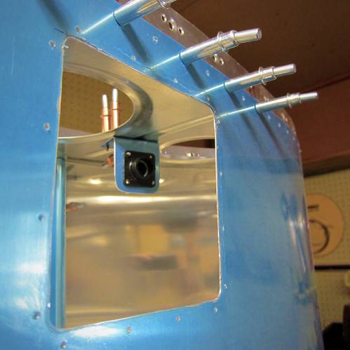
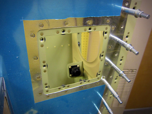
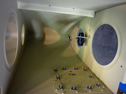
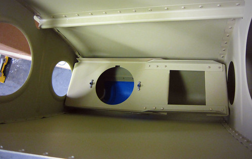
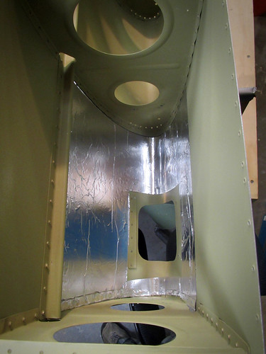
Finally, here is a view looking forward inside the inboard bay of the left leading edge assembly.
It still needs wires, and since this picture was taken some wiring work has been done. I cut the 100" lengths of 18AWG wire for the stall switch, which I determined may be a bit limiting depending on where I want to put the wing root CPC... Of course this determination was made after I made the 100" cuts and crimped on the supplied quick connects, because I'm an idiot sometimes.
I replaced the empty plug you see above with a connector cap, since the plug (and whatever accessory it is attached to) is deferred to post-flight at this point. I bought a bunch of wing wire from Stein which will allow me to wire up the connector seen here to the wing root, but I neglected to order the required CPC pins/sockets from Mouser with my most recent order, so I can't actually populate the connector yet. Eventually, the plan is to wire it up with a shielded twisted pair to possibly convey an analog video signal from a camera, then six 22awg wires for general purpose signals. This should cover any accessory I eventually mount here (except perhaps an antenna that would require some coax... but I've got plenty of room for those elsewhere in the wing).
22 Feb 2011
Got Bob to come by tonight and we ripped through all the rivets in the left leading edge assembly.
Somewhere along the second to last row of rivets was the 6000th rivet in the airplane! This assembly is now complete per the plans, but I still have to do the landing light lens and lens holders.
31 Mar 2011
It has been awhile since I updated; work has been progressing slowly. In the past month all I really got done was the left landing light lens. I started by preparing the lens bracket bars. Here are the upper two for the left side:
These two parts were riveted together onto the inside surface of the leading edge skin above the landing light hole, making a nice slot between the stop rivets for the lens to slide into:
With that done, all of the fixed parts for the landing light assembly were complete. This isn't saying much, since it's just the hole and the two parts of the upper lens bracket... Regardless, here is a view of the "finished" landing light modifications for the left side:
Moving on to the removable parts, here is the lower lens bracket riveted together with its three nutplates:
With the lower bracket taped onto the lens itself and the lens cut down to size on my tiny bandsaw, I was able to use a duct tape handle to test fit the lens. I've coated the lens in blue tape to keep it scratch-free.
I made a few trimming cuts on the acrylic to get the screw holes in the skin to line up with the nutplates on the lower retainer bracket, and then everything was looking good. Here's the lens installed, but still covered in blue tape:
The last few steps for installing the lens require the tape to come off the lens, so I'll save them until the plane is about ready to fly. I also want to coat the inside of the bay with some thermal reflector material so that the heat of the lamps doesn't impact my paint just above the lamp; that'll need to be done before the leading edge gets riveted onto the spar. In the meantime, I installed the lamp bracket just for storage. Here's a view looking forward in the outboard bay of the leading edge showing the bracket installed:
That's really all I accomplished this month! Hopefully April will be more productive.
31 May 2011
The last few months have been really light on RV-10 work; I took a voluntary hiatus from work in the interest of slowing down progress on the wings. That way, when I get to the end of the wing kit, I won't have to wait as long until I'm financially ready to order the fuselage.
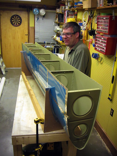
I did have a second leading edge just sitting there in my shop, staring at me, waiting to be riveted together... so over the Memorial Day weekend I put a couple hours in and got it about half-way riveted together.
Jeremy helped with the bucking bar and we were able to get through these rivets in relatively short order. It was pretty hot in the shop, so we only worked for short bursts then took a break to watch Top Gear.
I'm hoping to have this section finished in time for the June 8th progress image.
5 Jun 2011
Over the last few days it has been really hot in the shop, so Jeremy and I have been splitting up the task of finishing the rivets on the right leading edge into 15-30 minutes at a time. Last night we finally put in the last of the rivets and fixed the few bad ones that needed drilling out. With that, the leading edges are done per the plans. I started preparation for the right side landing light lens assembly as well, but didn't get too far. I riveted together the bottom side lens bracket bars and took the blue vinyl around the top side rivet holes on the skin. Finally, I coated the lens in blue tape to protect it during the fabrication process. Not feeling like cutting acrylic with the bandsaw today, I put the lens (and leading edge assembly) aside for now.
23 Mar 2012
In the meantime, whilst waiting for shop assistance to be available, I've been finding a few odds and ends to work on.
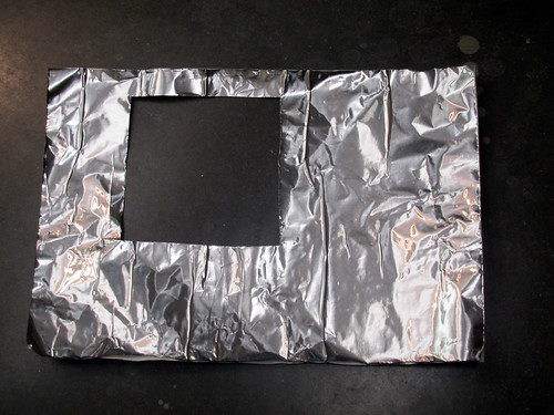
I added a bit of heat reflector to the inside of the skin around the landing light in the left leading edge. I started by ordering a 3' length of Van's self-adhesive heat reflector, which turns out just to be really wide aluminum tape. It comes in a 30" width, which is perfect because you want two 15" x 22" pieces for the two landing light bays. Without removing the backing, I laid the reflector piece in the bay and marked it where I needed to make a cutout for the landing light lens and attachment hardware. When this was removed, it looked like this:
Peeling all of the backing off at once and trying to maneuver the very sticky aluminum into position seemed like a bad idea, so I just peeled off a bit and got it stuck up under the J-stiffener, then incrementally peeled off a bit mor backing and rolling the tap into place. When it was all done, I used a wooden shim as a squeegee to flatten it out (mostly). Here's the result:
And when the landing light bracket and lens are put back in place, it looks like this:
Total time to install, about 20 minutes—most of which was futzing around trying to get the bracket screws back in place through the lens hole, which is a real pain.
Now I know that a heat reflector here probably isn't necessary; I've never heard of anyone having problems with paint discolorization or bubbling around their landing lights, but for $4 in materials and less than an hour to do both, I figured why not. I have only seen one other builder do any heat treatments for the landing light bay, and he did a high-temperature engine paint on the inside of the bay. I wanted mine to be slightly higher utility and figured that the highly-reflective aluminum will end up with slightly more light getting out the lens... so maybe that's a win? Whatever.
16 Jun 2012
The right leading edge landing light assembly wasn't complete, so I spent a bit of time this evening getting it caught up with the left side. The plexiglass lens is now cut to size and all of the metal bits are in place, though the edges of the plexi will eventually need to be trimmed up so there are no nicks or sharp corners.
I went ahead and installed the light bracket as well, if for no other reason than it is a convenient place to store the bracket.
This puts the right leading edge at the point of being ready for final assembly onto the wing.
6 Nov 2013
Prior to attaching the left wing leading edge sub-assembly to the main body, I wanted to finalize the wiring harness serving the stall warning switch and auxiliary wiring connector found in the inboard bay of the leading edge sub-assembly. I chose to wire the 9-pin auxiliary connector with three shielded pairs of 22awg wire so that if I needed to run video from this area to the fuselage I could do so.
I haven't decided yet if I will try to run this harness through the holes in the fuel tank's z-attach brackets to the forward part of the wing root or pass the harness through the spar and have it enter the main wiring conduit to the aft wing root. Regardless, the left leading edge sub-assembly is complete as per the plans and is ready for assembly onto the main wing body.