
| Workshop | Empennage | Wings | Fuselage | Contact |
Fuel Tank Construction
Current status: Under construction.
Time invested on this sub-assembly: 129 hours (111 by me)
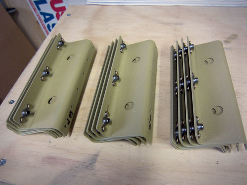
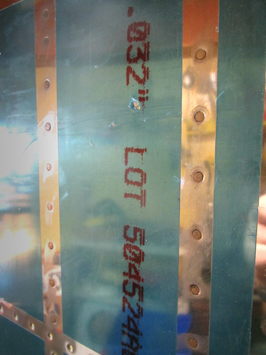
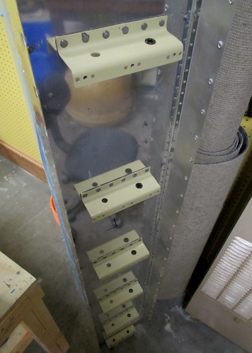
I started work on the fuel tanks awhile back in January when I did the primer pass for the leading edges. I knew that most of the fuel tanks don't get primer (until after they're assembled and sealed, if at all), but that the Z attach brackets could be primed as they were external to the tank proper. So I did a very small amount of work to get them match-drilled to the rear tank baffles and then threw them in with the parts to be primed. I did forget to countersink the nutplate attach rivet holes, though, so now those countersinks are bright silver on otherwise green pieces.
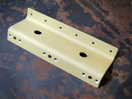
With the countersinks cut, I went ahead and riveted on the nutplates, rendering the brackets complete. These are the last thing that gets attached to the fuel tanks per the plans, but are the first parts completed. Go figure.
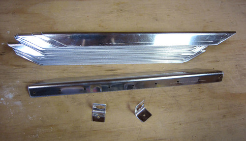
The next step was to cut out all of the tank skin stiffeners and the vent line clips. I made relatively quick work of these with my snips.
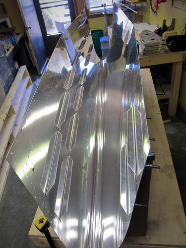
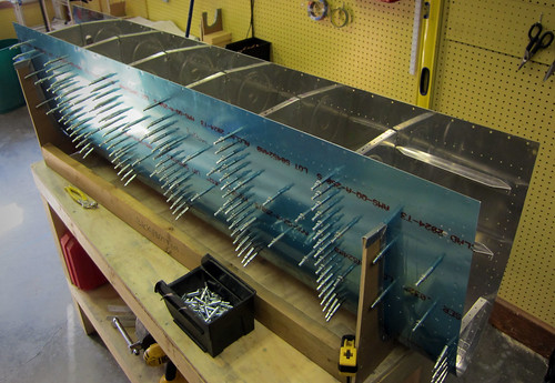
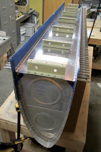
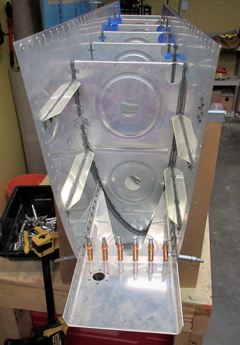
Once all of those were done, it was time for the initial assembly of the fuel tank. I started with the left-side tank. First the stiffeners went into the skin:
Then the ribs go in. For some reason this was really difficult. I had a really hard time getting the holes to line up and it took forever. But they did eventually all go in.
Having to stuggle to get a lot of those clecos in led to my hands hurting a lot and being blistered, so Jeremy helped with the cleco pliers while I match drilled all of the holes.
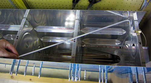
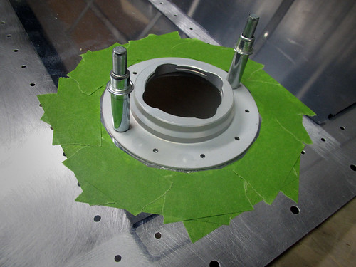
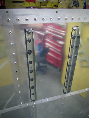
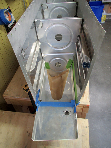
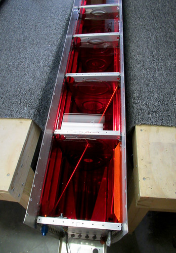
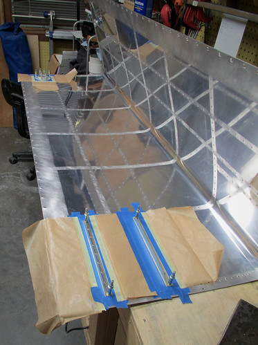
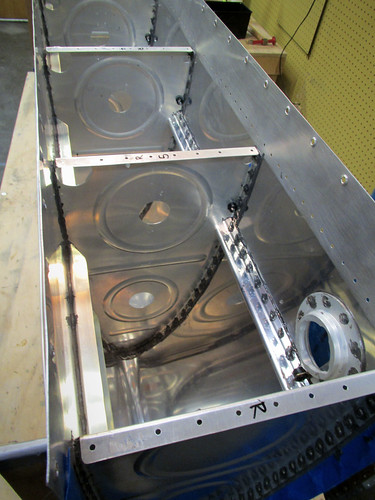
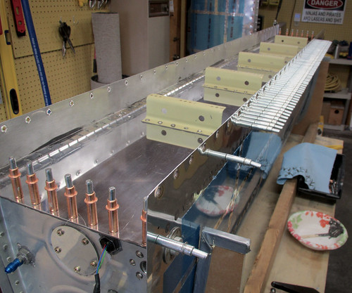
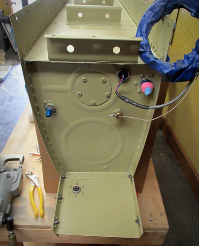
The last bit of work I did on the tanks today was to figure out where I was going to mount the fuel level sensor. I don't like the inelegant float-style sensors that Van's recommends; I want to go with a capacitance sender. The trouble with them is that the sensitive region has to be straight, so you need to find a straight line within the tank that doesn't touch anything metal and goes from as low a point as possible to as high a point as possible. The best I could do was this span from the lower-inboard edge of the inboard bay to the upper-outboard-aft corner of the second bay:
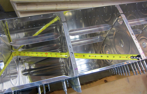
This span is about 24" long, which is conveniently the maximum length they make these probes in, and covers most of the height span of fuel in the tank. When the top of the sensor is covered in fuel, there'll be a few gallons space left in the tank, so I'll have to burn a few gallons of fuel before I start seeing a change in my fuel level readout in the cockpit, but that's not problem. Below the bottom edge is probably just a gallon or two, so empty on the gauge will be a reasonably accurate figure.
18 Jun 2011
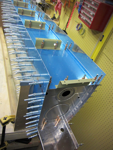
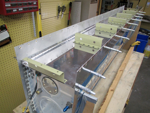
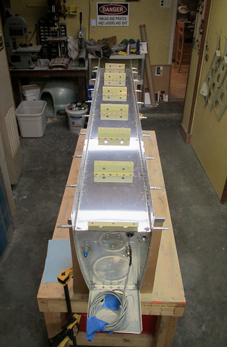
This week I got the left fuel tank up to the point of having to wait for parts I've purchased that haven't come in yet. Specifically, I got the aft baffle match-drilled as well as all of the Z-attach brackets.
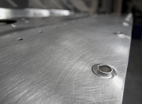
In addition to match-drilling all of these holes, I also did the countersinking of the baffle-to-skin hole lines.
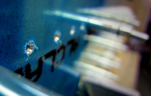
These are somewhat unique thus far in the project as they are the first skin holes that get countersunk instead of dimpled. I gather that this is done because once the rest of the tank is assembled and sealed, it would be very difficult to get the aft baffle in place past all the dimples when there is also a slathering of proseal in the way. Anyway, it's done.
The only remaining steps on the left fuel tank prior to "disassemble the whole thing" are to fit the fuel cap flange and the fuel level sensor. I've put in an order for the fuel level sensor, but it is a made-to-order part and hasn't shipped yet, so that's on hurry-up-and-wait status. As for the fuel cap, I'm somewhat underwhelmed by the ones that Van's sent with the kits, and I'm considering shelling out the extra money for the machine-contoured locking versions that are really nice. Pricey, but not absurdly so. And since I'm likely to have a sizeable financial hiatus after the wings are complete... what's another couple hundred bucks?
In the meantime while I'm waiting for these parts, I've put the left tank back into storage and started on the right tank. I didn't get very far, just got the vinyl pulled off the inside of the skin, verified that the edges were deburred (when did I do this??), and cleco'd the stiffeners and fuel drain fitting in place.
22 Jun 2011
Over the last few days I've gotten the right-side fuel tank up to the same point the left-side tank is at, which is to say bottlenecked behind the pending arrival of my locking fuel caps and capacitive fuel senders. The fuel caps are already on their way, no word on the senders yet. Anyway, the fuel tanks are both on standby for the time being.
8 Jul 2011
I put some bends in the fuel level sender probe that showed up earlier this week to test for fit. It seems to be perfect.
I am a little let down that the kit didn't include the nut and lockwasher that will be needed to secure the probe to the tank rib... but I can get that at the hardware store, I suppose.
16 Jul 2011
My locking fuel caps showed up awhile ago, but I seem to have neglected to talk about them here. They are a huge improvement over the stock fuel caps, even if you have no intention of locking your caps I suggest buying these. The mechanism and build quality are vastly superior in every way.
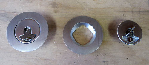
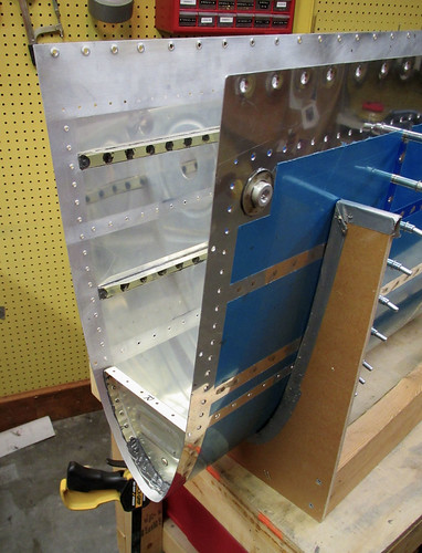
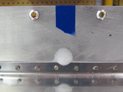
However, they do suffer from one of the same problems as the stock caps—the flanges are contoured to the wrong curvature for the RV-10 tank skin. When I hold my flange in place, the forward and aft edges are not flush at all.
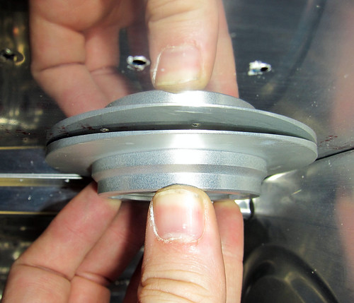
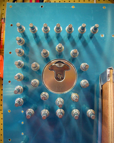
I wasn't sure if the lack of flushness was entirely due to the part being the wrong shape, or if some of it was because the tank skin wasn't fully curved without the aft baffle in place. I went ahead and drilled the holes into the right-side fuel cap flange and cleco'd it into place along with all of the adjacent hardware (including the aft baffle) to see how bad the contour fit was.
It was pretty terrible. The thin edges (forward and aft) were still standing off from the skin by many millimeters. What I needed to do was to sand down the outer contoured face of the flange to get some of the thickness off so that it would better match the skin. Unfortunately, I don't have the appropriate tool for that. In fact, I had marked several parts that needed tools I lacked for fabrication, including the fuel cap flanges, the fuel level sender access port covers, and several pieces of tube stock for aileron actuation. Last week I had a chance to run over to Pat Turner's shop with Bob and we did some quick fabrication work on these parts.
First, we cut the main aileron pushrods to length as well as the small steel pushrods that connect the aileron itself to the bellcrank in the wing. Next, we loaded the fuel cap flanges into a lathe and turned off about half the thickness of the highest parts.
The result was a flat section across the middle side-to-side, and a bit of contouring reamining on the forward and aft edges.
The next step will be to sand some curvature back into the central part of the flange with a belt sander, but I wanted to test fit these first to make sure it was helping. Turns out it needs a bit more taken off before the curvature is applied. But it is a lot better than it was!
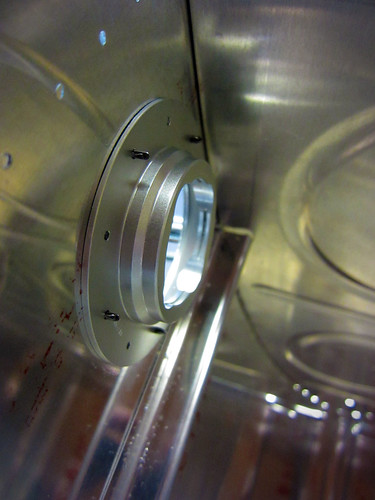
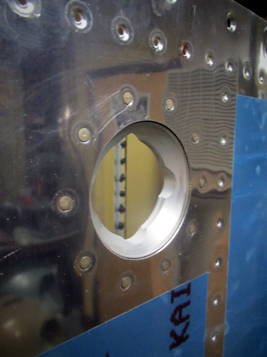
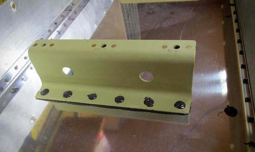
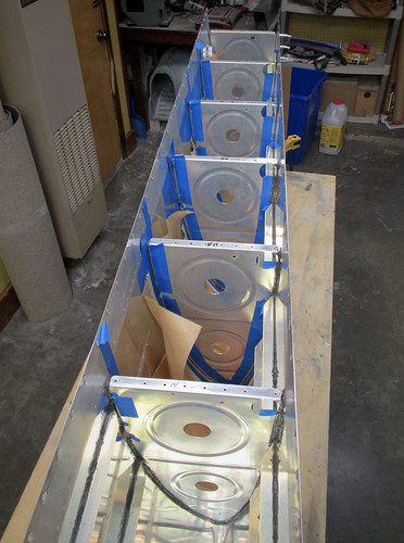
The last thing we did at Pat's shop was to cut out some covers for the fuel level sender holes in the tanks. I had ordered the T-411 parts from Van's, but unfotunately they are for all Van's aircraft models except the RV-10. They advised me to send them back and just fabricate my own; I skipped the first part and just used the T-411s as stock for my custom ones. Having access to a CNC mill at Pat's shop, we cut out perfect 2.65" diameter circles.
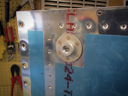
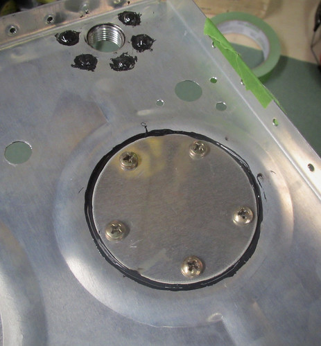
Once the circles were cut, I clamped them into place on the fuel tank inboard rib and drilled out the screw holes.
Notice that in this picture the cover plate is inside the tank; this is just for ease of match-drilling the holes. The plate will be screwed onto the exterior of the tank during final assembly.
8 Aug 2011
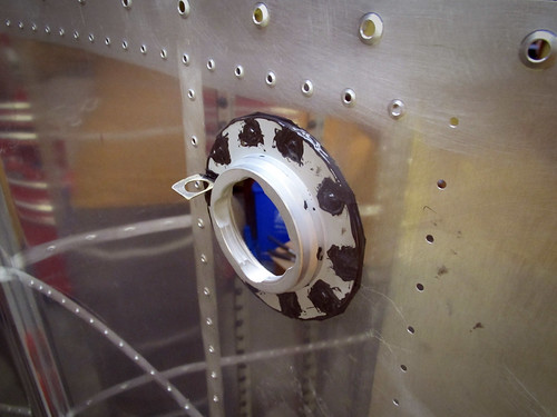
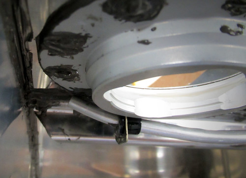
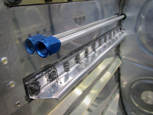
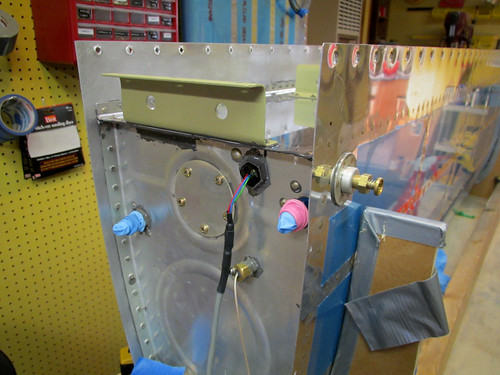
I selected a location for the Aircraft Extras Fuel Guardian sensors that I purchased last year. The nut on the sensor head fits perfectly in the anti-rotation plates used on the fuel vent fitting, so I'm going to order a couple extras to use with the Guardians. Unfortunately, making room for the anti-rotation plate limits the places I could locate the sensor. I decided to go for a relatively low position, which in turn limits the time between when the sensor will go off and when the tank will run dry.
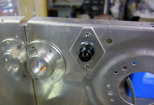
As you can see, the distance from the sensor head to the fuel intake is not much. Just a couple inches. I estimate this'll give me about a 10 minute warning on fuel. That's not a whole lot, but I'm intending for the Fuel Guardian to be a redundant backup to the EFIS' fuel level monitoring anyway, so I'm OK with that. If I'm approaching a fuel-exhaustion event, the FG light will come on and I'll have to land immediately. Or, more likely, just switch tanks (and then land).
3 September 2011
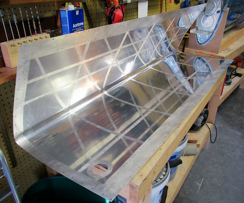
It's been a long time coming, but the fuel inlet flanges are finally conformal with the curvature of the skin.
I've been using a belt sander to grind off some of the exaggerated curvatore these locking fuel caps came with, but I didn't want to go too far, so it has been a process of many iterations. Unfortunately, I didn't have a belt sander so this involved taking them in to work for about 30 seconds of work, then back home, test fit, rinse, repeat. This weekend I broke down and bought my own belt sander, which I love already, and finished the job. It still took a long time and I almost burned my thumb on hot aluminum, but they now fit beautifully.
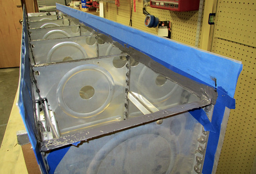
This was the only thing holding me up from disassembling the fuel tanks, which I proceeded to do immediately. I had previously drawn outlines around all of the contact surfaces on the skins so I know where to scuff prior to dimpling, and this was my first chance to see them all:
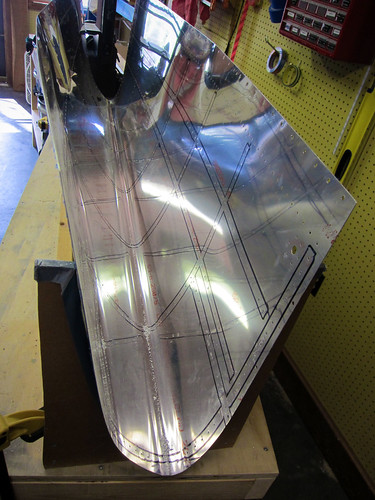
This should help keep the alclad coating intact wherever possible. The last thing I did tonight was clone the holes for the custom fuel tank accessories (fuel guardian sensor head and capacitance fuel level sender) into the inboard rib for the left tank. Having already figured out where everything should go and what size holes were needed on the right tank awhile back, this was a reasonably quick operation.
3 Mar 2012
Fuel tank finaly assembly has begun!
I grabbed the left fuel tank skin and deburred it inside and out. The edges were already deburred for some reason, so I moved right ahead with removing the vinyl lines. The last thing to do was to scuff all of the places where two pieces contact each other. For the most part this just meant masking off the lines I had drawn last time the tank was assembled and rubbing the rivet lines with Scotchbrite. The fuel fill flange and drain required a bit of fancy masking...
OK, that was probably overkill... but the resulting scuff ring looks very nice and circular. Too bad no one will ever see it once I button the tank up.
The last thing I did before dimpling was to give the inner tank surface a thorough cleaning with acetone. I wanted to make sure I got all of the metal dust from the Scotchbrite off of there, along with any finger oils, etc. that might prevent the Pro Seal from sticking as well as it might. I invited Jamie over this weekend to lend a hand supporting the tank skin while I operated the DRDT-2 dimpler with the special tank dimple dies. We worked through the entire skin in just over half an hour, then it was time for working with Pro Seal. Let the fun begin.
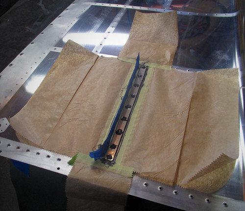
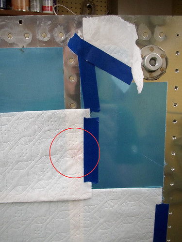
I took a cue from Mike Howe's project and used Easy Mask combination tape/paper to make a protected area around each piece so that over splatter from the inevitable thin strings of Pro Seal that go everywhere wouldn't turn my inner surface into some kind of Jackson Pollock tribute. It worked great.
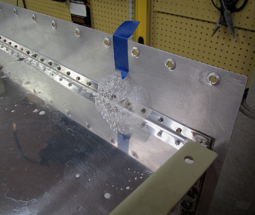
I used a $25 kitchen scale purchased from Amazon to measure out 20 grams of the white sealant compound, then an additional 2 grams of the black accelerant. I used some super high tech stuff to mix it, namely a plastic knife and a paper soup bowl. It smelled exactly like everyone had described, which is to say quite awful. Not wanting to waste the 45-60 minutes of set time, I set right to work on the tank skin stiffeners. I'm glad I spent as much time laying out everything I might need beforehand, as those 45 minutes went by really quick. I put a healthy coating of Pro Seal on the contact face of the stiffener, cleco'd it into place, then added one rivet at a time after putting a little dab of Pro Seal on the end of each one. Once all the rivets were in place, I put some rivet tape over them so that the excess sealant wouldn't get all over my back riveting plate. The back riveting process got sealant all over my rivet set, which had to be cleaned off with a paper towel after each set of three rivets lest it clog up the spring-loaded sheath on the set. Fun times.
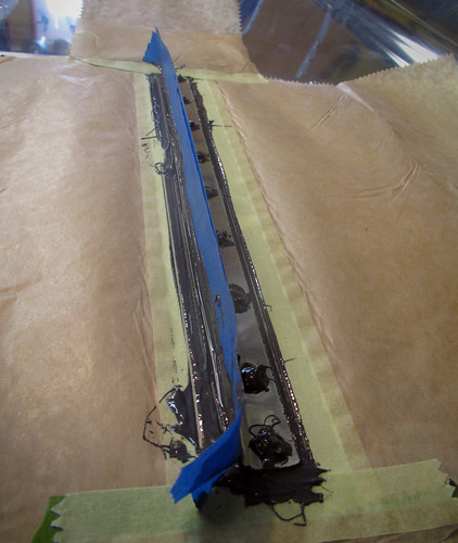
Above you can see the Easy Mask paper as well as a couple pieces of blue painter's tape that I used to keep pro seal off of the vertical part of the stiffener. Once I had done all of the back riveting, I went around the edge of the stiffener/skin joint and made a good fillet of Pro Seal with my plastic knife. Then I took a dollup of Pro Seal to each of the rivet shop heads. In this way, none of the interfaces between parts or parts and rivets were visible. Just lots and lots of sealant. Here's a closeup:
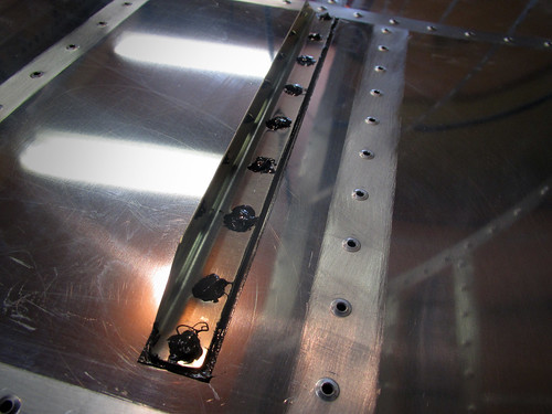
I wasn't sure how long to wait to remove the masking once I was happy with the state of the sealant, so I tried just removing the first one immediately. It worked great; no need to wait. Here's the result:
Here's what the shop head on the first set of rivets looked like before I removed the rivet tape:
That's actually a lot more excess than on later rivets. I got a system worked out where I would have just enough sealant on the outer side to be visible around the rivets but not huge rings like this. Each time I finished a stiffener, I'd stand the skin up on its side, take the rivet tape off, and wipe off all of this excess sealant with a paper towel. It wasn't too difficult since the Pro Seal hadn't set yet. The resulting rivet lines look great. Just a hint of a sealant ring around some of them.
And just for kicks, here's one more view of a couple complete stiffeners as seen from the inside:
So here's some notes for anyone else reaching this stage: 20 + 2 grams of Pro Seal was too much; I wasn't able to use it all before it hardened up. I think I probably could have done four stiffeners with that much if I had been careful, but by the time I finished my third stiffener the sealant was getting noticeably difficult to work with. I recommend going with 10 grams of sealant and 1 gram of accelerant at a time and try to get two stiffeners done with that much. Do the dollups on the top of the rivet heads last as they can be done later if you run out of a batch.
Three stiffeners using the techniques described above took me about an hour. The tank assembly is clearly going to be a long process; but I'm excited to be doing final assembly again!
6 Mar 2012
The Pro Seal Fiesta marches onwards.
I'm still working on getting all of the stiffeners riveted to the left fuel tank. I've got 12 of 14 done. I've found that mixing 10g of white sealant with 1g of black accelerant gives me plenty for two stiffeners and then a dollup left over to do some of the other accessories. Rather than bore you with pictures of each identical stiffener as I add them, here are some of the accessories that I've gotten mounted. First up, the fuel drain flange on the bottom-inboard-aft corner of the skin:
I made sure that all of the rivets had a ring of sealant around them when squeezed (I've since wiped it away on this side) and that the flange itself has a good fillet of sealant around its outer edge where it contacts the skin. On the inside, it looks like this:
Here, I put a large dollup of sealant on each rivet's shop head to make sure ther were no leaks around the rivets themselves. I also made sure that there was a good fillet of sealant between the skin and flange inside the hole, but that sealant didn't get onto the threads.
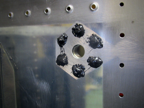
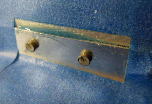
The next thing I did was to attack the tooling holes in the inboard and outboard ribs. The plans call for fabricating a small plate and riveting/sealing it in place, but I figured why not just fill the holes with appropriately-sized rivets? I had some AN470AD6-7 rivets laying around from something else and they fill the holes perfectly. I just coated the shaft of each rivet with sealant and then pounded them into place.
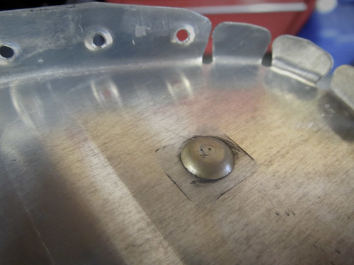
There was a big ring of sealant around the machine head of the rivet after I got it set, which I wiped away before this picture was taken. I just wanted to make sure that there was a thin layer of sealant between the machine head flange and the rib web. On the shop head side, I just covered the whole thing in a bunch of sealant (masked nicely with tape).
The -7 rivet is way too long for just going through this piece of skin, but in this case it is not structural at all and just needs to set enough to hold firmly in place. There are two of these on the outboard fuel tank rib, two on the inboard nose rib, and two on the inboard aft rib.
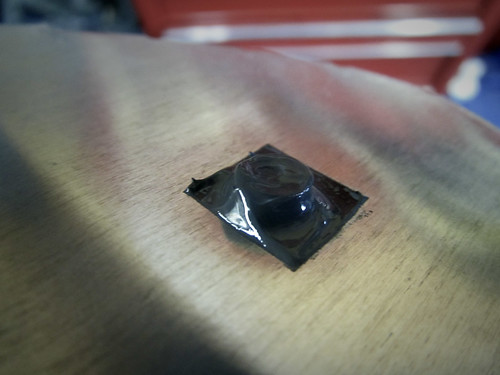
Next up was the fuel pickup flange, which was basically the same idea as the fuel drain flange. After that I did the inspection cover. I'm using capacitance fuel level probes, so I don't need the floats that usually mount through the inspection port. Instead, I just fabricated a port cover plate and semi-permanently installed it.
Technically it'll be removable, but it's got a ton of sealant holding it on. Plus, I'm going to cover the screw heads in sealant as well as all of the nutplates and exposed threads on the inside. So getting this cover off will be a real chore. Hopefully, it'll never have to happen. Here's a view of the inside as it stands now, without the sealant applied to the nutplates and screws:
That's as far as I got tonight. Somewhere on the 12th skin stiffener was the 7,000th rivet in the plane! What's left prior to rib installation in the skin is:
10 Mar 2012
Still slowly progressing through the left fuel tank final assembly. Got all of the stiffeners installed as well as the fuel cap flange and all of the bits that rivet onto the aft inboard rib. Here's the fuel cap flange:
I think the outside looks great; all of the rivets came out well and the thin fillet of sealant between the skin and the flange is perfect. Here's a shot of the inside, showing the installed vent line clip and all of the sealant fillets and rivet head coverings:
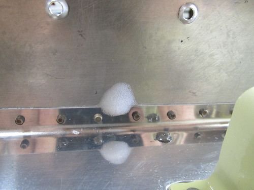
There were numerous instances on all parts where I had made a fillet of sealant connecting the part to the skin, only to have a bubble pop in the sealant overnight and leave something that looked like this:

I can't be certain tha some of these voids won't allow leaks (and there were a couple on the aft inboard rib where I could see light coming through them, so obviously leaky there...). I had to go around and mark all of them, then hit them with a dab of sealant in the next batch. At this point I'm pretty sure that all of the bubbles in the stiffeners, aft inboard rib, and fuel cap flange have been taken care of. It's going to be hard to inspect for these once I get the ribs in, so I'm going to start using more sealant around the edges to guard against this.
Speaking of ribs, everything else was done so it was time to move on to the first of the ribs—the forward inboard rib. Here's a shot of it in progress, just after getting all of the rivets squeezed and starting to lay on the sealant:
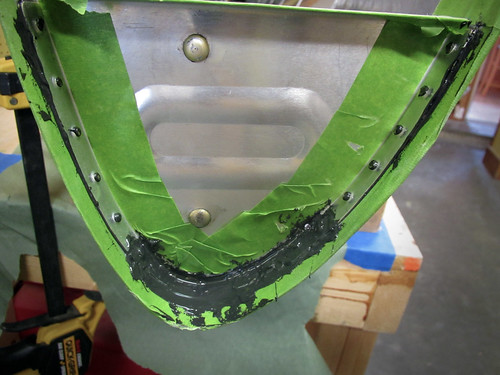
Because this is an outer surface of the fuel tank, I put an extra huge coating of sealant on the holes at the forward bend in the rib. I also used quite a bit of sealant in the fillet on the inner surface. Here's the inner fillet:
Despite using tons of sealant along this edge, on both sides, I still managed to allow one of the holes to open up and require a touch-up.
Jeremy was avaialble early this afternoon so we set about installing the first full rib. It went pretty well, with no significant problems.
Between the pre-installationg cleaning of parts, the masking of the skin and rib, the mixing and distribution of sealant, the riveting, and all of the cleanup, installing this one part took about 2.5 hours. Only an hour of that was riveting. So the overhead on fuel tank assembly is pretty severe. Here's a picture of the other side of that rib with the very nice-looking fillet around the edge:
I'm going through paper towels and nitrile gloves at an astounding rate, but so far I'm pretty happy with my progress and feel reasonably confident that I won't have any leaks from the parts I've done thus far. Five more full-sized ribs and the aft half of the inboard rib to go...
23 Mar 2012
Getting help with bucking for the interior bits of the fuel tanks turns out to be difficult, so progress has been a lot slower than I'd hoped on the left fuel tank. I'm up to three of the five interior ribs done now. I had some spare Pro Seal on the rib that got done tonight so I used it to install the tank vent fitting and nut in the inboard rib. Here's how it looks on the outside:
And here's how it looks on the inside:
The outer end of the fitting will be used to attach a manometer during the tank leak check, but otherwise will not be touched again until the wings are attached to the fuselage, which is a long way off.
The inner side of the fitting gets attached to the vent tube, so I went ahead and cut a piece of soft aluminum tubing to length, straightened it, and used my new flaring tool to give it a nice 37° flare. Here is the result:
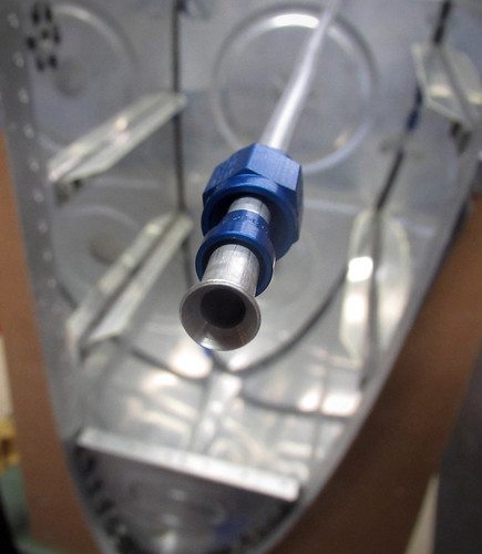
Flaring is super easy and I was very happy with the results. This tube assembly now gets set aside until I've finished all of the tank ribs and the J-stiffener.
While waiting for shop assistance to be available for bucking the ribs, I've been finding a few other odds and ends to work on.
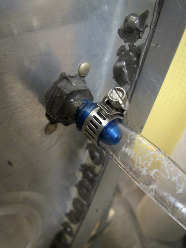
For starters, I finally figured out the right hardware to attach the Princeton capacitance fuel probes to the fueltank rib with. Why they don't ship with it is a mystery to me, but whatever. The answer is a brass 1/4" NPT compression fitting nut which McMaster Carr sells for under a dollar. For those familiar with compression fittings, note that you do not need the sleeve; just the nut. I did run into a problem with the fuel probe that I had already test-fit, because where I had bent it, it was now slightly larger in one dimension than 0.25" and the tolerance on the hole in the compression fitting nut is quite close.
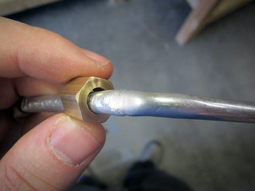
The solution was just to drill out the hole in the nut to 0.29", which is what the widest part of the bends ended up being. I'm not counting on the compression fitting for a good seal (everything will be coated with Pro Seal on the inside anyway), so the added gap around the tubing when secured shouldn't be an issue. There's still plenty of shoulder on the nut to make tight against the fuel probe.
30 Mar 2012
I had bronchitis there for a week or so, and as a result not a lot of work got done. But a few things did happen here and there.
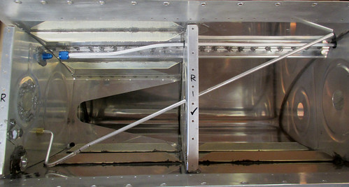
For one thing, I did manage to get all of the ribs installed in the left fuel tank:
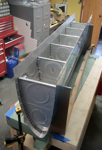
I ended up doing a couple passes of touch-ups with Pro Seal to make sure there weren't any bubbles or pinholes in the fillets around the ribs, so I'm reasonably confident at this point that there won't be any leaks from the rivets I've put in thus far.
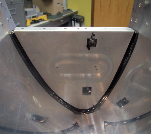
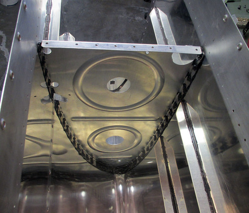
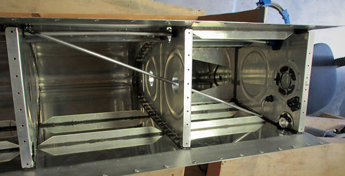
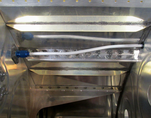
I got Jeremy to help me put the J-stiffener in as well. It was somewhat of a challenge to do the forward fillet behind the curl of the stiffener. I ended up just putting a blob of sealant on my (gloved) finger and sticking it up underneath the stiffener. Then I'd go back with a popsicle stick and try to smooth it out, blind. Finally, I'd have a look with a mirror and a flashlight to see how I did. I probably went a bit heavy with the sealant here which made it a lot easier. Here's a shot of the inboard bay with the J-stiffener installed.
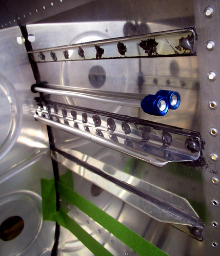
Also visible is the installed vent tube. This was trivial to do, since it just involves 6 snap bushings and the already-fabricated tube. The hand-bend in the outboard bay to line up with the vent clip was trivial, and I expect the bend in the inboard bay to line up with the bulkhead union to be similarly easy. Once I get the inboard aft rib installed, I'll hit each of the snap bushing/tube/rib intersections with a bit of Pro Seal to keep it from vibrating around too much.
The whole reason I put aside the work on the main body of the wing and started assembling this fuel tank was because it was cold out and I wanted to do the chemistry phase of the main body work outside if I could. This weekend's forecast is for great weather and warm temps, so I may shelve the fuel tank for awhile and go back to working on the rest of the wing.
9 Sep 2012
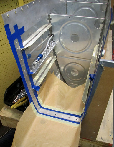
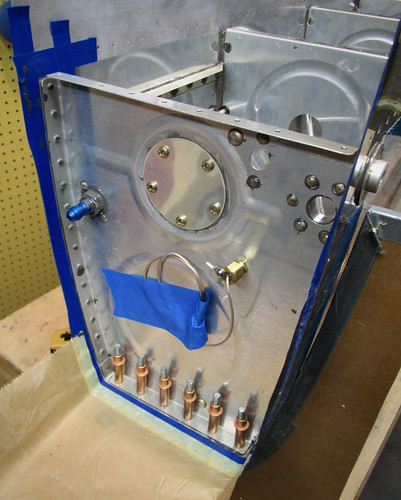
Pulled the nearly-complete left fuel tank back out of the garage now that the shop was clear of other wing parts, and worked on getting the fuel tank attach bracket riveted in. This was the first bit of fuel tank sealant work that I did solo, and it really slows things down. My advice to other builders is to have an assistant whenever you can find one for ProSeal work.
Step one was to put the part in place and mask off all of the areas I wanted to make sure didn't get ProSeal all over them. The pre-taped masking paper worked wonders in the forward end of the bay (below the bracket in the photo above). The tape also helped remind me not to apply sealant or rivets to the holes that are shared by the aft inboard tank rib which will be installed later.
Next I removed the part and cleaned it with acetone. I mixed up one 10g batch of ProSeal and applied it to the sides of the bracket as well as the aft side of the forward inboard rib flange.
The riveting was straightforward, even solo. Because it is the open end of the fuel tank, the reaches aren't terribly awkward and good control of the rivet gun was relatively straightforward. The initial 10g of ProSeal covered the mating surfaces and the caps for all 20 rivet shop heads. I mixed up a second 10g batch to cover a few small pinholes I had discovered elsewhere in the fuel tank sealant joints and to do the fillets around the edges of the tank attach bracket. The underside is a trick because the fillet has to be done blind. This meant just using a (gloved) finger with a big blob of sealant on it to smear it in there. Luckily, no one will ever see that.
With that done I did a thorough inspection of all sealed surfaces and fillets with a mirror-on-a-stick and a flashlight and discovered a number of additional cracks and pinholes that I wasn't happy with so I decided to make a third 10g batch of sealant to fill them. I used the excess to do a second go on the underside fillets of the tank attach bracket since it was difficult to do any meaningful spot touch-ups there. It's a mess under there now, and there's way more sealant there than ideal... but it probably won't have any problems with leaks and that's what I care about most.
Only two major pieces of the fuel tank body left, the aft inboard tank rib and the aft baffle. The rib is the next part but it will take some prep because it needs to have all the fuel sensors attached to it first.
16 Sep 2012
My parents were in town for the weekend so my dad helped me get the inboard aft rib installed on the left fuel tank.
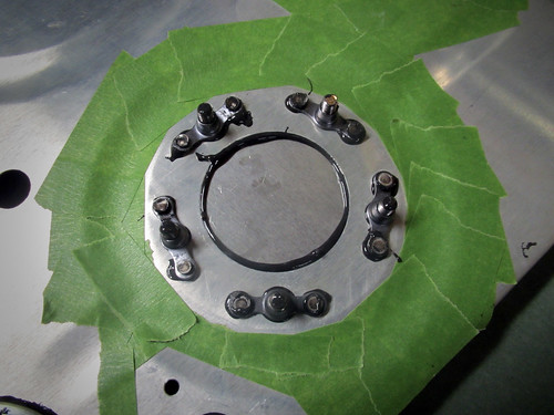
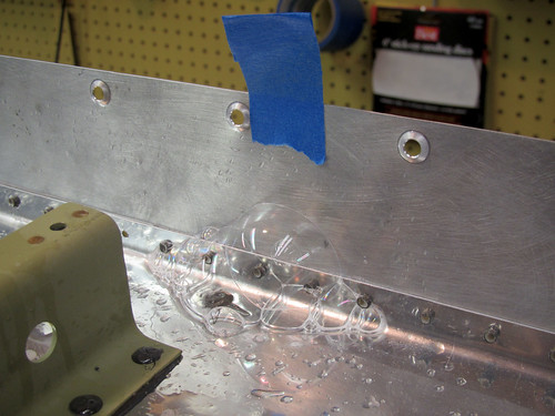
Prior to installing the rib I had to finalize the shape and position of the Princeton capacitance fuel probe. I had one that I had previously bent into position but I had had to un-bend it to get the compression fitting on. When I went to re-position the tube into its original bend positions, the tube failed and broke into two pieces. So I'm going to need to order a replacement there. My advice to anyone using these probes is to only bend them once. For RV-10 builders, you can attach the tube straight onto the rib prior to intalling it, go ahead and torque down the compression fitting, then bend it into position, and finally do the install of the rib without having to modify the bends at all. Do that, and you won't risk a repetitive stress failure of the aluminum like I did. Also, you'll save yourself $200, like I didn't.
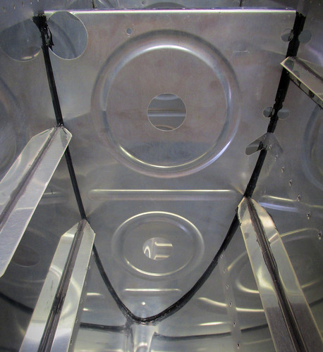
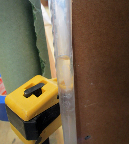
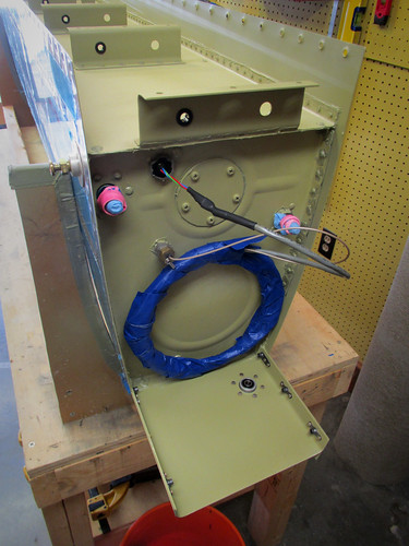
Anyway, the bends that you'll want to put into the 24" probe with a 5" bend region at the base is to go 90° down immediately after the compression fitting. Just before the tube reaches the bottom skin, bend it back up at about 135° (see photo, below). Clock the bends such that the tight 135° bend is just forward of the aft-most stiffener in the first bay of the fuel tank. Doing this allowed my probe to pass through the aft hole in the second rib without any risk of touching the sides. I also was not at risk of the probe touching the skin stiffener, so it is only sealant-separated from the fuel tank body at the far (upper) end.
I used a small piece of plastic to hold the upper end of the probe away from the skin, then coated the whole thing with sealant to hold it in place on the skin, being careful not to plug the open end of the probe.
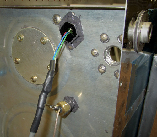
Here's the outside view of the inboard aft rib with the electrical connections in place:
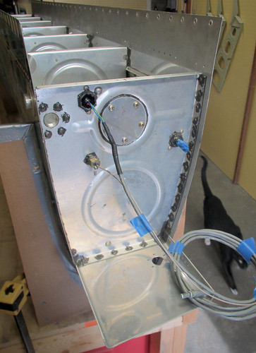
I went ahead and put the final bends in the vent tube and connect it to the bulkhead union fitting. Both sides of the union were coated in sealant since it never needs to be adjusted again. I sealed up all the bulkhead joints on the Aircraft Extras Fuel Guardian sensor and the fuel level probe, both inside and out.
The next step will be to install the aft bulkhead which essentially completes the fuel tank, assuming no leaks. However, before I close it up I'm going to have my EAA technical advisor come by and look at it.
23 Sep 2012
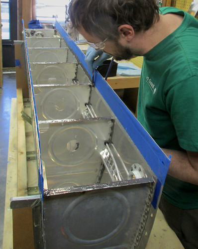
My EAA technical advisor came by last week to look inside the fuel tank before I sealed it up and he liked what he saw. He did recommend that, before I put the back on it, that I find a way to fill it up with water to test the the rivets that are already done so that if any of them need to be fixed it can be done before the aft baffle is in place. I talked this over with Bob while I was in the shop yesterday and he recommended that I just tape toilet paper to the rivet lines and use some food coloring in the water so that it will show up really easily if there is a leak. So that's exactly what I did:
It didn't take too long to get toilet paper stretched across every rivet line on the skin (I'm less worried about the rivets and accessories on the inboard and outboard ribs because I can always put more sealant on those after the fact without having to open anything up).
To support the ~240 pounds of fuel tank when it is filled with water, I took some industrial carpeting I have a spare roll of and laid it out across my two workbenches with a bunch of slack between, sort of like a larger version of the carpet wing holders on my wing cart:
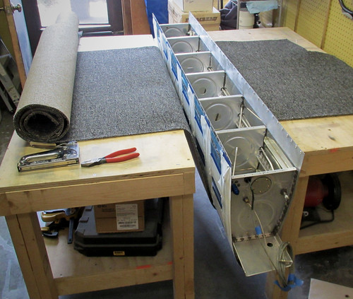
I stapled the carpet down to the table tops with nine 1/2" stapes on each side. I tested that it could handle the weight by standing in the loop and doing a little jump. No problems. I had to carefully put the tank in place so that I didn't disturb the toilet paper lines, but this ended up not being difficult. Then, it was just a matter of filling up a 5 gallon bucket over and over, putting some food coloring into it, and dumping it into the tank.
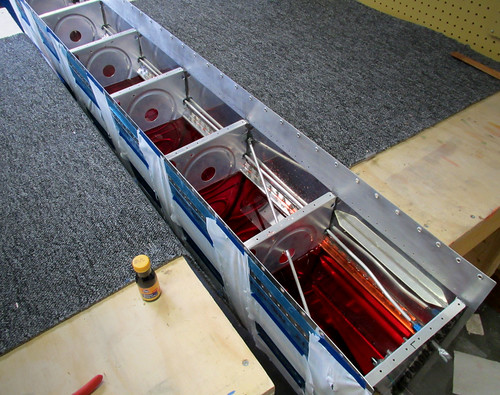
That's the tank at half-capacity. The red water looks almost like Kool-Aid. Yum!
When I got to 27 gallons in the tank, the vent line filled with water and my cheesy duct tape seal on the end was starting to drip, so I started siphoning out the tank at that point. Here's as full as I got it:
Three gallons short of capacity meant that it was missing the aft-most rivets on both sides and a couple of the rivets on the fuel cap flange, but these are the easiest rivets for me to inspect and access prior to putting the aft baffle on, so I'll just give those an extra close inspection and perhaps a touch-up with ProSeal before I close up the tank.
The siphoning process took a long time, and pouring out 27 gallons of blood-red water into my lawn earned me a weird look from my neighbor... but in the end I was able to undertake this test with no mess and, more importantly, no leaks!! Whew.
Somewhere during this test was the 700th man-hour spent on the plane. And now, it's time to install the aft baffle, I guess.
28 Sep 2012
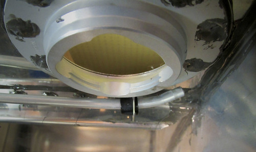
At the advice of my EAA tech advisor, I bent the fuel vent tube up behind the fuel cap flange as far as I could to add capacity to the tank.
I estimate that this 1.5cm increase in height of the tube entry probably added a gallon of usable capacity to the tank. Woot!
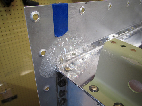
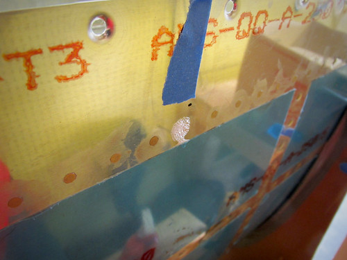
Next, I did a 5-hour marathon session to get the aft baffle onto the left fuel tank. I masked off the bits of the tank skin that extend aft of the aft baffle, then added a small strip of masking that went from the forward edge of the baffle flange rivet holes, aft to my existing masking. This way I can just slather on sealant on the skin where the baffle flanges will contact it, then remove the thin masking line and the aft half of the flange joint will be clear to avoid pillowing of the skin. The plans seem to be really concerned about this possibility and advise that it'll make the fuel tank difficult to mount onto the rest of the wing, so I wanted to make sure I didn't encounter any problems. Here's a picture of the masked fuel tank with all of the sealant in place (I used a 30 gram batch of sealant to set this up):
And here's a corner of the tank once the aft mask line had been removed, exposing the rivet holes:
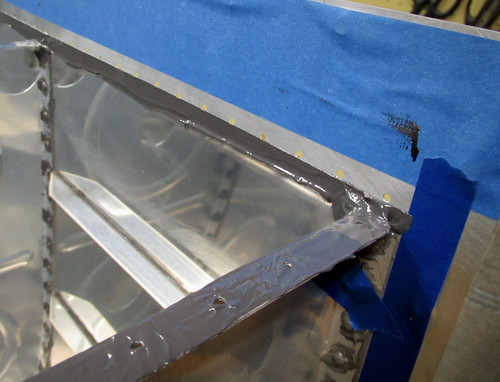
You can also see in that photo the big blob of sealant that I put in the corner to prevent the big hole in the rib corner from leaking.
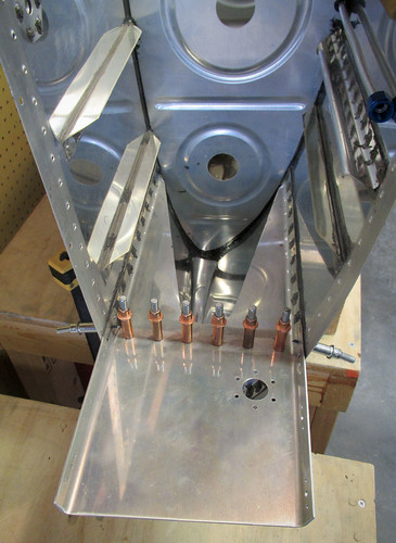
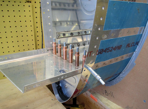
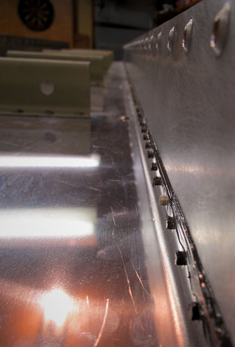
Lowering the baffle into place wasn't a problem. It took awhile to get all of the clecos into place on the skin/flange joints (the plans instruct to fill every hole). I then mixed up a fresh 10 gram batch of sealant and set about riveting in the Z-attach brackets. I did the center five first since they were all pull rivets. I followed that up with the outboard rib because they could all be squeezed. Last I did the inboard rib because they all needed to be shot, but they were easy to do solo. The 10 grams of sealant was plenty to do all of the Z-brackets and start on the skin rivets. Here's the result:
With the aft baffle and Z-brackets in place, the long process of doing all 151 skin-to-baffle rivets began. I put sealant in mine just because I want to do everything I can to prevent leaks. No idea if it was necessary, but it sure did slow everything down. Two batches of 10g sealant mixtures was plenty for all of these rivets plus reinforcing the aft corners on the inboard and outboard ribs where the plans suggest the design to be leak-prone. Here's a view of the tank with all of the rivets done except for every 10th rivet which was was not countersunk so that the clecos could act as guide pins when fitting the aft baffle:
Those clecos will be removed once the sealant has cured, then the holes countersunk and the last rivets added. I may do this after I leak-check the tank in case I need to add sealant anywhere else; 10g of sealant is going to be way overkill for just these 20 rivets.
Also in the possibly-overkill department is my treatment of the blind rivets on the aft baffle:
I don't know how reliable a sealed-end blind rivet is, and the little holes in the tops when the pull rod is removed made me nervous. So I covered the top of each one with a little blob of sealant just to be sure.
Time to set this fuel tank aside and let it cure! And that means its time to start on the right tank.
06 Oct 2012
I've started prepping the right fuel tank skin for final assembly. It was left in a state of having been match-drilled but basically nothing else. I've now deburred all of the inside holes. Remaining tasks on that piece prior to beginning the sealant/riveting work on the right tank are:
14 Oct 2012
In the last week I've made good progress on the right fuel tank skin. All of the checklist items ennumerated in the previous post were taken care of. I didn't take a ton of pictures of this process since I covered all of that for the last wing, but here's a couple:
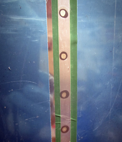
That's the inner faces of the skin showing scuffing complete (and deburring, though that makes no noticeable change) and all the schmutz cleaned off. Not visible is the blue vinyl on the other side of the skin, which has now been removed in stripes along the rivet lines. This means that the skin was ready for dimpling!
I had Jamie come over and we ripped through all the dimpling pretty quickly. Definitely have a friend come over and help with this, because it goes way faster. And definitely don't forget to do one of the lines of #8 dimples while the friend is there somehow, and be forced to do that line solo later. Ask me how I know. Anyway, they're all done now:
I didn't have time tonight to do any actual sealant and riveting work, but I did go ahead and mask off the three parts that get riveted to the inside of the top tank skin:
Those three parts should use up one 10g dose of sealant nicely, with a bit left over to attach a few of the small bits that get attached to the end ribs. But that's for the next post, whenever I get around to it.
21 Oct 2012
I'm making steady progress on getting stuff riveted to the right fuel tank skin. The only trouble is that said progress is quite slow. The fuel cap flange and vent clip are done, as are 10 of the 14 stiffeners and all of the tooling hole fillers in the inboard and outboard ribs.

I should be able to get the last four stiffeners done in a single 10g batch of sealant. After that, it'll be another 10g batch to get all of the various bits and pieces squeezed onto the inboard aft rib, apply the drain fitting, and put the forward inboard rib in place. All of those parts can be squeezed. Those two sealant iterations should be done sometime this week.
Fun fact: the first rivet on the fifth stiffener I installed was the 10,000th rivet in the airplane!
24 Oct 2012
I've now finished all of the bits that I can back-rivet onto the skin, specifically the fuel cap flange, vent clip, and the 14 skin stiffeners. I also went ahead and did the "squeezer pass" which encompassed the drain fitting, the forward inboard rib, and a bunch of the goodies that get riveted to the aft inboard rib. Here's a picture showing the drain fitting and the inboard rib in place:
Ten grams of sealant wasn't quite enough to do all of the fillet and rivet head coverup work on all those parts, largely due to the large amount of sealant required to do the forward fillet on the rib since the rib has bend holes there that have to be covered. I'll have to come back over these parts with some excess sealant at some later date. No problem. I did get one bad rivet on the forward inboard rib which will need to be drilled and replaced, so I guess it's good I didn't cover the back in sealant yet...
The next riveting tasks are the five interior ribs, all of which I'll need help completing.
3 Nov 2012 Robb came by last week and helped me put in one of the interior ribs in the right fuel tank. We had a few problem rivets that had to be drilled out, and Scott came by and helped me fix those up. Scott came by again this weekend and, in a 4-hour marathon, we finished riveting the other four interior ribs.
There is still one bad rivet that has already been drilled out but that I will require assistance with to get re-bucked. Other than that, I've got a bunch of work ahead on this fuel tank that doesn't require assistance. I may bring someone in to help with the J-stiffener install, though I could probably manage by myself. But seeing as I need help getting that one rivet redone, I might as well combine that with having someone speed up the J-stiffener application.
There were three instances during the riveting of the ribs where the bucking bar was dropped onto the skin, two of which left noticeable dents in the skin material. I've purchased a panel beating hammer and a small shot bag so that I can flatten out the dents, but they haven't arrived yet. I won't be able to seal up the aft baffle on the tank until I've taken care of the dents. So there may be a bit of a delay.
4 Nov 2012 I went ahead and squeezed the outboard rib onto the right fuel tank as well as the fuel tank attach bracket. The bracket had to be bucked, but it is reasonably straightforward to do this solo. Here's the bracket in place:
And here's the outboard rib, still needing the big fillet of sealant at the nose bend:
Somehow I managed to put some masking tape on the bracket that ended up between the bracket and the tank skin, and not notice that until I had riveted the pieces together. So now there's some integral tape in my project. I'll put some extra sealant around the inner fillet in this area to make sure the tape isn't a conduit for leaks. <facepalm>
Remaining tasks for the right fuel tank, in the order they must be done:
There are a couple of steps there that are on hold for equipment or tools that I've ordered that havn't shown up yet. Given that the shot back is backordered, if I can't find one to borrow there may be a delay before I can get the aft baffle on this thing. But regardless, progress has been made recently! I'm almost out of the hideous morass that is the fuel tank chapter.
23 Nov 2012 The website has been down for awhile due to the hurricane in NYC where the server was housed, but it is now back.
I've been slowly working on getting all of the internal sealant squared away in preparation for closing up the right tank. I was waiting for the fuel level sender and panel-beating supplies to arrive, and they're all here except for the lead shot. Once I can find some shot and clear out the dent in my skin I'll be ready to put the aft inboard rib in place and close up the right tank for good.
I'm contemplating running the stall warning wires and aux connector video lines from the left outboard leading edge into the wing root forward of the spar. To do this, I'll run wires through the holes in the left tank Z-attach brackets. In preparation for this possibility, I popped some snap bushings into place on the left tank. They look like this:
Also, I ordered all the wires I'll need for wiring up both wings from Stein Air and, on a whim, I wrote "Draw a dragon on the box!" in the order comments field of my online order. This is what arrived:
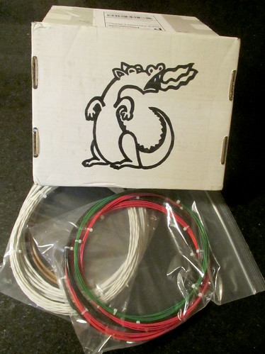
NICE! Way better artisanship than I would have expected. I cut out that side of the box and hung it up in my shop. Stein Air, you have a customer for life (if perhaps for the wrong reasons).
25 Dec 2012
I got the J-stiffener riveted onto the right tank:
I went ahead and installed the snap bushings for the vent tube, then fabricated the vent tube. I haven't installed it yet because I want to finish covering the J-stiffener rivet heads with sealant before I put the tube in the way.
All of the sensors for the aft inboard rib on the right tank have arrived and are ready to be installed, but installation of that part is also on hold pending completion of the sealant on the J-stiffener.
I set up the right tank for an initial pressure test, with a manometer tube on the vent, a plug on the fuel outlet, the fuel cap in place, and a bicycle pump valve on the drain. I pumped the tank up to about 12" of pressure but it only held for a couple hours. I determined that the leak was between the threads on the vent fitting and the manometer tube, so I had to get some vaccum grease to seal it up with. I've now procured the grease but haven't repeated the pressure test yet.
29 Jan 2013
It's been a slow few months in the workshop, there's been a lot going on here outside of plane-building. I just managed to not have to say that nothing was accomplished in January, as I did find the time to fabricate and install the vent tube for the right fuel tank. Check this bad-boy out:
But seriously, that's it for the whole month. Less than an hour's work, 3 new parts, no rivets. :( Hopefully I'll have more time to devote to this in Feburary.
10 Feb 2013
I've been trying to find someone in the area that carries #9 lead shot so that I can get to work on panel-beating the small dents out of the right fuel tank before closing it up. There isn't much left to do on that tank prior to putting the aft baffle on and all of the parts are now here, so I'm basically held up behind fixing the dents.
So this morning I gave up and just ordered some shot from Amazon. Sadly, free Prime shipping was not available. And shipping on a 25 pound bag of lead is... not cheap. But soon I'll have everything I need to finish up the right tank.
In the meantime, I set to work on the second iteration of the left tank leak check. I had done a first round previously, but it turned out that the seal between my vent fitting and the manometer tube was no good so it wasn't much of a test. This time I got some vacuum grease from Bob and smeared it all over the threads to the vent fitting. This kept any air from leaking out and easily held back one PSI.
I used a bike pump and the valve fitting that Van's sells in the drain hole to pressurize the tank up to 1 PSI (~27" of water). I made a soap solution with about 1 Tbsp. of dish soap in a liter of water and put it in a spray bottle and liberally sprayed all rivets and connection joints on the fuel tank while it was pressurized. There was one immediately-obvious leak coming from a pinhole between the aft baffle and the top skin flange.
I wasn't sure how much bubbling I was supposed to be looking for, but this one made large bubbles very quickly so it made me more confident about all the skin rivets and other joints that had no discrenable bubbling at all. The good news is that this leak is A) not on the outer skin and B) in a place that easy to fix. I should be able to just dab some sealant over the pinhole and be done with it.
The only other "leak" I found was a similar one at the plugged fuel outlet fitting. I think this is just because this fitting has no grease in it and the plug isn't perfect. It looks like the bubbles are coming from the threads and now the sealed rivets nearby. I'll check it more carefully when I do the third pressure test of the tank after fixin the pinhole on the aft baffle.
Here's a video showing the basic manometer setup and the bubbling leak:
Although having a leak is worse than not having a leak, I'm glad it's such an easy one to fix.
23 Feb 2013
I finally got my lead shot and was able to panel-beat the small dents in the right tank skin out of existence. That was the big hold up on progress for this tank, so I got a lot done this weekend finally.
In preparation for riveting in the aft inboard rib, I put the finishing bends on the vent line. First, I bent the outboard end up to maximize usable fuel volume in the tank:
At the inboard end, I put the bends necessary for the vent tube to align with the bulkhead fitting without any stress:
Next, I dry-fit the aft inboard rib with the fuel level capacitance probe attached to make sure the bends in the probe were good.
For some reason I bent this one slightly differently than the one in the left tank. This one has the 135° bend aft of the stiffener, which makes it hard to angle the tube up towards the aft upper corner of the second bay. I recommend not doing these the way shown here, and instead bend them the way I did in the left tank which gets a slightly better high end point.
Next on the hit parade was to mask up the aft inboard rib area for riveting.
Because I knew I was going to be doing a round of sealant, and that I needed to put some sealant on the leak on the left tank, I first tried to get some Loctite to wick into the pinhole.
I put this line of blue Loctite across the area that was bubbling during the pressure test, then drew a slight negative pressure on the tank. There was no clear indication that any perceptible volume of Loctite was being drawn into the pinhole. I let it dry for a couple hours then wiped off the bulk of what you can see here. When I mixed the sealant for the right tank aft inboard rib, I put a small line of it across the leak area. Unfortunately, after a few hours I could see a small pinhole in the sealant right where the old leak was. So I'm not sure I've accomplished anything yet. I'll do another line of sealant here when I next mix a batch.
Riveting on the aft inboard rib was straightforward solo as all the skin rivets can be done with a squeezer (though one of them behind the vent bulkhead fitting required a narrow-nose yoke in the squeezer).
I did all of the skin rivets but passed on the attachment bulkhead rivets for now. I also ran out of sealant before I got all of the joints filleted or rivet heads covered. I'll leave it like this for now and do a second batch of 10g of sealant to hopefully finish off the goodies on the inside of the tank and be ready for attaching the aft bulkhead. Just for my own reference, here's what I need to put sealant on before closing up the tank:
28 Feb 2013
In the last couple of days I've gotten the sealant done on the innards of the right fuel tank. I installed the Fuel Guardian sensor and got it sealed in, torqued up the vent line to the bulkhead fitting and sealed it up, sealed up the fuel level sensor, and added standoffs of sealant everywhere where the capacitance probe comes near a metal surface. Finally, I did the six rivets that connect the inboard rib halves to the forward tank attach bracket. Now I have to wait for awhile for the sealant to cure before I do the red water leak test.
Meanwhile, the left tank has that little spot of new sealant over where the leak was, and I want it to cure good and strong before I do another pressure test on it. So both fuel tanks are somewhat out of commission for awhile.
3 Mar 2013
I put the left fuel tank back on the workbench and gave it another pressure test, now that some time has passed since I put sealant over the leaky spot. Much to my satisfaction the leak was gone. So I took my pneumatic squeezer and put in the remaining 20 skin-to-aft-bulkhead rivets (the ones that fill the holes used for alignment during the initial aft bulkhead attachment). Since there wasn't any leaks prior to adding these rivets, I didn't use sealant on them. But just to be sure, I went back and pressure tested the tank one more time. Unfortunately, somewhere during this process I seem to have opened up a second leak right at the upper-outboard corner. It doesn't seem to be associated with the rivet that I just added there, but there is a very slight leak coming out of the aft and side on that corner.
It is a very slow leak, at least twice as slow as the previous leak, and it is at the very highest point in the tank (where fuel will never be except during sloshes), but I am going to seal it up anyway. I already dried all the soapy water off the area and added some Loctite under slight negative pressure. I'll let that dry for now and turn my attention to the other tank. When I get to the next sealant mix on the right tank, I'll add a little dab here to finalize it (hopefully).
10 Mar 2013
A weekend that was meant to be spent on a snowboarding holiday was instead spent terribly ill and doing leak checks on a fuel tank.
This is essentially a reapeat of the "Kool-Aid" test that I did on the left tank, but this time on the nearly-complete right tank. The first step was to get toilet paper taped over all of the rivet lines. Looks something like this:

Then I went to the store to stock up on cold medicine and red food coloring. Here's what 27.5 gallons of very red water looks like in the tank:
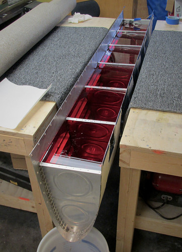
Again, I'm using carpet draped between two work benches as support for the tank. Works like a charm. I tilted the tank slightly in the outboard-down direction, so I wasn't able to get a full 30 gallons in. That water line is right up to within a milimeter or so of the top of the outboard rib, but there is still 1.5" or so of inboard rib above water (hooray for mixed units!).
I let the water sit at maximum for awhile and did spot a couple of immediate leaks. The bigger of the two was at the junction between the skin, forward wing attach bracket, and inboard aft rib:
It's actually coming out from three places: the forward and aft sides of the small tab on the rib (but not the inboard side), and from the larger unpopulated hole visible here which goes through the skin and bracket. It isn't clear to me if the water coming out of the hole is actually wicking down there from the aft leak around the small tab, or if there is actually a hole going all the way between the skin and bracket to the inside of the tank. It doesn't really matter; I'll fix this leak internally with a liberal coating of sealant in this corner. Shouldn't be an issue.
If the leak persists after I close up the tank, I can remedy any leaking around the little tab quite easily. If it's still coming out the screw hole, that's going to be a bit more dicey. I'll have to hope that the Loctite trick will work.
The smaller of the two leaks I found was a very slow seep around the bulkhead penetration for the fuel level probe:

Again, this should be straightforward to fix internally, and can be fixed externally if need be after the tank is fully sealed. Not a problem.
I made a bit of a mess because the tank was so full and ended up getting some water drips over the outside, which got onto my TP litmus system, but I'm pretty sure I'm good on all the skin rivets. There was one spot where I couldn't tell if it was a seeping rivet or a spilled drip:
So I'm going to treat the closest rivet to that red spot as suspect and give it Loctite and then additional sealant.
Overall, a lot more problem areas than on the last tank (where there were none), but this isn't entirely surprising since I never did an external sealant pass on the inboard and outboard ribs. I have to let all of the water that has wicked into the nooks and crannies dry out before I hit the right tank with sealant again, so it'll probably be another week before anything happens here. But I should be able to get the aft baffle on before too long here.
17 Mar 2013
Spent some time on the fuel tanks this weekend. First, I sealed up the new leak that appeared in the last pressure test on the left tank. For good measure, I also put a second coat on the seal of the first leak. I'll let that tank sit for a week or two and then give it another pressure test.
On the right tank, I did a final 10 gram batch of sealant to cover up all of the areas that failed the Kool-Aid test last weekend. This included the junction of the bottom skin, forward attach bracket, and aft inboard rib (both inside the tank and outside), as well as additional sealant around both the inside and outside junctions between the fuel sensors and the rib.
I'm confident that I have plugged the holes that led to the failed pressure test, so I'm declaring this tank ready for its aft baffle. Even if I'm wrong on that assumption, I can add additional sealant from outside the closed tank to these areas without a problem.
The aft baffle will require the bulk of my remaining sealant (I'm still on my first can!) and about 4 hours to complete, if the last tank is a good estimator. I may have time for that sometime this week, otherwise it'll happen next weekend. Then I'll have two sealed tanks!
1 Apr 2013
Yesterday and today I finally put the aft baffle in place on the right fuel tank.
I did one last inspection of the interior surfaces, then gave everything a good wipe-down with acetone to get all the fingerprints, dust, cat hair, etc. out of the tank. Then I masked off the bits of skin that extend aft of the baffle, mixed up 40 grams of sealant, and went to work covering all of the rib aft flanges and the skin/baffle contact area.
With the sealant in place, I lowered the baffle into position and went to work adding the huge number of clecos it takes to fill every hole. The first part to be riveted was the middle five Z-brackets, which get pop-riveted in place with sealed-end blind rivets. Then, I started the seemingly endless task of riveting the skin to the baffle. Here's a shot after just 15 skin/baffle rivets:
I managed to get one side of the skin/baffle rivets done before I ran out of sealant and had to take a break. I returned this afternoon to finish off the two remaining Z-brackets and the other side of the skin/baffle rivets. This took less than 10g of additional sealant.
Now the right tank is essentially complete, structurally speaking. Once the sealant cures, I still have to pressure test it and countersink/rivet the 20 pilot holes. Then the right and left tank will be in the same state. When they're both pressure tested to my satisfaction, I'll prime the outer surfaces that aren't skin, rivet on the attach bracket spacers, and the fuel tanks will be done done.
24 Apr 2013
This month has been mostly consumed with waiting for sealant to cure on the fuel tanks. Between the aft baffle of the right tank and the second leak in the left tank, both tanks were out of commission curing for the last three weeks.
I was somewhat dismayed to find that, when I pressure-tested the left tank this weekend, the first and second leaks were sealed properly but now there is in fact a third leak between the aft baffle and the skin. It's the smallest and slowest of the three thus far, but it means another cycle of proseal and curing.
However, there is good news as well. I put the right tank on the pressure tester for its first go and it passed with flying colors! I pumped it up to one PSI and let it sit for three days. There was no drop in pressure at all. No bubbles anywhere when soaked down with soapy water, etc. Perfect! The moral of this story is to use 40g of sealant when doing the aft baffle, which I did on the right tank, instead of 30g which is what I used on the left tank. ++sealant is good.
Having declared the right fuel tank fully-sealed, I took a bit of time to countersink the 20 guide holes between the aft baffle and the skin and install the final skin rivets. Next, I started preparations for the next phase which is to prime the aft and sides. First, I cut off the fingers of a nitrile glove and use them to cover the fittings on the vent and fuel outlet. I held the glove fingertips in place with rubberbands.
I also added the fuel drain valve (just finger-tight for now). Next I'll cover up the sensor wires, mask-off the outer skin, and the assembly will be ready for priming. I may wait until the left tank is finally done so that I can do both priming steps at once.
11 May 2013
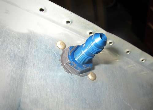
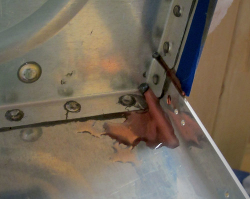
While waiting for the sealant on the third leak in the left fuel tank to dry, I took a look at the fuel drain fitting. Here it is in its natural state:
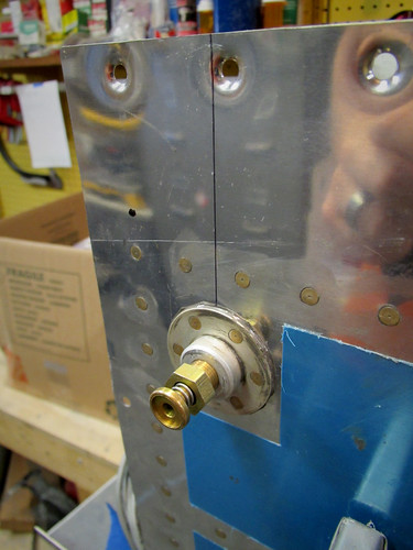
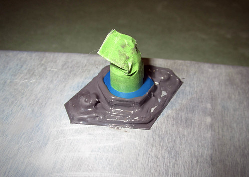
It sticks out about 1.5" from the bottom skin and strikes me as unsightly, so I got a pair of drain fitting fairings from Aircraft Extras. Here's a picture of one in place:
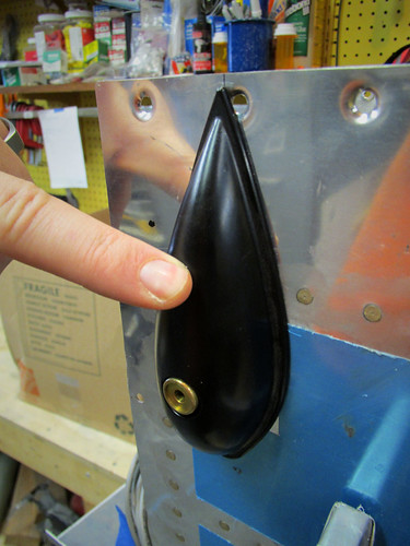
It does a good job of covering up the drain fitting in a aerodynamic and visually more-pleasant way. The training point of it does cover up one of the tank attachment screw holes slightly, but this can be ameliorated by trimming the fairing flange a bit. The real problem with this fairing is that there is very little clearance between the drain flange and the fairing, meaning that there is no way to adjust or inspect the drain fitting once the fairing is installed. The only way to install the fairing is to seal it onto the skin with something like ProSeal. Any need to inspect or adjust the fitting (e.g. if it begins to leak) will require prying the fairing off. So the question becomes, when do I paint? My intuition tells me to paint the tank skin and fairing separately before attaching the fairing, then seal the fairing in place and touch up the sealant joint with some paint. I'm hoping to find examples of other builders who have used these but so far have come up blank.
Once the sealant leak #3 had dried I re-pressurized the tank and... I suppose I shouldn't be surprised...
Leak #4. This one is extremely slow. I am getting pretty tired of sealing these damn things. I was trying to figure out why I only ever see one leak at a time, and then, having sealed it, a new one opens up. My best guess is that these pinhole leaks have thin membranes of sealant covering them, and when I pump the tank up I get enough pressure to burst the weakest one and then it acts as a pressure relief valve, preventing the other weak points from becoming apparent. Not sure. But I think if I find another leak next time around I'm just going to mix up a bunch of sealant and put a bead along this whole joint and hopefully be done with it forever.
Time to wait for another couple weeks for the new sealant to dry...
31 May 2013
So I let leak #4 sit with fresh sealant on it for a couple weeks and re-pressurized the tank. I should probably just cut and paste an old entry here, because predictably this happened:
So I've had enough of spot-fixing these leaks. I have no idea why there are so many. So I just said F it and mixed up 10 grams of ProSeal and put a fillet along the entire joint between the skin and baffle. I probably should have done this a few leaks ago, but here it is.
I'm going to let that sit for a long time since I'm off to Alaska for a couple weeks before this will cure. This of course means that the June progress on the RV-10 will be somewhat sparse... but I'm sure you used to that at this point, what with all the waiting for leak sealant to cure... Ugh.
29 June 2013
Apparently this is a one-update month. I did some basic looking ahead and determination of dependencies—which parts need to be worked on in which order, which assemblies need to be finished first in order to make room for others, etc. Basically, everything is log-jammed behind getting the left fuel tank sealed, and the leaks keep appearing. By my count, I am now up to 7 leaks, two of which appeared after I added the huge fillet of sealant around the entire skin/aft baffle joint. Ugh. To be fair, I was in Alaska for half of this month... so I've had less time to work on the plane that I could have.
After letting the massive fillet dry while in Alaska, I came back and pressurized the tank (again) to find this little seep:
It's one of the rivets that attaches the baffle to the skin, so both sides were accessible (thank goodness). The leak was only coming out the skin side. I drilled the rivet out and put red Loctite around the hole to let it seep into the joint between the skin and baffle. This was over a week ago. Today I pumped the tank up again to see if the Loctite would hole the leak, which it seemed to be doing nicely. No leakage detected at this rivet hole at all, despite the lack of a rivet. However, I was still losing pressure... so I did a full soak in soapy water of the whole tank again.
This time, a small pinhole in the massive fillet was giving off air. GAAAH!! So I've now gone through and dried off all the soapy water, and gone over the fillet with a flashlight looking for pinholes, including those that don't appear to be leaking. Tomorrow, when any remaining water in there should have evaporated off, I'll put Loctite in all of the pinholes I can find, and give that a day or two to cure. Then I'll do another small batch of sealant and cover all of the pinholes with sealant... and that of course will take a couple weeks to cure. So get ready for an uneventful first half of July on this construction log...
20 July 2013
Here is the best picture ever.
That is the water meniscus in my manometer monitoring air pressure in the right fuel tank. I have been fighting leaks in that tank for many months now. Finally, this time the tank held pressure for hours with no sign of a leak. So the sealing of the right fuel tank is COMPLETE! Yes!
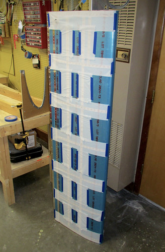
With that out of the way, I added the drain fitting, finger strainer, and fuel cap and set about masking off the skin and fittings so I could prime all of the external surfaces of the tank that aren't visible in the fully-assembled plane. Most people don't do this step, but I figured why not... I've spent so much time on these tanks I might as well add some primer, and it doesn't take much time. Here's one of the tanks all masked up:
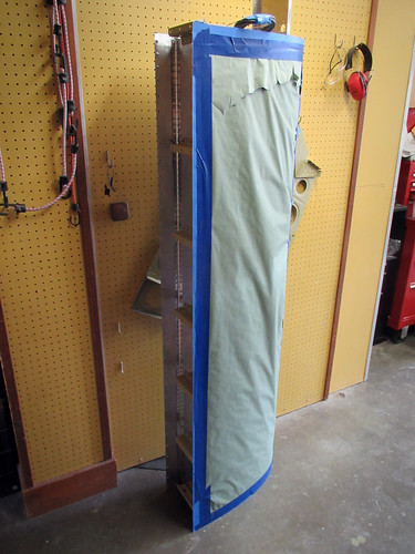
The weather turned rainy in the afternoon so I wasn't able to actually do the priming today, but soon!
21 July 2013
Today the weather was good so I pulled the fuel tanks out into the driveway and primed the necessary bits. Here's a picture of the results:
As you can see here, once the primer was in place I riveted on the torque tube bearing, shims, and nutplates on the forward attach bracket, rendering the fuel tank subassemblies complete! This is only slightly a lie; my cat seems to have run off with one of the bearings, so only the right tank is complete. The other tank is awaiting shipment of a new bearing before the last few rivets will be emplaced.
3 Aug 2013
I hadn't quite been able to finish both fuel tanks because I seemed to be missing a VA-146 bearing for the left forward attach bracket. I ordered a replacement and it has now arrived, so tonight I put the last few accessories into the left fuel tank. These included the aforementioned bearing as well as the shim plates and nutplates on the attach bracket flanges. Additionally, I put snap bushings into the lower hole in each of the Z attach brackets to allow for a wire harness to connect the inboard bay of the left leading edge to the wing root.
All of the holes in the inboard fuel tank rib are covered with nitrile glove fingers and rubberbanded to keep bugs and dust out of the tank. The tank is now officially done aside from painting the skin, and has been moved into the garage for storage until the left wing is ready to have it attached.
Time invested on this sub-assembly: 129 hours (111 by me)
Updates regarding the fuel tanks
12 Jun 2011I started work on the fuel tanks awhile back in January when I did the primer pass for the leading edges. I knew that most of the fuel tanks don't get primer (until after they're assembled and sealed, if at all), but that the Z attach brackets could be primed as they were external to the tank proper. So I did a very small amount of work to get them match-drilled to the rear tank baffles and then threw them in with the parts to be primed. I did forget to countersink the nutplate attach rivet holes, though, so now those countersinks are bright silver on otherwise green pieces.
With the countersinks cut, I went ahead and riveted on the nutplates, rendering the brackets complete. These are the last thing that gets attached to the fuel tanks per the plans, but are the first parts completed. Go figure.
The next step was to cut out all of the tank skin stiffeners and the vent line clips. I made relatively quick work of these with my snips.
Once all of those were done, it was time for the initial assembly of the fuel tank. I started with the left-side tank. First the stiffeners went into the skin:
Then the ribs go in. For some reason this was really difficult. I had a really hard time getting the holes to line up and it took forever. But they did eventually all go in.
Having to stuggle to get a lot of those clecos in led to my hands hurting a lot and being blistered, so Jeremy helped with the cleco pliers while I match drilled all of the holes.
The last bit of work I did on the tanks today was to figure out where I was going to mount the fuel level sensor. I don't like the inelegant float-style sensors that Van's recommends; I want to go with a capacitance sender. The trouble with them is that the sensitive region has to be straight, so you need to find a straight line within the tank that doesn't touch anything metal and goes from as low a point as possible to as high a point as possible. The best I could do was this span from the lower-inboard edge of the inboard bay to the upper-outboard-aft corner of the second bay:
This span is about 24" long, which is conveniently the maximum length they make these probes in, and covers most of the height span of fuel in the tank. When the top of the sensor is covered in fuel, there'll be a few gallons space left in the tank, so I'll have to burn a few gallons of fuel before I start seeing a change in my fuel level readout in the cockpit, but that's not problem. Below the bottom edge is probably just a gallon or two, so empty on the gauge will be a reasonably accurate figure.
18 Jun 2011
This week I got the left fuel tank up to the point of having to wait for parts I've purchased that haven't come in yet. Specifically, I got the aft baffle match-drilled as well as all of the Z-attach brackets.
In addition to match-drilling all of these holes, I also did the countersinking of the baffle-to-skin hole lines.
These are somewhat unique thus far in the project as they are the first skin holes that get countersunk instead of dimpled. I gather that this is done because once the rest of the tank is assembled and sealed, it would be very difficult to get the aft baffle in place past all the dimples when there is also a slathering of proseal in the way. Anyway, it's done.
The only remaining steps on the left fuel tank prior to "disassemble the whole thing" are to fit the fuel cap flange and the fuel level sensor. I've put in an order for the fuel level sensor, but it is a made-to-order part and hasn't shipped yet, so that's on hurry-up-and-wait status. As for the fuel cap, I'm somewhat underwhelmed by the ones that Van's sent with the kits, and I'm considering shelling out the extra money for the machine-contoured locking versions that are really nice. Pricey, but not absurdly so. And since I'm likely to have a sizeable financial hiatus after the wings are complete... what's another couple hundred bucks?
In the meantime while I'm waiting for these parts, I've put the left tank back into storage and started on the right tank. I didn't get very far, just got the vinyl pulled off the inside of the skin, verified that the edges were deburred (when did I do this??), and cleco'd the stiffeners and fuel drain fitting in place.
22 Jun 2011
Over the last few days I've gotten the right-side fuel tank up to the same point the left-side tank is at, which is to say bottlenecked behind the pending arrival of my locking fuel caps and capacitive fuel senders. The fuel caps are already on their way, no word on the senders yet. Anyway, the fuel tanks are both on standby for the time being.
8 Jul 2011
I put some bends in the fuel level sender probe that showed up earlier this week to test for fit. It seems to be perfect.
I am a little let down that the kit didn't include the nut and lockwasher that will be needed to secure the probe to the tank rib... but I can get that at the hardware store, I suppose.
16 Jul 2011
My locking fuel caps showed up awhile ago, but I seem to have neglected to talk about them here. They are a huge improvement over the stock fuel caps, even if you have no intention of locking your caps I suggest buying these. The mechanism and build quality are vastly superior in every way.
However, they do suffer from one of the same problems as the stock caps—the flanges are contoured to the wrong curvature for the RV-10 tank skin. When I hold my flange in place, the forward and aft edges are not flush at all.
I wasn't sure if the lack of flushness was entirely due to the part being the wrong shape, or if some of it was because the tank skin wasn't fully curved without the aft baffle in place. I went ahead and drilled the holes into the right-side fuel cap flange and cleco'd it into place along with all of the adjacent hardware (including the aft baffle) to see how bad the contour fit was.
It was pretty terrible. The thin edges (forward and aft) were still standing off from the skin by many millimeters. What I needed to do was to sand down the outer contoured face of the flange to get some of the thickness off so that it would better match the skin. Unfortunately, I don't have the appropriate tool for that. In fact, I had marked several parts that needed tools I lacked for fabrication, including the fuel cap flanges, the fuel level sender access port covers, and several pieces of tube stock for aileron actuation. Last week I had a chance to run over to Pat Turner's shop with Bob and we did some quick fabrication work on these parts.
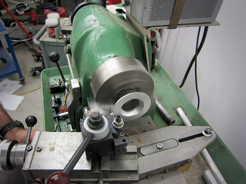
First, we cut the main aileron pushrods to length as well as the small steel pushrods that connect the aileron itself to the bellcrank in the wing. Next, we loaded the fuel cap flanges into a lathe and turned off about half the thickness of the highest parts.
The result was a flat section across the middle side-to-side, and a bit of contouring reamining on the forward and aft edges.
The next step will be to sand some curvature back into the central part of the flange with a belt sander, but I wanted to test fit these first to make sure it was helping. Turns out it needs a bit more taken off before the curvature is applied. But it is a lot better than it was!
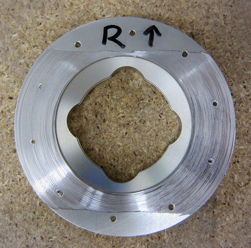
The last thing we did at Pat's shop was to cut out some covers for the fuel level sender holes in the tanks. I had ordered the T-411 parts from Van's, but unfotunately they are for all Van's aircraft models except the RV-10. They advised me to send them back and just fabricate my own; I skipped the first part and just used the T-411s as stock for my custom ones. Having access to a CNC mill at Pat's shop, we cut out perfect 2.65" diameter circles.
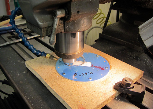
Once the circles were cut, I clamped them into place on the fuel tank inboard rib and drilled out the screw holes.
Notice that in this picture the cover plate is inside the tank; this is just for ease of match-drilling the holes. The plate will be screwed onto the exterior of the tank during final assembly.
8 Aug 2011
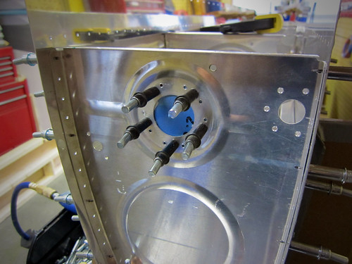
I selected a location for the Aircraft Extras Fuel Guardian sensors that I purchased last year. The nut on the sensor head fits perfectly in the anti-rotation plates used on the fuel vent fitting, so I'm going to order a couple extras to use with the Guardians. Unfortunately, making room for the anti-rotation plate limits the places I could locate the sensor. I decided to go for a relatively low position, which in turn limits the time between when the sensor will go off and when the tank will run dry.
As you can see, the distance from the sensor head to the fuel intake is not much. Just a couple inches. I estimate this'll give me about a 10 minute warning on fuel. That's not a whole lot, but I'm intending for the Fuel Guardian to be a redundant backup to the EFIS' fuel level monitoring anyway, so I'm OK with that. If I'm approaching a fuel-exhaustion event, the FG light will come on and I'll have to land immediately. Or, more likely, just switch tanks (and then land).
3 September 2011
It's been a long time coming, but the fuel inlet flanges are finally conformal with the curvature of the skin.
I've been using a belt sander to grind off some of the exaggerated curvatore these locking fuel caps came with, but I didn't want to go too far, so it has been a process of many iterations. Unfortunately, I didn't have a belt sander so this involved taking them in to work for about 30 seconds of work, then back home, test fit, rinse, repeat. This weekend I broke down and bought my own belt sander, which I love already, and finished the job. It still took a long time and I almost burned my thumb on hot aluminum, but they now fit beautifully.
This was the only thing holding me up from disassembling the fuel tanks, which I proceeded to do immediately. I had previously drawn outlines around all of the contact surfaces on the skins so I know where to scuff prior to dimpling, and this was my first chance to see them all:
This should help keep the alclad coating intact wherever possible. The last thing I did tonight was clone the holes for the custom fuel tank accessories (fuel guardian sensor head and capacitance fuel level sender) into the inboard rib for the left tank. Having already figured out where everything should go and what size holes were needed on the right tank awhile back, this was a reasonably quick operation.
3 Mar 2012
Fuel tank finaly assembly has begun!
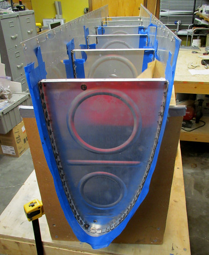
I grabbed the left fuel tank skin and deburred it inside and out. The edges were already deburred for some reason, so I moved right ahead with removing the vinyl lines. The last thing to do was to scuff all of the places where two pieces contact each other. For the most part this just meant masking off the lines I had drawn last time the tank was assembled and rubbing the rivet lines with Scotchbrite. The fuel fill flange and drain required a bit of fancy masking...
OK, that was probably overkill... but the resulting scuff ring looks very nice and circular. Too bad no one will ever see it once I button the tank up.
The last thing I did before dimpling was to give the inner tank surface a thorough cleaning with acetone. I wanted to make sure I got all of the metal dust from the Scotchbrite off of there, along with any finger oils, etc. that might prevent the Pro Seal from sticking as well as it might. I invited Jamie over this weekend to lend a hand supporting the tank skin while I operated the DRDT-2 dimpler with the special tank dimple dies. We worked through the entire skin in just over half an hour, then it was time for working with Pro Seal. Let the fun begin.
I took a cue from Mike Howe's project and used Easy Mask combination tape/paper to make a protected area around each piece so that over splatter from the inevitable thin strings of Pro Seal that go everywhere wouldn't turn my inner surface into some kind of Jackson Pollock tribute. It worked great.
I used a $25 kitchen scale purchased from Amazon to measure out 20 grams of the white sealant compound, then an additional 2 grams of the black accelerant. I used some super high tech stuff to mix it, namely a plastic knife and a paper soup bowl. It smelled exactly like everyone had described, which is to say quite awful. Not wanting to waste the 45-60 minutes of set time, I set right to work on the tank skin stiffeners. I'm glad I spent as much time laying out everything I might need beforehand, as those 45 minutes went by really quick. I put a healthy coating of Pro Seal on the contact face of the stiffener, cleco'd it into place, then added one rivet at a time after putting a little dab of Pro Seal on the end of each one. Once all the rivets were in place, I put some rivet tape over them so that the excess sealant wouldn't get all over my back riveting plate. The back riveting process got sealant all over my rivet set, which had to be cleaned off with a paper towel after each set of three rivets lest it clog up the spring-loaded sheath on the set. Fun times.
Above you can see the Easy Mask paper as well as a couple pieces of blue painter's tape that I used to keep pro seal off of the vertical part of the stiffener. Once I had done all of the back riveting, I went around the edge of the stiffener/skin joint and made a good fillet of Pro Seal with my plastic knife. Then I took a dollup of Pro Seal to each of the rivet shop heads. In this way, none of the interfaces between parts or parts and rivets were visible. Just lots and lots of sealant. Here's a closeup:
I wasn't sure how long to wait to remove the masking once I was happy with the state of the sealant, so I tried just removing the first one immediately. It worked great; no need to wait. Here's the result:
Here's what the shop head on the first set of rivets looked like before I removed the rivet tape:
That's actually a lot more excess than on later rivets. I got a system worked out where I would have just enough sealant on the outer side to be visible around the rivets but not huge rings like this. Each time I finished a stiffener, I'd stand the skin up on its side, take the rivet tape off, and wipe off all of this excess sealant with a paper towel. It wasn't too difficult since the Pro Seal hadn't set yet. The resulting rivet lines look great. Just a hint of a sealant ring around some of them.
And just for kicks, here's one more view of a couple complete stiffeners as seen from the inside:
So here's some notes for anyone else reaching this stage: 20 + 2 grams of Pro Seal was too much; I wasn't able to use it all before it hardened up. I think I probably could have done four stiffeners with that much if I had been careful, but by the time I finished my third stiffener the sealant was getting noticeably difficult to work with. I recommend going with 10 grams of sealant and 1 gram of accelerant at a time and try to get two stiffeners done with that much. Do the dollups on the top of the rivet heads last as they can be done later if you run out of a batch.
Three stiffeners using the techniques described above took me about an hour. The tank assembly is clearly going to be a long process; but I'm excited to be doing final assembly again!
6 Mar 2012
The Pro Seal Fiesta marches onwards.
I'm still working on getting all of the stiffeners riveted to the left fuel tank. I've got 12 of 14 done. I've found that mixing 10g of white sealant with 1g of black accelerant gives me plenty for two stiffeners and then a dollup left over to do some of the other accessories. Rather than bore you with pictures of each identical stiffener as I add them, here are some of the accessories that I've gotten mounted. First up, the fuel drain flange on the bottom-inboard-aft corner of the skin:
I made sure that all of the rivets had a ring of sealant around them when squeezed (I've since wiped it away on this side) and that the flange itself has a good fillet of sealant around its outer edge where it contacts the skin. On the inside, it looks like this:
Here, I put a large dollup of sealant on each rivet's shop head to make sure ther were no leaks around the rivets themselves. I also made sure that there was a good fillet of sealant between the skin and flange inside the hole, but that sealant didn't get onto the threads.
The next thing I did was to attack the tooling holes in the inboard and outboard ribs. The plans call for fabricating a small plate and riveting/sealing it in place, but I figured why not just fill the holes with appropriately-sized rivets? I had some AN470AD6-7 rivets laying around from something else and they fill the holes perfectly. I just coated the shaft of each rivet with sealant and then pounded them into place.
There was a big ring of sealant around the machine head of the rivet after I got it set, which I wiped away before this picture was taken. I just wanted to make sure that there was a thin layer of sealant between the machine head flange and the rib web. On the shop head side, I just covered the whole thing in a bunch of sealant (masked nicely with tape).
The -7 rivet is way too long for just going through this piece of skin, but in this case it is not structural at all and just needs to set enough to hold firmly in place. There are two of these on the outboard fuel tank rib, two on the inboard nose rib, and two on the inboard aft rib.
Next up was the fuel pickup flange, which was basically the same idea as the fuel drain flange. After that I did the inspection cover. I'm using capacitance fuel level probes, so I don't need the floats that usually mount through the inspection port. Instead, I just fabricated a port cover plate and semi-permanently installed it.
Technically it'll be removable, but it's got a ton of sealant holding it on. Plus, I'm going to cover the screw heads in sealant as well as all of the nutplates and exposed threads on the inside. So getting this cover off will be a real chore. Hopefully, it'll never have to happen. Here's a view of the inside as it stands now, without the sealant applied to the nutplates and screws:
That's as far as I got tonight. Somewhere on the 12th skin stiffener was the 7,000th rivet in the plane! What's left prior to rib installation in the skin is:
- two remaining skin stiffeners
- two T-1010 anti-rotation plates in the inboard aft rib
- one more tooling hole rivet
- fuel fill flange and vent line clip
10 Mar 2012
Still slowly progressing through the left fuel tank final assembly. Got all of the stiffeners installed as well as the fuel cap flange and all of the bits that rivet onto the aft inboard rib. Here's the fuel cap flange:
I think the outside looks great; all of the rivets came out well and the thin fillet of sealant between the skin and the flange is perfect. Here's a shot of the inside, showing the installed vent line clip and all of the sealant fillets and rivet head coverings:
There were numerous instances on all parts where I had made a fillet of sealant connecting the part to the skin, only to have a bubble pop in the sealant overnight and leave something that looked like this:
I can't be certain tha some of these voids won't allow leaks (and there were a couple on the aft inboard rib where I could see light coming through them, so obviously leaky there...). I had to go around and mark all of them, then hit them with a dab of sealant in the next batch. At this point I'm pretty sure that all of the bubbles in the stiffeners, aft inboard rib, and fuel cap flange have been taken care of. It's going to be hard to inspect for these once I get the ribs in, so I'm going to start using more sealant around the edges to guard against this.
Speaking of ribs, everything else was done so it was time to move on to the first of the ribs—the forward inboard rib. Here's a shot of it in progress, just after getting all of the rivets squeezed and starting to lay on the sealant:
Because this is an outer surface of the fuel tank, I put an extra huge coating of sealant on the holes at the forward bend in the rib. I also used quite a bit of sealant in the fillet on the inner surface. Here's the inner fillet:
Despite using tons of sealant along this edge, on both sides, I still managed to allow one of the holes to open up and require a touch-up.
Jeremy was avaialble early this afternoon so we set about installing the first full rib. It went pretty well, with no significant problems.
Between the pre-installationg cleaning of parts, the masking of the skin and rib, the mixing and distribution of sealant, the riveting, and all of the cleanup, installing this one part took about 2.5 hours. Only an hour of that was riveting. So the overhead on fuel tank assembly is pretty severe. Here's a picture of the other side of that rib with the very nice-looking fillet around the edge:
I'm going through paper towels and nitrile gloves at an astounding rate, but so far I'm pretty happy with my progress and feel reasonably confident that I won't have any leaks from the parts I've done thus far. Five more full-sized ribs and the aft half of the inboard rib to go...
23 Mar 2012
Getting help with bucking for the interior bits of the fuel tanks turns out to be difficult, so progress has been a lot slower than I'd hoped on the left fuel tank. I'm up to three of the five interior ribs done now. I had some spare Pro Seal on the rib that got done tonight so I used it to install the tank vent fitting and nut in the inboard rib. Here's how it looks on the outside:
And here's how it looks on the inside:
The outer end of the fitting will be used to attach a manometer during the tank leak check, but otherwise will not be touched again until the wings are attached to the fuselage, which is a long way off.
The inner side of the fitting gets attached to the vent tube, so I went ahead and cut a piece of soft aluminum tubing to length, straightened it, and used my new flaring tool to give it a nice 37° flare. Here is the result:
Flaring is super easy and I was very happy with the results. This tube assembly now gets set aside until I've finished all of the tank ribs and the J-stiffener.
While waiting for shop assistance to be available for bucking the ribs, I've been finding a few other odds and ends to work on.
For starters, I finally figured out the right hardware to attach the Princeton capacitance fuel probes to the fueltank rib with. Why they don't ship with it is a mystery to me, but whatever. The answer is a brass 1/4" NPT compression fitting nut which McMaster Carr sells for under a dollar. For those familiar with compression fittings, note that you do not need the sleeve; just the nut. I did run into a problem with the fuel probe that I had already test-fit, because where I had bent it, it was now slightly larger in one dimension than 0.25" and the tolerance on the hole in the compression fitting nut is quite close.
The solution was just to drill out the hole in the nut to 0.29", which is what the widest part of the bends ended up being. I'm not counting on the compression fitting for a good seal (everything will be coated with Pro Seal on the inside anyway), so the added gap around the tubing when secured shouldn't be an issue. There's still plenty of shoulder on the nut to make tight against the fuel probe.
30 Mar 2012
I had bronchitis there for a week or so, and as a result not a lot of work got done. But a few things did happen here and there.
For one thing, I did manage to get all of the ribs installed in the left fuel tank:
I ended up doing a couple passes of touch-ups with Pro Seal to make sure there weren't any bubbles or pinholes in the fillets around the ribs, so I'm reasonably confident at this point that there won't be any leaks from the rivets I've put in thus far.
I got Jeremy to help me put the J-stiffener in as well. It was somewhat of a challenge to do the forward fillet behind the curl of the stiffener. I ended up just putting a blob of sealant on my (gloved) finger and sticking it up underneath the stiffener. Then I'd go back with a popsicle stick and try to smooth it out, blind. Finally, I'd have a look with a mirror and a flashlight to see how I did. I probably went a bit heavy with the sealant here which made it a lot easier. Here's a shot of the inboard bay with the J-stiffener installed.
Also visible is the installed vent tube. This was trivial to do, since it just involves 6 snap bushings and the already-fabricated tube. The hand-bend in the outboard bay to line up with the vent clip was trivial, and I expect the bend in the inboard bay to line up with the bulkhead union to be similarly easy. Once I get the inboard aft rib installed, I'll hit each of the snap bushing/tube/rib intersections with a bit of Pro Seal to keep it from vibrating around too much.
The whole reason I put aside the work on the main body of the wing and started assembling this fuel tank was because it was cold out and I wanted to do the chemistry phase of the main body work outside if I could. This weekend's forecast is for great weather and warm temps, so I may shelve the fuel tank for awhile and go back to working on the rest of the wing.
9 Sep 2012
Pulled the nearly-complete left fuel tank back out of the garage now that the shop was clear of other wing parts, and worked on getting the fuel tank attach bracket riveted in. This was the first bit of fuel tank sealant work that I did solo, and it really slows things down. My advice to other builders is to have an assistant whenever you can find one for ProSeal work.
Step one was to put the part in place and mask off all of the areas I wanted to make sure didn't get ProSeal all over them. The pre-taped masking paper worked wonders in the forward end of the bay (below the bracket in the photo above). The tape also helped remind me not to apply sealant or rivets to the holes that are shared by the aft inboard tank rib which will be installed later.
Next I removed the part and cleaned it with acetone. I mixed up one 10g batch of ProSeal and applied it to the sides of the bracket as well as the aft side of the forward inboard rib flange.
The riveting was straightforward, even solo. Because it is the open end of the fuel tank, the reaches aren't terribly awkward and good control of the rivet gun was relatively straightforward. The initial 10g of ProSeal covered the mating surfaces and the caps for all 20 rivet shop heads. I mixed up a second 10g batch to cover a few small pinholes I had discovered elsewhere in the fuel tank sealant joints and to do the fillets around the edges of the tank attach bracket. The underside is a trick because the fillet has to be done blind. This meant just using a (gloved) finger with a big blob of sealant on it to smear it in there. Luckily, no one will ever see that.
With that done I did a thorough inspection of all sealed surfaces and fillets with a mirror-on-a-stick and a flashlight and discovered a number of additional cracks and pinholes that I wasn't happy with so I decided to make a third 10g batch of sealant to fill them. I used the excess to do a second go on the underside fillets of the tank attach bracket since it was difficult to do any meaningful spot touch-ups there. It's a mess under there now, and there's way more sealant there than ideal... but it probably won't have any problems with leaks and that's what I care about most.
Only two major pieces of the fuel tank body left, the aft inboard tank rib and the aft baffle. The rib is the next part but it will take some prep because it needs to have all the fuel sensors attached to it first.
16 Sep 2012
My parents were in town for the weekend so my dad helped me get the inboard aft rib installed on the left fuel tank.
Prior to installing the rib I had to finalize the shape and position of the Princeton capacitance fuel probe. I had one that I had previously bent into position but I had had to un-bend it to get the compression fitting on. When I went to re-position the tube into its original bend positions, the tube failed and broke into two pieces. So I'm going to need to order a replacement there. My advice to anyone using these probes is to only bend them once. For RV-10 builders, you can attach the tube straight onto the rib prior to intalling it, go ahead and torque down the compression fitting, then bend it into position, and finally do the install of the rib without having to modify the bends at all. Do that, and you won't risk a repetitive stress failure of the aluminum like I did. Also, you'll save yourself $200, like I didn't.
Anyway, the bends that you'll want to put into the 24" probe with a 5" bend region at the base is to go 90° down immediately after the compression fitting. Just before the tube reaches the bottom skin, bend it back up at about 135° (see photo, below). Clock the bends such that the tight 135° bend is just forward of the aft-most stiffener in the first bay of the fuel tank. Doing this allowed my probe to pass through the aft hole in the second rib without any risk of touching the sides. I also was not at risk of the probe touching the skin stiffener, so it is only sealant-separated from the fuel tank body at the far (upper) end.
I used a small piece of plastic to hold the upper end of the probe away from the skin, then coated the whole thing with sealant to hold it in place on the skin, being careful not to plug the open end of the probe.
Here's the outside view of the inboard aft rib with the electrical connections in place:
I went ahead and put the final bends in the vent tube and connect it to the bulkhead union fitting. Both sides of the union were coated in sealant since it never needs to be adjusted again. I sealed up all the bulkhead joints on the Aircraft Extras Fuel Guardian sensor and the fuel level probe, both inside and out.
The next step will be to install the aft bulkhead which essentially completes the fuel tank, assuming no leaks. However, before I close it up I'm going to have my EAA technical advisor come by and look at it.
23 Sep 2012
My EAA technical advisor came by last week to look inside the fuel tank before I sealed it up and he liked what he saw. He did recommend that, before I put the back on it, that I find a way to fill it up with water to test the the rivets that are already done so that if any of them need to be fixed it can be done before the aft baffle is in place. I talked this over with Bob while I was in the shop yesterday and he recommended that I just tape toilet paper to the rivet lines and use some food coloring in the water so that it will show up really easily if there is a leak. So that's exactly what I did:
It didn't take too long to get toilet paper stretched across every rivet line on the skin (I'm less worried about the rivets and accessories on the inboard and outboard ribs because I can always put more sealant on those after the fact without having to open anything up).
To support the ~240 pounds of fuel tank when it is filled with water, I took some industrial carpeting I have a spare roll of and laid it out across my two workbenches with a bunch of slack between, sort of like a larger version of the carpet wing holders on my wing cart:
I stapled the carpet down to the table tops with nine 1/2" stapes on each side. I tested that it could handle the weight by standing in the loop and doing a little jump. No problems. I had to carefully put the tank in place so that I didn't disturb the toilet paper lines, but this ended up not being difficult. Then, it was just a matter of filling up a 5 gallon bucket over and over, putting some food coloring into it, and dumping it into the tank.
That's the tank at half-capacity. The red water looks almost like Kool-Aid. Yum!
When I got to 27 gallons in the tank, the vent line filled with water and my cheesy duct tape seal on the end was starting to drip, so I started siphoning out the tank at that point. Here's as full as I got it:
Three gallons short of capacity meant that it was missing the aft-most rivets on both sides and a couple of the rivets on the fuel cap flange, but these are the easiest rivets for me to inspect and access prior to putting the aft baffle on, so I'll just give those an extra close inspection and perhaps a touch-up with ProSeal before I close up the tank.
The siphoning process took a long time, and pouring out 27 gallons of blood-red water into my lawn earned me a weird look from my neighbor... but in the end I was able to undertake this test with no mess and, more importantly, no leaks!! Whew.
Somewhere during this test was the 700th man-hour spent on the plane. And now, it's time to install the aft baffle, I guess.
28 Sep 2012
At the advice of my EAA tech advisor, I bent the fuel vent tube up behind the fuel cap flange as far as I could to add capacity to the tank.
I estimate that this 1.5cm increase in height of the tube entry probably added a gallon of usable capacity to the tank. Woot!
Next, I did a 5-hour marathon session to get the aft baffle onto the left fuel tank. I masked off the bits of the tank skin that extend aft of the aft baffle, then added a small strip of masking that went from the forward edge of the baffle flange rivet holes, aft to my existing masking. This way I can just slather on sealant on the skin where the baffle flanges will contact it, then remove the thin masking line and the aft half of the flange joint will be clear to avoid pillowing of the skin. The plans seem to be really concerned about this possibility and advise that it'll make the fuel tank difficult to mount onto the rest of the wing, so I wanted to make sure I didn't encounter any problems. Here's a picture of the masked fuel tank with all of the sealant in place (I used a 30 gram batch of sealant to set this up):
And here's a corner of the tank once the aft mask line had been removed, exposing the rivet holes:
You can also see in that photo the big blob of sealant that I put in the corner to prevent the big hole in the rib corner from leaking.
Lowering the baffle into place wasn't a problem. It took awhile to get all of the clecos into place on the skin/flange joints (the plans instruct to fill every hole). I then mixed up a fresh 10 gram batch of sealant and set about riveting in the Z-attach brackets. I did the center five first since they were all pull rivets. I followed that up with the outboard rib because they could all be squeezed. Last I did the inboard rib because they all needed to be shot, but they were easy to do solo. The 10 grams of sealant was plenty to do all of the Z-brackets and start on the skin rivets. Here's the result:
With the aft baffle and Z-brackets in place, the long process of doing all 151 skin-to-baffle rivets began. I put sealant in mine just because I want to do everything I can to prevent leaks. No idea if it was necessary, but it sure did slow everything down. Two batches of 10g sealant mixtures was plenty for all of these rivets plus reinforcing the aft corners on the inboard and outboard ribs where the plans suggest the design to be leak-prone. Here's a view of the tank with all of the rivets done except for every 10th rivet which was was not countersunk so that the clecos could act as guide pins when fitting the aft baffle:
Those clecos will be removed once the sealant has cured, then the holes countersunk and the last rivets added. I may do this after I leak-check the tank in case I need to add sealant anywhere else; 10g of sealant is going to be way overkill for just these 20 rivets.
Also in the possibly-overkill department is my treatment of the blind rivets on the aft baffle:
I don't know how reliable a sealed-end blind rivet is, and the little holes in the tops when the pull rod is removed made me nervous. So I covered the top of each one with a little blob of sealant just to be sure.
Time to set this fuel tank aside and let it cure! And that means its time to start on the right tank.
06 Oct 2012
I've started prepping the right fuel tank skin for final assembly. It was left in a state of having been match-drilled but basically nothing else. I've now deburred all of the inside holes. Remaining tasks on that piece prior to beginning the sealant/riveting work on the right tank are:
- Remove vinyl from rivet lines on outer faces
- Debur outer holes
- Scuff contact areas on inner faces
- Clean inner faces
- Dimple all holes
14 Oct 2012
In the last week I've made good progress on the right fuel tank skin. All of the checklist items ennumerated in the previous post were taken care of. I didn't take a ton of pictures of this process since I covered all of that for the last wing, but here's a couple:
That's the inner faces of the skin showing scuffing complete (and deburring, though that makes no noticeable change) and all the schmutz cleaned off. Not visible is the blue vinyl on the other side of the skin, which has now been removed in stripes along the rivet lines. This means that the skin was ready for dimpling!
I had Jamie come over and we ripped through all the dimpling pretty quickly. Definitely have a friend come over and help with this, because it goes way faster. And definitely don't forget to do one of the lines of #8 dimples while the friend is there somehow, and be forced to do that line solo later. Ask me how I know. Anyway, they're all done now:
I didn't have time tonight to do any actual sealant and riveting work, but I did go ahead and mask off the three parts that get riveted to the inside of the top tank skin:
Those three parts should use up one 10g dose of sealant nicely, with a bit left over to attach a few of the small bits that get attached to the end ribs. But that's for the next post, whenever I get around to it.
21 Oct 2012
I'm making steady progress on getting stuff riveted to the right fuel tank skin. The only trouble is that said progress is quite slow. The fuel cap flange and vent clip are done, as are 10 of the 14 stiffeners and all of the tooling hole fillers in the inboard and outboard ribs.
I should be able to get the last four stiffeners done in a single 10g batch of sealant. After that, it'll be another 10g batch to get all of the various bits and pieces squeezed onto the inboard aft rib, apply the drain fitting, and put the forward inboard rib in place. All of those parts can be squeezed. Those two sealant iterations should be done sometime this week.
Fun fact: the first rivet on the fifth stiffener I installed was the 10,000th rivet in the airplane!
24 Oct 2012
I've now finished all of the bits that I can back-rivet onto the skin, specifically the fuel cap flange, vent clip, and the 14 skin stiffeners. I also went ahead and did the "squeezer pass" which encompassed the drain fitting, the forward inboard rib, and a bunch of the goodies that get riveted to the aft inboard rib. Here's a picture showing the drain fitting and the inboard rib in place:
Ten grams of sealant wasn't quite enough to do all of the fillet and rivet head coverup work on all those parts, largely due to the large amount of sealant required to do the forward fillet on the rib since the rib has bend holes there that have to be covered. I'll have to come back over these parts with some excess sealant at some later date. No problem. I did get one bad rivet on the forward inboard rib which will need to be drilled and replaced, so I guess it's good I didn't cover the back in sealant yet...
The next riveting tasks are the five interior ribs, all of which I'll need help completing.
3 Nov 2012 Robb came by last week and helped me put in one of the interior ribs in the right fuel tank. We had a few problem rivets that had to be drilled out, and Scott came by and helped me fix those up. Scott came by again this weekend and, in a 4-hour marathon, we finished riveting the other four interior ribs.
There is still one bad rivet that has already been drilled out but that I will require assistance with to get re-bucked. Other than that, I've got a bunch of work ahead on this fuel tank that doesn't require assistance. I may bring someone in to help with the J-stiffener install, though I could probably manage by myself. But seeing as I need help getting that one rivet redone, I might as well combine that with having someone speed up the J-stiffener application.
There were three instances during the riveting of the ribs where the bucking bar was dropped onto the skin, two of which left noticeable dents in the skin material. I've purchased a panel beating hammer and a small shot bag so that I can flatten out the dents, but they haven't arrived yet. I won't be able to seal up the aft baffle on the tank until I've taken care of the dents. So there may be a bit of a delay.
4 Nov 2012 I went ahead and squeezed the outboard rib onto the right fuel tank as well as the fuel tank attach bracket. The bracket had to be bucked, but it is reasonably straightforward to do this solo. Here's the bracket in place:
And here's the outboard rib, still needing the big fillet of sealant at the nose bend:
Somehow I managed to put some masking tape on the bracket that ended up between the bracket and the tank skin, and not notice that until I had riveted the pieces together. So now there's some integral tape in my project. I'll put some extra sealant around the inner fillet in this area to make sure the tape isn't a conduit for leaks. <facepalm>
Remaining tasks for the right fuel tank, in the order they must be done:
- Rivet the J-stiffener in place
- Fabricate and install the vent tube
- Mount accessories to the aft inboard rib (on hold pending arrival of fuel level sensor)
- Rivet the aft inboard rib in place
- Repair the dimpled skin from the bucking bar drops (on hold pending arrival of panel beating hammer and shot bag)
- Do the Kool-Aid leak check
- Rivet the aft baffle in place
- Allow sealant to cure for at least a week
- Countersink and install rivets in the 20 guide pin holes
- Pressure test the tank
There are a couple of steps there that are on hold for equipment or tools that I've ordered that havn't shown up yet. Given that the shot back is backordered, if I can't find one to borrow there may be a delay before I can get the aft baffle on this thing. But regardless, progress has been made recently! I'm almost out of the hideous morass that is the fuel tank chapter.
23 Nov 2012 The website has been down for awhile due to the hurricane in NYC where the server was housed, but it is now back.
I've been slowly working on getting all of the internal sealant squared away in preparation for closing up the right tank. I was waiting for the fuel level sender and panel-beating supplies to arrive, and they're all here except for the lead shot. Once I can find some shot and clear out the dent in my skin I'll be ready to put the aft inboard rib in place and close up the right tank for good.
I'm contemplating running the stall warning wires and aux connector video lines from the left outboard leading edge into the wing root forward of the spar. To do this, I'll run wires through the holes in the left tank Z-attach brackets. In preparation for this possibility, I popped some snap bushings into place on the left tank. They look like this:
Also, I ordered all the wires I'll need for wiring up both wings from Stein Air and, on a whim, I wrote "Draw a dragon on the box!" in the order comments field of my online order. This is what arrived:
NICE! Way better artisanship than I would have expected. I cut out that side of the box and hung it up in my shop. Stein Air, you have a customer for life (if perhaps for the wrong reasons).
25 Dec 2012
I got the J-stiffener riveted onto the right tank:
I went ahead and installed the snap bushings for the vent tube, then fabricated the vent tube. I haven't installed it yet because I want to finish covering the J-stiffener rivet heads with sealant before I put the tube in the way.
All of the sensors for the aft inboard rib on the right tank have arrived and are ready to be installed, but installation of that part is also on hold pending completion of the sealant on the J-stiffener.
I set up the right tank for an initial pressure test, with a manometer tube on the vent, a plug on the fuel outlet, the fuel cap in place, and a bicycle pump valve on the drain. I pumped the tank up to about 12" of pressure but it only held for a couple hours. I determined that the leak was between the threads on the vent fitting and the manometer tube, so I had to get some vaccum grease to seal it up with. I've now procured the grease but haven't repeated the pressure test yet.
29 Jan 2013
It's been a slow few months in the workshop, there's been a lot going on here outside of plane-building. I just managed to not have to say that nothing was accomplished in January, as I did find the time to fabricate and install the vent tube for the right fuel tank. Check this bad-boy out:
But seriously, that's it for the whole month. Less than an hour's work, 3 new parts, no rivets. :( Hopefully I'll have more time to devote to this in Feburary.
10 Feb 2013
I've been trying to find someone in the area that carries #9 lead shot so that I can get to work on panel-beating the small dents out of the right fuel tank before closing it up. There isn't much left to do on that tank prior to putting the aft baffle on and all of the parts are now here, so I'm basically held up behind fixing the dents.
So this morning I gave up and just ordered some shot from Amazon. Sadly, free Prime shipping was not available. And shipping on a 25 pound bag of lead is... not cheap. But soon I'll have everything I need to finish up the right tank.
In the meantime, I set to work on the second iteration of the left tank leak check. I had done a first round previously, but it turned out that the seal between my vent fitting and the manometer tube was no good so it wasn't much of a test. This time I got some vacuum grease from Bob and smeared it all over the threads to the vent fitting. This kept any air from leaking out and easily held back one PSI.
I used a bike pump and the valve fitting that Van's sells in the drain hole to pressurize the tank up to 1 PSI (~27" of water). I made a soap solution with about 1 Tbsp. of dish soap in a liter of water and put it in a spray bottle and liberally sprayed all rivets and connection joints on the fuel tank while it was pressurized. There was one immediately-obvious leak coming from a pinhole between the aft baffle and the top skin flange.
I wasn't sure how much bubbling I was supposed to be looking for, but this one made large bubbles very quickly so it made me more confident about all the skin rivets and other joints that had no discrenable bubbling at all. The good news is that this leak is A) not on the outer skin and B) in a place that easy to fix. I should be able to just dab some sealant over the pinhole and be done with it.
The only other "leak" I found was a similar one at the plugged fuel outlet fitting. I think this is just because this fitting has no grease in it and the plug isn't perfect. It looks like the bubbles are coming from the threads and now the sealed rivets nearby. I'll check it more carefully when I do the third pressure test of the tank after fixin the pinhole on the aft baffle.
Here's a video showing the basic manometer setup and the bubbling leak:
Although having a leak is worse than not having a leak, I'm glad it's such an easy one to fix.
23 Feb 2013
I finally got my lead shot and was able to panel-beat the small dents in the right tank skin out of existence. That was the big hold up on progress for this tank, so I got a lot done this weekend finally.
In preparation for riveting in the aft inboard rib, I put the finishing bends on the vent line. First, I bent the outboard end up to maximize usable fuel volume in the tank:
At the inboard end, I put the bends necessary for the vent tube to align with the bulkhead fitting without any stress:
Next, I dry-fit the aft inboard rib with the fuel level capacitance probe attached to make sure the bends in the probe were good.
For some reason I bent this one slightly differently than the one in the left tank. This one has the 135° bend aft of the stiffener, which makes it hard to angle the tube up towards the aft upper corner of the second bay. I recommend not doing these the way shown here, and instead bend them the way I did in the left tank which gets a slightly better high end point.
Next on the hit parade was to mask up the aft inboard rib area for riveting.
Because I knew I was going to be doing a round of sealant, and that I needed to put some sealant on the leak on the left tank, I first tried to get some Loctite to wick into the pinhole.
I put this line of blue Loctite across the area that was bubbling during the pressure test, then drew a slight negative pressure on the tank. There was no clear indication that any perceptible volume of Loctite was being drawn into the pinhole. I let it dry for a couple hours then wiped off the bulk of what you can see here. When I mixed the sealant for the right tank aft inboard rib, I put a small line of it across the leak area. Unfortunately, after a few hours I could see a small pinhole in the sealant right where the old leak was. So I'm not sure I've accomplished anything yet. I'll do another line of sealant here when I next mix a batch.
Riveting on the aft inboard rib was straightforward solo as all the skin rivets can be done with a squeezer (though one of them behind the vent bulkhead fitting required a narrow-nose yoke in the squeezer).
I did all of the skin rivets but passed on the attachment bulkhead rivets for now. I also ran out of sealant before I got all of the joints filleted or rivet heads covered. I'll leave it like this for now and do a second batch of 10g of sealant to hopefully finish off the goodies on the inside of the tank and be ready for attaching the aft bulkhead. Just for my own reference, here's what I need to put sealant on before closing up the tank:
- Outboard end of the fuel level probe
- Inboard end of the fuel level probe
- 135° bend on the fuel level probe to keep it off the stiffener and skin
- Bulkhead fitting of the vent tube
- Fuel Guardian sensor (not installed yet)
- Finish the rib-to-skin fillets
- Touch up a few pinholes in existing fillets
28 Feb 2013
In the last couple of days I've gotten the sealant done on the innards of the right fuel tank. I installed the Fuel Guardian sensor and got it sealed in, torqued up the vent line to the bulkhead fitting and sealed it up, sealed up the fuel level sensor, and added standoffs of sealant everywhere where the capacitance probe comes near a metal surface. Finally, I did the six rivets that connect the inboard rib halves to the forward tank attach bracket. Now I have to wait for awhile for the sealant to cure before I do the red water leak test.
Meanwhile, the left tank has that little spot of new sealant over where the leak was, and I want it to cure good and strong before I do another pressure test on it. So both fuel tanks are somewhat out of commission for awhile.
3 Mar 2013
I put the left fuel tank back on the workbench and gave it another pressure test, now that some time has passed since I put sealant over the leaky spot. Much to my satisfaction the leak was gone. So I took my pneumatic squeezer and put in the remaining 20 skin-to-aft-bulkhead rivets (the ones that fill the holes used for alignment during the initial aft bulkhead attachment). Since there wasn't any leaks prior to adding these rivets, I didn't use sealant on them. But just to be sure, I went back and pressure tested the tank one more time. Unfortunately, somewhere during this process I seem to have opened up a second leak right at the upper-outboard corner. It doesn't seem to be associated with the rivet that I just added there, but there is a very slight leak coming out of the aft and side on that corner.
It is a very slow leak, at least twice as slow as the previous leak, and it is at the very highest point in the tank (where fuel will never be except during sloshes), but I am going to seal it up anyway. I already dried all the soapy water off the area and added some Loctite under slight negative pressure. I'll let that dry for now and turn my attention to the other tank. When I get to the next sealant mix on the right tank, I'll add a little dab here to finalize it (hopefully).
10 Mar 2013
A weekend that was meant to be spent on a snowboarding holiday was instead spent terribly ill and doing leak checks on a fuel tank.
This is essentially a reapeat of the "Kool-Aid" test that I did on the left tank, but this time on the nearly-complete right tank. The first step was to get toilet paper taped over all of the rivet lines. Looks something like this:
Then I went to the store to stock up on cold medicine and red food coloring. Here's what 27.5 gallons of very red water looks like in the tank:
Again, I'm using carpet draped between two work benches as support for the tank. Works like a charm. I tilted the tank slightly in the outboard-down direction, so I wasn't able to get a full 30 gallons in. That water line is right up to within a milimeter or so of the top of the outboard rib, but there is still 1.5" or so of inboard rib above water (hooray for mixed units!).
I let the water sit at maximum for awhile and did spot a couple of immediate leaks. The bigger of the two was at the junction between the skin, forward wing attach bracket, and inboard aft rib:
It's actually coming out from three places: the forward and aft sides of the small tab on the rib (but not the inboard side), and from the larger unpopulated hole visible here which goes through the skin and bracket. It isn't clear to me if the water coming out of the hole is actually wicking down there from the aft leak around the small tab, or if there is actually a hole going all the way between the skin and bracket to the inside of the tank. It doesn't really matter; I'll fix this leak internally with a liberal coating of sealant in this corner. Shouldn't be an issue.
If the leak persists after I close up the tank, I can remedy any leaking around the little tab quite easily. If it's still coming out the screw hole, that's going to be a bit more dicey. I'll have to hope that the Loctite trick will work.
The smaller of the two leaks I found was a very slow seep around the bulkhead penetration for the fuel level probe:
Again, this should be straightforward to fix internally, and can be fixed externally if need be after the tank is fully sealed. Not a problem.
I made a bit of a mess because the tank was so full and ended up getting some water drips over the outside, which got onto my TP litmus system, but I'm pretty sure I'm good on all the skin rivets. There was one spot where I couldn't tell if it was a seeping rivet or a spilled drip:
So I'm going to treat the closest rivet to that red spot as suspect and give it Loctite and then additional sealant.
Overall, a lot more problem areas than on the last tank (where there were none), but this isn't entirely surprising since I never did an external sealant pass on the inboard and outboard ribs. I have to let all of the water that has wicked into the nooks and crannies dry out before I hit the right tank with sealant again, so it'll probably be another week before anything happens here. But I should be able to get the aft baffle on before too long here.
17 Mar 2013
Spent some time on the fuel tanks this weekend. First, I sealed up the new leak that appeared in the last pressure test on the left tank. For good measure, I also put a second coat on the seal of the first leak. I'll let that tank sit for a week or two and then give it another pressure test.
On the right tank, I did a final 10 gram batch of sealant to cover up all of the areas that failed the Kool-Aid test last weekend. This included the junction of the bottom skin, forward attach bracket, and aft inboard rib (both inside the tank and outside), as well as additional sealant around both the inside and outside junctions between the fuel sensors and the rib.
I'm confident that I have plugged the holes that led to the failed pressure test, so I'm declaring this tank ready for its aft baffle. Even if I'm wrong on that assumption, I can add additional sealant from outside the closed tank to these areas without a problem.
The aft baffle will require the bulk of my remaining sealant (I'm still on my first can!) and about 4 hours to complete, if the last tank is a good estimator. I may have time for that sometime this week, otherwise it'll happen next weekend. Then I'll have two sealed tanks!
1 Apr 2013
Yesterday and today I finally put the aft baffle in place on the right fuel tank.
I did one last inspection of the interior surfaces, then gave everything a good wipe-down with acetone to get all the fingerprints, dust, cat hair, etc. out of the tank. Then I masked off the bits of skin that extend aft of the baffle, mixed up 40 grams of sealant, and went to work covering all of the rib aft flanges and the skin/baffle contact area.
With the sealant in place, I lowered the baffle into position and went to work adding the huge number of clecos it takes to fill every hole. The first part to be riveted was the middle five Z-brackets, which get pop-riveted in place with sealed-end blind rivets. Then, I started the seemingly endless task of riveting the skin to the baffle. Here's a shot after just 15 skin/baffle rivets:
I managed to get one side of the skin/baffle rivets done before I ran out of sealant and had to take a break. I returned this afternoon to finish off the two remaining Z-brackets and the other side of the skin/baffle rivets. This took less than 10g of additional sealant.
Now the right tank is essentially complete, structurally speaking. Once the sealant cures, I still have to pressure test it and countersink/rivet the 20 pilot holes. Then the right and left tank will be in the same state. When they're both pressure tested to my satisfaction, I'll prime the outer surfaces that aren't skin, rivet on the attach bracket spacers, and the fuel tanks will be done done.
24 Apr 2013
This month has been mostly consumed with waiting for sealant to cure on the fuel tanks. Between the aft baffle of the right tank and the second leak in the left tank, both tanks were out of commission curing for the last three weeks.
I was somewhat dismayed to find that, when I pressure-tested the left tank this weekend, the first and second leaks were sealed properly but now there is in fact a third leak between the aft baffle and the skin. It's the smallest and slowest of the three thus far, but it means another cycle of proseal and curing.
However, there is good news as well. I put the right tank on the pressure tester for its first go and it passed with flying colors! I pumped it up to one PSI and let it sit for three days. There was no drop in pressure at all. No bubbles anywhere when soaked down with soapy water, etc. Perfect! The moral of this story is to use 40g of sealant when doing the aft baffle, which I did on the right tank, instead of 30g which is what I used on the left tank. ++sealant is good.
Having declared the right fuel tank fully-sealed, I took a bit of time to countersink the 20 guide holes between the aft baffle and the skin and install the final skin rivets. Next, I started preparations for the next phase which is to prime the aft and sides. First, I cut off the fingers of a nitrile glove and use them to cover the fittings on the vent and fuel outlet. I held the glove fingertips in place with rubberbands.
I also added the fuel drain valve (just finger-tight for now). Next I'll cover up the sensor wires, mask-off the outer skin, and the assembly will be ready for priming. I may wait until the left tank is finally done so that I can do both priming steps at once.
11 May 2013
While waiting for the sealant on the third leak in the left fuel tank to dry, I took a look at the fuel drain fitting. Here it is in its natural state:
It sticks out about 1.5" from the bottom skin and strikes me as unsightly, so I got a pair of drain fitting fairings from Aircraft Extras. Here's a picture of one in place:
It does a good job of covering up the drain fitting in a aerodynamic and visually more-pleasant way. The training point of it does cover up one of the tank attachment screw holes slightly, but this can be ameliorated by trimming the fairing flange a bit. The real problem with this fairing is that there is very little clearance between the drain flange and the fairing, meaning that there is no way to adjust or inspect the drain fitting once the fairing is installed. The only way to install the fairing is to seal it onto the skin with something like ProSeal. Any need to inspect or adjust the fitting (e.g. if it begins to leak) will require prying the fairing off. So the question becomes, when do I paint? My intuition tells me to paint the tank skin and fairing separately before attaching the fairing, then seal the fairing in place and touch up the sealant joint with some paint. I'm hoping to find examples of other builders who have used these but so far have come up blank.
Once the sealant leak #3 had dried I re-pressurized the tank and... I suppose I shouldn't be surprised...
Leak #4. This one is extremely slow. I am getting pretty tired of sealing these damn things. I was trying to figure out why I only ever see one leak at a time, and then, having sealed it, a new one opens up. My best guess is that these pinhole leaks have thin membranes of sealant covering them, and when I pump the tank up I get enough pressure to burst the weakest one and then it acts as a pressure relief valve, preventing the other weak points from becoming apparent. Not sure. But I think if I find another leak next time around I'm just going to mix up a bunch of sealant and put a bead along this whole joint and hopefully be done with it forever.
Time to wait for another couple weeks for the new sealant to dry...
31 May 2013
So I let leak #4 sit with fresh sealant on it for a couple weeks and re-pressurized the tank. I should probably just cut and paste an old entry here, because predictably this happened:
So I've had enough of spot-fixing these leaks. I have no idea why there are so many. So I just said F it and mixed up 10 grams of ProSeal and put a fillet along the entire joint between the skin and baffle. I probably should have done this a few leaks ago, but here it is.
I'm going to let that sit for a long time since I'm off to Alaska for a couple weeks before this will cure. This of course means that the June progress on the RV-10 will be somewhat sparse... but I'm sure you used to that at this point, what with all the waiting for leak sealant to cure... Ugh.
29 June 2013
Apparently this is a one-update month. I did some basic looking ahead and determination of dependencies—which parts need to be worked on in which order, which assemblies need to be finished first in order to make room for others, etc. Basically, everything is log-jammed behind getting the left fuel tank sealed, and the leaks keep appearing. By my count, I am now up to 7 leaks, two of which appeared after I added the huge fillet of sealant around the entire skin/aft baffle joint. Ugh. To be fair, I was in Alaska for half of this month... so I've had less time to work on the plane that I could have.
After letting the massive fillet dry while in Alaska, I came back and pressurized the tank (again) to find this little seep:
It's one of the rivets that attaches the baffle to the skin, so both sides were accessible (thank goodness). The leak was only coming out the skin side. I drilled the rivet out and put red Loctite around the hole to let it seep into the joint between the skin and baffle. This was over a week ago. Today I pumped the tank up again to see if the Loctite would hole the leak, which it seemed to be doing nicely. No leakage detected at this rivet hole at all, despite the lack of a rivet. However, I was still losing pressure... so I did a full soak in soapy water of the whole tank again.
This time, a small pinhole in the massive fillet was giving off air. GAAAH!! So I've now gone through and dried off all the soapy water, and gone over the fillet with a flashlight looking for pinholes, including those that don't appear to be leaking. Tomorrow, when any remaining water in there should have evaporated off, I'll put Loctite in all of the pinholes I can find, and give that a day or two to cure. Then I'll do another small batch of sealant and cover all of the pinholes with sealant... and that of course will take a couple weeks to cure. So get ready for an uneventful first half of July on this construction log...
20 July 2013
Here is the best picture ever.
That is the water meniscus in my manometer monitoring air pressure in the right fuel tank. I have been fighting leaks in that tank for many months now. Finally, this time the tank held pressure for hours with no sign of a leak. So the sealing of the right fuel tank is COMPLETE! Yes!
With that out of the way, I added the drain fitting, finger strainer, and fuel cap and set about masking off the skin and fittings so I could prime all of the external surfaces of the tank that aren't visible in the fully-assembled plane. Most people don't do this step, but I figured why not... I've spent so much time on these tanks I might as well add some primer, and it doesn't take much time. Here's one of the tanks all masked up:
The weather turned rainy in the afternoon so I wasn't able to actually do the priming today, but soon!
21 July 2013
Today the weather was good so I pulled the fuel tanks out into the driveway and primed the necessary bits. Here's a picture of the results:
As you can see here, once the primer was in place I riveted on the torque tube bearing, shims, and nutplates on the forward attach bracket, rendering the fuel tank subassemblies complete! This is only slightly a lie; my cat seems to have run off with one of the bearings, so only the right tank is complete. The other tank is awaiting shipment of a new bearing before the last few rivets will be emplaced.
3 Aug 2013
I hadn't quite been able to finish both fuel tanks because I seemed to be missing a VA-146 bearing for the left forward attach bracket. I ordered a replacement and it has now arrived, so tonight I put the last few accessories into the left fuel tank. These included the aforementioned bearing as well as the shim plates and nutplates on the attach bracket flanges. Additionally, I put snap bushings into the lower hole in each of the Z attach brackets to allow for a wire harness to connect the inboard bay of the left leading edge to the wing root.
All of the holes in the inboard fuel tank rib are covered with nitrile glove fingers and rubberbanded to keep bugs and dust out of the tank. The tank is now officially done aside from painting the skin, and has been moved into the garage for storage until the left wing is ready to have it attached.