| Workshop | Empennage | Wings | Fuselage | Contact |
Empennage Attach
Current status: in progress...
Time invested on this task: 19 hours (10 by me)
23 Jul 2010
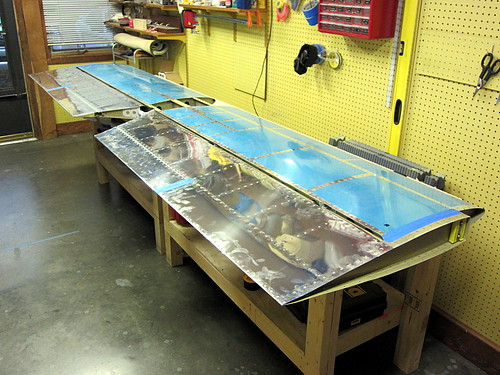
With the tail cone mostly done, it was time to get started on attaching all of the subassemblies I had built to date together. The first step was to secure the horizontal stabilizer to the work benches with some woodscrews. From there, each of the elevators was attached to the horizontal stabilizers one at a time.
This was a tedious process because getting those two AN3 bolts through the rod-end bearings is a bit tricky and requires two people (at least in my setup). Once the two bolts are in place, you measure the clearance between the counterweight arm and the side of the horizontal stabilizer... then take the whole thing off again to make an adjustment to the rod-end bearing. Rinse, repeat. Then do the other elevator. Bit of a pain, but it when it was done, the results looked great!
Drilling the hole in the control horns for the central bearing was straightforward, and the AN4 bolt that connects both sides went through without a hitch. However, I have no idea how I'm going to thread washers into the gaps between the bearing and the horns. I suspect I need a new tool or something for that. I'm going to have to ask some of my builder friends what to do here.
Unfortunately I'm leaving town in a day or so for three weeks. So there will be another work-related RV-10 hiatus. :(
14 Aug 2010
It's been awhile; I've been out of town for work, but I'm back now and spent a quick hour today getting some tasks ready for the main event of the empennage attach chapter. Namely, the day I'll fully attach the entire tail section of the aircraft in my driveway.
While I was gone, I looked through the plans and made a list of small tasks that needed to be taken care of before I could do the actual attachment, and set about doing some of those things today. First off, the elevator trim bracket was a bit long on the aft edge for the holes in the aft deck to line up with the nutplates in the bracket now that I've bolted and riveted the aft end of the tailcone together. It was only long by about 1/16", so I just took the scotchbrite wheel to that edge and now it fits like a champ.
Next, I checked my hardware bins and made sure I had the necessary bolts and washers for the actual attachment. No problems there.
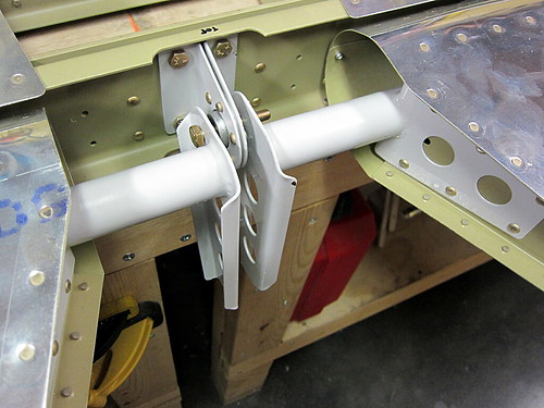
Finally, I addressed the problem I had earlier with the elevator trim bellcrank mechanism binding rather than rotating freely. I measured the gap as-built and the thickness of the bellcrank plate plus the two washers was too large by 0.02". Not much, but enough to make it too tight. The suggested fix from the forums was to grind down the washers using a belt sander (which I don't have). Instead, I just took the scotchbrite wheel to the sides of the bellcrank plate and took off the primer and a bit of the metal. It did this slowly and in many iterations to ensure that I wasn't taking off too much. Each time, I'd load the parts back up and rotate it a few times and the washers would leave marks where the plate was still too thick. Once I got the right amount off, it spins freely. The change in thickness is not visually perceptible, so I'm not concerned about compromosing the structural integrity of the plate. Here's a picture of the bellcrank mechanism from the bottom after everything was fully assembled.
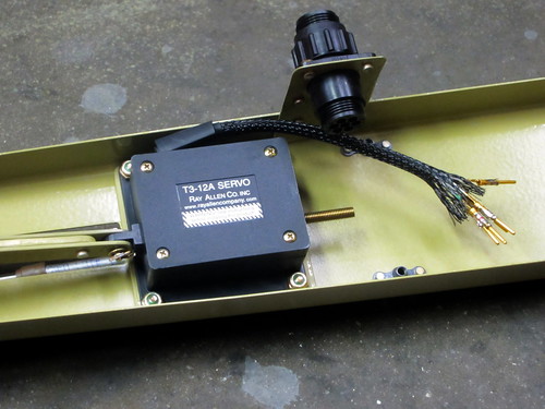
Of course, this also means that I finally installed the T3-12A servo in its spot just aft of the bellcrank. I haven't connected the wires to the CPC on the drop plate yet because I want to put a strain relief cap on it but I don't have one in stock. Time for a mouser.com order.
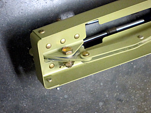
And here's the final view of the forward end of the trim push-pull cables installed onto the bellcrank.
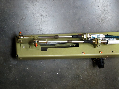
It was really hard getting the right-side cable through the mounting bracket; for some reason that hole seems to be just a fraction smaller than the other. But I did manage to get it through and they look great. I'm thinking I should take off those labels that read "Not for use in aircraft" in bright red letters... (a note to those who are concerned by this, it's a liability thing... the cables are perfectly acceptable for use in aircraft and are actually supplied by the kit manufacturer).
The bellcrank is shown in the full nose-down trim position here, with the cables fully extended on this end.
16 Aug 2010
I did a couple more mini-tasks getting ready for the big empennage attach day in the ill-defined future, namely making the elevator bellcrank angle template out of some foam board and getting the forward end of the elevator trim push-pull cables tightened down at the right length. The only remaining tasks here are to make the 2x4 block for squaring the horizontal stabilier and to put the rod-end bearings into the rudder. One those are done, I'll be on hold with empennage attach until I have a full day with a helper that I can spend doing the rest of the chapter. It's possible this will occur this coming Sunday, or perhaps it's weeks away. So I moved on to starting the empennage fairings chapter in the meantime.
18 Aug 2010
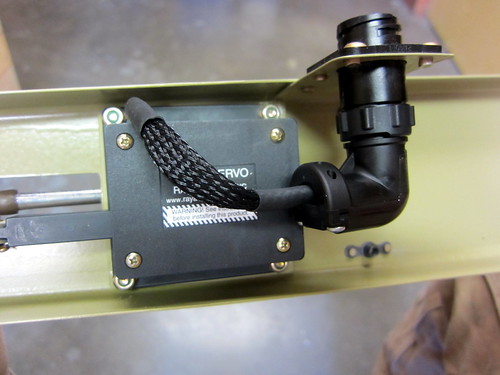
Finally got the strain relief parts in for my circular plastic connectors. I went ahead and put a right-angle one on the elevator trim servo, finishing off this assembly.
22 Aug 2010
Today was the big empennage attach day! I started in the morning with Nina's help, getting the tail cone moved out into the driveway and the horizontal stabilizer placed on top of it.
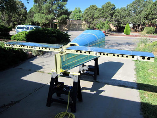
It took quite a few iterations to get the distances from the HS tips to the centerline of the tailcone to be even on both sides, but we finally managed to get it square and the bolt holes were match drilled, deburred, and bolted down. Sitting on my saw horses, the tailcone + horizontal stabilizer combo was balanced well, but it didn't take much for it to want to roll. I'm glad it wasn't windy. At some point during this part of the show, Bob showed up to lend a hand. Having a second person for this section of the plans is pretty much mandatory, and I would recommend three for many portions.
Next up was the vertical stabilizer, which also went on without a hitch. Some of the lower bolts were a pain to get tightened down since one arm had to be jammed all the way into the small access panels at the rear of the tail cone.
The elevators came next, and would have been a pain with just two people. Luckily, Jeff and Skip arrived from the local EAA chapter to see what was going on and lent a hand for the remainder of the day's activities.
Jeremy, Bob, and I had already worked out the appropriate rod-end bearing distance for the elevators to not come in contact with the horizontal stabilizer, but when we mounted them again today, there was definitely some contact. We tried adjusting the rod-end bearing displacements, but this made the center hinge hole not line up correctly. I definitely didn't want binding in this joint, so I reset the rod-end bearings to their original positions and just shaved down the inboard edge of the elevator counterweight tips until the correct spacing was achieved. In the end it wasn't a big deal; very little material needed to be removed. A mill file and the mini-scotchbright wheel attachment for my die grinder did the trick. A set of temporary assembly pins from Avery Tools also proved invaluable here.
I tested the desired deflection angles for the elevators, got exactly the right angle for the nose-down setting, but was two degrees short on the nose-up setting. So I used the scotch bright grinder again and took a very small amount of material off of the nose-up elevator stop bar. Now the angles are perfect.
With both elevators in place, the pushrod came out of storage and was attached at both ends. With the aft rod-end bearing in place and threaded half-way into the threaded insert, the forward rod-end bearing had to be fully threaded into the insert in order to make the desired angle on the bellcrank. This is fine, I'll probably average it out by backing out some fixed number of turns from the forward bearing and going inwards by the same number on the aft one.

Then, it was time for the final piece. I was worried about the rudder attachment because, with its three hinges, it could be a real bear to get it aligned. Much to my surprise, however, it went in perfectly the first time with Van's recommended distances for the three rod-end bearings. The gap between the counterweight and the vertical stabilizer was also perfect and straight. Cool!
I decided to skip the elevator trim mechanism install for now; I didn't relish the idea of threading through those cables, just to un-do it later. I'll save that for final assembly. Other than the tip fairings for the horizontal and vertical stabilizers, the empennage kit plans are complete! Non-plans tasks remaining include rudder trim and blending the fairings, but that's it!
When we had the assembly complete, we could see that a rain storm was moving in so we made a mad dash to get everything disassmbled and stored in the house. We didn't quite finish in time. I'm sorry there aren't more pictures of the fully-assembled tail.
Had to spend some time mopping up all the water from the horizontal stabilizer and tail cone, but no harm was done.
Time invested on this task: 19 hours (10 by me)
23 Jul 2010
With the tail cone mostly done, it was time to get started on attaching all of the subassemblies I had built to date together. The first step was to secure the horizontal stabilizer to the work benches with some woodscrews. From there, each of the elevators was attached to the horizontal stabilizers one at a time.
This was a tedious process because getting those two AN3 bolts through the rod-end bearings is a bit tricky and requires two people (at least in my setup). Once the two bolts are in place, you measure the clearance between the counterweight arm and the side of the horizontal stabilizer... then take the whole thing off again to make an adjustment to the rod-end bearing. Rinse, repeat. Then do the other elevator. Bit of a pain, but it when it was done, the results looked great!
Drilling the hole in the control horns for the central bearing was straightforward, and the AN4 bolt that connects both sides went through without a hitch. However, I have no idea how I'm going to thread washers into the gaps between the bearing and the horns. I suspect I need a new tool or something for that. I'm going to have to ask some of my builder friends what to do here.
Unfortunately I'm leaving town in a day or so for three weeks. So there will be another work-related RV-10 hiatus. :(
14 Aug 2010
It's been awhile; I've been out of town for work, but I'm back now and spent a quick hour today getting some tasks ready for the main event of the empennage attach chapter. Namely, the day I'll fully attach the entire tail section of the aircraft in my driveway.
While I was gone, I looked through the plans and made a list of small tasks that needed to be taken care of before I could do the actual attachment, and set about doing some of those things today. First off, the elevator trim bracket was a bit long on the aft edge for the holes in the aft deck to line up with the nutplates in the bracket now that I've bolted and riveted the aft end of the tailcone together. It was only long by about 1/16", so I just took the scotchbrite wheel to that edge and now it fits like a champ.
Next, I checked my hardware bins and made sure I had the necessary bolts and washers for the actual attachment. No problems there.
Finally, I addressed the problem I had earlier with the elevator trim bellcrank mechanism binding rather than rotating freely. I measured the gap as-built and the thickness of the bellcrank plate plus the two washers was too large by 0.02". Not much, but enough to make it too tight. The suggested fix from the forums was to grind down the washers using a belt sander (which I don't have). Instead, I just took the scotchbrite wheel to the sides of the bellcrank plate and took off the primer and a bit of the metal. It did this slowly and in many iterations to ensure that I wasn't taking off too much. Each time, I'd load the parts back up and rotate it a few times and the washers would leave marks where the plate was still too thick. Once I got the right amount off, it spins freely. The change in thickness is not visually perceptible, so I'm not concerned about compromosing the structural integrity of the plate. Here's a picture of the bellcrank mechanism from the bottom after everything was fully assembled.
Of course, this also means that I finally installed the T3-12A servo in its spot just aft of the bellcrank. I haven't connected the wires to the CPC on the drop plate yet because I want to put a strain relief cap on it but I don't have one in stock. Time for a mouser.com order.
And here's the final view of the forward end of the trim push-pull cables installed onto the bellcrank.
It was really hard getting the right-side cable through the mounting bracket; for some reason that hole seems to be just a fraction smaller than the other. But I did manage to get it through and they look great. I'm thinking I should take off those labels that read "Not for use in aircraft" in bright red letters... (a note to those who are concerned by this, it's a liability thing... the cables are perfectly acceptable for use in aircraft and are actually supplied by the kit manufacturer).
The bellcrank is shown in the full nose-down trim position here, with the cables fully extended on this end.
16 Aug 2010
I did a couple more mini-tasks getting ready for the big empennage attach day in the ill-defined future, namely making the elevator bellcrank angle template out of some foam board and getting the forward end of the elevator trim push-pull cables tightened down at the right length. The only remaining tasks here are to make the 2x4 block for squaring the horizontal stabilier and to put the rod-end bearings into the rudder. One those are done, I'll be on hold with empennage attach until I have a full day with a helper that I can spend doing the rest of the chapter. It's possible this will occur this coming Sunday, or perhaps it's weeks away. So I moved on to starting the empennage fairings chapter in the meantime.
18 Aug 2010
Finally got the strain relief parts in for my circular plastic connectors. I went ahead and put a right-angle one on the elevator trim servo, finishing off this assembly.
22 Aug 2010
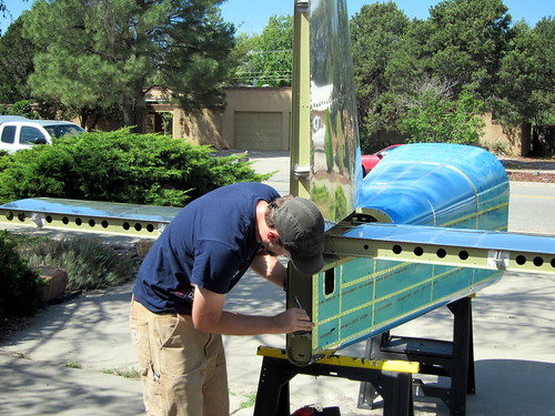
Today was the big empennage attach day! I started in the morning with Nina's help, getting the tail cone moved out into the driveway and the horizontal stabilizer placed on top of it.
It took quite a few iterations to get the distances from the HS tips to the centerline of the tailcone to be even on both sides, but we finally managed to get it square and the bolt holes were match drilled, deburred, and bolted down. Sitting on my saw horses, the tailcone + horizontal stabilizer combo was balanced well, but it didn't take much for it to want to roll. I'm glad it wasn't windy. At some point during this part of the show, Bob showed up to lend a hand. Having a second person for this section of the plans is pretty much mandatory, and I would recommend three for many portions.
Next up was the vertical stabilizer, which also went on without a hitch. Some of the lower bolts were a pain to get tightened down since one arm had to be jammed all the way into the small access panels at the rear of the tail cone.
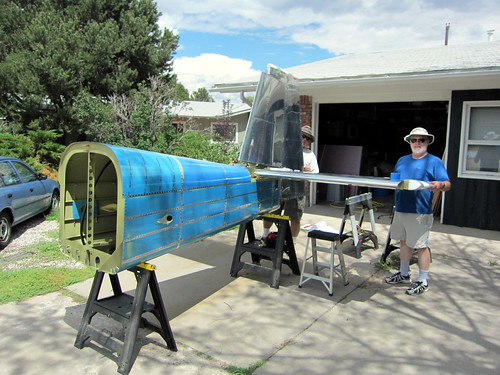
The elevators came next, and would have been a pain with just two people. Luckily, Jeff and Skip arrived from the local EAA chapter to see what was going on and lent a hand for the remainder of the day's activities.
Jeremy, Bob, and I had already worked out the appropriate rod-end bearing distance for the elevators to not come in contact with the horizontal stabilizer, but when we mounted them again today, there was definitely some contact. We tried adjusting the rod-end bearing displacements, but this made the center hinge hole not line up correctly. I definitely didn't want binding in this joint, so I reset the rod-end bearings to their original positions and just shaved down the inboard edge of the elevator counterweight tips until the correct spacing was achieved. In the end it wasn't a big deal; very little material needed to be removed. A mill file and the mini-scotchbright wheel attachment for my die grinder did the trick. A set of temporary assembly pins from Avery Tools also proved invaluable here.
I tested the desired deflection angles for the elevators, got exactly the right angle for the nose-down setting, but was two degrees short on the nose-up setting. So I used the scotch bright grinder again and took a very small amount of material off of the nose-up elevator stop bar. Now the angles are perfect.
With both elevators in place, the pushrod came out of storage and was attached at both ends. With the aft rod-end bearing in place and threaded half-way into the threaded insert, the forward rod-end bearing had to be fully threaded into the insert in order to make the desired angle on the bellcrank. This is fine, I'll probably average it out by backing out some fixed number of turns from the forward bearing and going inwards by the same number on the aft one.
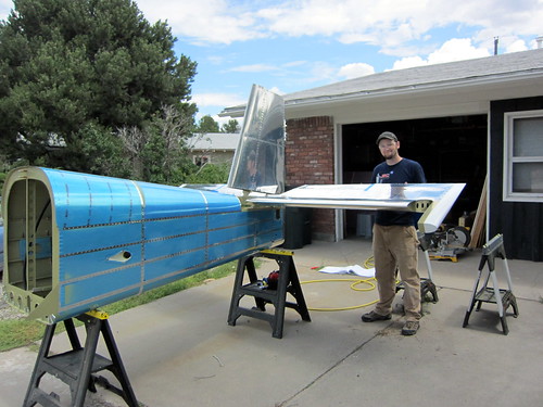
Then, it was time for the final piece. I was worried about the rudder attachment because, with its three hinges, it could be a real bear to get it aligned. Much to my surprise, however, it went in perfectly the first time with Van's recommended distances for the three rod-end bearings. The gap between the counterweight and the vertical stabilizer was also perfect and straight. Cool!
I decided to skip the elevator trim mechanism install for now; I didn't relish the idea of threading through those cables, just to un-do it later. I'll save that for final assembly. Other than the tip fairings for the horizontal and vertical stabilizers, the empennage kit plans are complete! Non-plans tasks remaining include rudder trim and blending the fairings, but that's it!
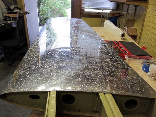
When we had the assembly complete, we could see that a rain storm was moving in so we made a mad dash to get everything disassmbled and stored in the house. We didn't quite finish in time. I'm sorry there aren't more pictures of the fully-assembled tail.
Had to spend some time mopping up all the water from the horizontal stabilizer and tail cone, but no harm was done.