| Workshop | Empennage | Wings | Fuselage | Contact |
| <-- September 2011 | November 2011 --> |
Chronological Updates, October, 2011
8 Oct 2011
Today is the second anniversary of the arrival of my empennage kit! Two years in and I'm about half-way done with the wings. Like I've said before, this is not a speed-build.
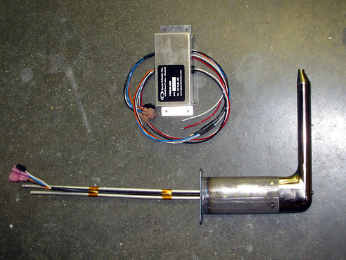
Today was all about the pitot tube. My Dynon heated pitot/AoA probe arrived in the mail last week, along with the matching Gretz mount kit (and my Bob Archer NAV antenna and some more Akzo).
I had been spending a lot of time recently deburring the outer face of the skins of the left wing, and yesterday I finally got to the point where the outboard bottom skin was ready to come off. With the skin off, I had access to the areas I needed to begin fabricating the pitot doubler and its accessories.
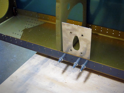
The doubler that comes with the Gretz mount has a joggled end piece that goes on the inside of the aft row of rivet holes in the main spar flange. The only questions is where along the spar to place the pitot tube. Gretz recommends putting it adjacent to a bay with an access panel and outboard of the aileron actuation hardware. However, they also caution against putting it near the tie-down lest the probe interfere with the rope. I decided to go with the same position Tim Olson did, which was the second bay inboard from the wing tip, up against the outboard-side rib (see above).
With the location selected, I centered the doubler on four holes of the spar flange and match-drilled them. If I had put the doubler up against the rib, only three of the holes would have lined up with the doubler. I decided that having a fourth hole and a longer angle bracket connecting to the rib was better than three holes and a shorter angle bracket. Fabricating the angle bracket was easy, I just bent a piece of 0.032" alclad plate and match drilled it to the rib with four holes.
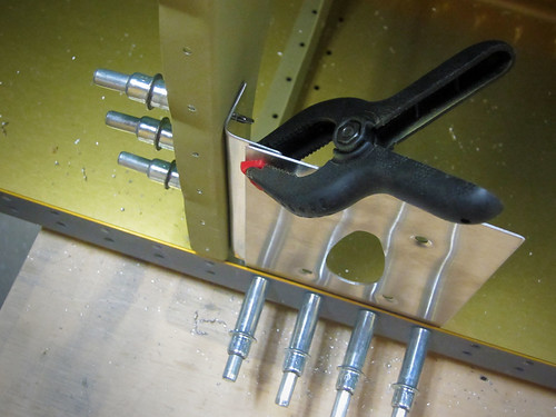
I did not drill out any more of the holes in the doubler, including the ones shared with the angle bracket, because I wanted to drill these from the inside so I could tell easily that the holes would be well-aligned on the parts. However, to do this, I'd need to have the top skin off the wing and have the bottom skin back on the wing. I'm glad I did this before riveting the top skin; I'd recommend the same to any other builder. Anyway, I went ahead and finished all the outer-surface deburring on the outboard top skin and removed it, then cleco'd the outboard bottom skin back in place. After sliding the pitot doubler inbetween the angle bracket and the skin, and clecoing the forward row of holes, I was able to centerpunch and drill a series of 10 additional rivet holes connecting the doubler, angle bracket, and bottom skin.
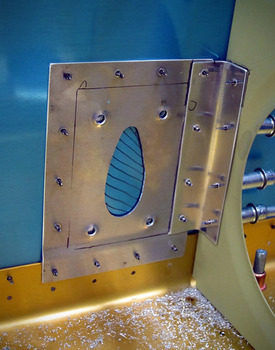
I also match drilled the four screw holes for attachment of the pitot mount and marked the teardrop area of the skin for removal. I put a few big holes in the teardrop using a unibit, then took the skin back off (again) and opened up the rest of the hole with a nibbler and some files. After a few test fits, the teardrop hole was perfect and I put the skin back on (again) for a full fit test fo the pitot system.
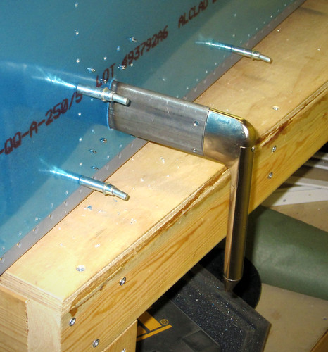
Nothing too exciting to report about the outside, other than it fits well and looks good.
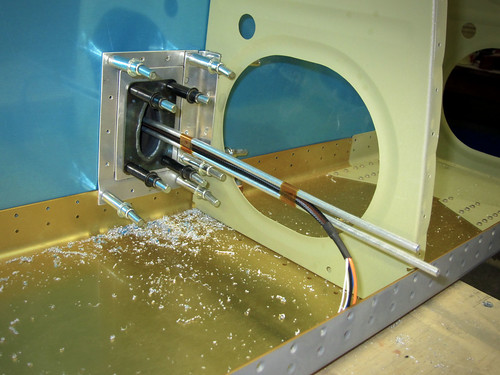
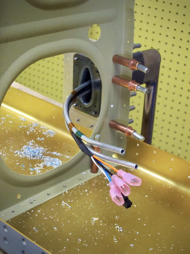
The inside view shows the two pressure tubes coming up through the mount as well as the heater control wires. I'm going to mount the heater control box on the outboard face of the outboard wing rib so that it is directly accessible from the wingtip. The wires are sufficiently long already, and can be secured to the outer surface of the conduit if need be. I'll bend the pressure tubes outboard as well, so that the aluminum tube to plastic tube adapters can be easily reached from the wingtip. Forming the tubes so that they can be inserted through the straight mount pipe but still curve through the lightening hole in the rib is the next problem to be solved.
10 Oct 2011
Did a bit more work on the pitot tube assembly this weekend; got the tubing and wire run coming up out of the pitot tube bent over and through the adjacent lightening hole.
Also, I finished deburring the outer surface holes of all left wing skins. I started disassembling the left wing and prepping the smaller parts as I separated them. The aft spar doubler plates are ready for chemistry, as are the wing walk doublers and all of the pieces associated with the pitot tube. I did a bunch of hole deburring, but there is still quite a bit left (lots of holes in the wings!!). As I'm taking individual ribs off of the main spar, I'm deburring the flanges and dimpling where appropriate, and expanding the forward tooling hole for use by the pitot plumbing line. I'll need to figure out where I'm going to mount my APRS equipment (probably the left wingtip) and run some wire holes for that antenna as well (the APRS antenna will be located one bay inboard of the pitot tube). Here's a list for my own bookkeeping of tasks remaining on the left wing before it will essentially be ready for the next chemistry pass, at which point I'll shelve it and start on the right wing.
Today is the second anniversary of the arrival of my empennage kit! Two years in and I'm about half-way done with the wings. Like I've said before, this is not a speed-build.
Today was all about the pitot tube. My Dynon heated pitot/AoA probe arrived in the mail last week, along with the matching Gretz mount kit (and my Bob Archer NAV antenna and some more Akzo).
I had been spending a lot of time recently deburring the outer face of the skins of the left wing, and yesterday I finally got to the point where the outboard bottom skin was ready to come off. With the skin off, I had access to the areas I needed to begin fabricating the pitot doubler and its accessories.
The doubler that comes with the Gretz mount has a joggled end piece that goes on the inside of the aft row of rivet holes in the main spar flange. The only questions is where along the spar to place the pitot tube. Gretz recommends putting it adjacent to a bay with an access panel and outboard of the aileron actuation hardware. However, they also caution against putting it near the tie-down lest the probe interfere with the rope. I decided to go with the same position Tim Olson did, which was the second bay inboard from the wing tip, up against the outboard-side rib (see above).
With the location selected, I centered the doubler on four holes of the spar flange and match-drilled them. If I had put the doubler up against the rib, only three of the holes would have lined up with the doubler. I decided that having a fourth hole and a longer angle bracket connecting to the rib was better than three holes and a shorter angle bracket. Fabricating the angle bracket was easy, I just bent a piece of 0.032" alclad plate and match drilled it to the rib with four holes.
I did not drill out any more of the holes in the doubler, including the ones shared with the angle bracket, because I wanted to drill these from the inside so I could tell easily that the holes would be well-aligned on the parts. However, to do this, I'd need to have the top skin off the wing and have the bottom skin back on the wing. I'm glad I did this before riveting the top skin; I'd recommend the same to any other builder. Anyway, I went ahead and finished all the outer-surface deburring on the outboard top skin and removed it, then cleco'd the outboard bottom skin back in place. After sliding the pitot doubler inbetween the angle bracket and the skin, and clecoing the forward row of holes, I was able to centerpunch and drill a series of 10 additional rivet holes connecting the doubler, angle bracket, and bottom skin.
I also match drilled the four screw holes for attachment of the pitot mount and marked the teardrop area of the skin for removal. I put a few big holes in the teardrop using a unibit, then took the skin back off (again) and opened up the rest of the hole with a nibbler and some files. After a few test fits, the teardrop hole was perfect and I put the skin back on (again) for a full fit test fo the pitot system.
Nothing too exciting to report about the outside, other than it fits well and looks good.
The inside view shows the two pressure tubes coming up through the mount as well as the heater control wires. I'm going to mount the heater control box on the outboard face of the outboard wing rib so that it is directly accessible from the wingtip. The wires are sufficiently long already, and can be secured to the outer surface of the conduit if need be. I'll bend the pressure tubes outboard as well, so that the aluminum tube to plastic tube adapters can be easily reached from the wingtip. Forming the tubes so that they can be inserted through the straight mount pipe but still curve through the lightening hole in the rib is the next problem to be solved.
10 Oct 2011
Did a bit more work on the pitot tube assembly this weekend; got the tubing and wire run coming up out of the pitot tube bent over and through the adjacent lightening hole.
Also, I finished deburring the outer surface holes of all left wing skins. I started disassembling the left wing and prepping the smaller parts as I separated them. The aft spar doubler plates are ready for chemistry, as are the wing walk doublers and all of the pieces associated with the pitot tube. I did a bunch of hole deburring, but there is still quite a bit left (lots of holes in the wings!!). As I'm taking individual ribs off of the main spar, I'm deburring the flanges and dimpling where appropriate, and expanding the forward tooling hole for use by the pitot plumbing line. I'll need to figure out where I'm going to mount my APRS equipment (probably the left wingtip) and run some wire holes for that antenna as well (the APRS antenna will be located one bay inboard of the pitot tube). Here's a list for my own bookkeeping of tasks remaining on the left wing before it will essentially be ready for the next chemistry pass, at which point I'll shelve it and start on the right wing.
- finish deburring and dimpling rib flanges
- expand rib tooling holes for pitot plumbing
- make final decision wrt where the AoA line will run
- make rib holes for APRS antenna line
- debur/dimple rear spar
- debur inner surface skin holes
- debur skin edges
- debur J-stiffener edges
- remove vinyl stripes from skin
- taper skin lap joint
- scuff inner skin surfaces
- dimple skin
| <-- September 2011 | November 2011 --> |