
| Workshop | Empennage | Wings | Fuselage | Contact |
| <-- January 2011 | March 2011 --> |
Chronological Updates, February, 2011
7 Feb 2011
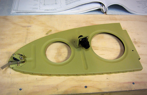
I've been on travel for the last week, but before that I did some work while waiting for a rivet helper. Specifically, I set the fully-assembled right leading edge aside and put together the left leading edge. The left side is more complicated than the right because it includes the stall warning switch, access hatch, and wiring connector. I started by attaching the previously-constructed stall warning assembly and the wiring connector to the inboard rib:
I assembled the leading edge to see how the stall warning vane adjustment was. It was actually really easy to rotate into a position where it performed as described in the plans. The switch engages after about 1mm of travel and the vane sits perpendicular to the skin tangent when at rest. Perfect. No bending of the vane or the switch arm was required.
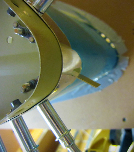
I went ahead and riveted in the access hatch doubler so that I could get a sense of how difficult it would be to install the stall warning switch after the wing was assembled.
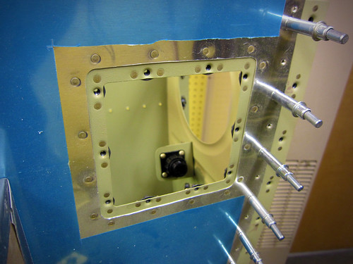
It turns out that it will be really difficult to install or adjust the stall warning switch through the access hatch; my forearm fills most of the open space, so I won't be able to see anything while I'm working on it. Furthermore, the location of the screws makes using a screwdriver problematic due to the proximiy of the skin. Anyway, I decided to just torque-seal the bolts and screws and leave it installed. Hopefully it won't get bumped or bent or something between now and when the plane flies because I am really not looking forward to adjusting anything here. Inspection will be straightforward; I'll just stick my little camera in there and take a picture showing the orange torque seal intact and call it done.
Here's a shot of the access hatch with the cover in place. It fits flush, but only with a bit of adjustment. I had to put in a bunch of the screws, then get the hatch cover aligned properly, then tighten the screws. Good enough in my book...
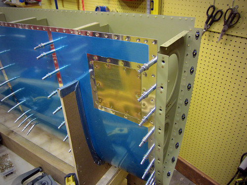
Finally, here is a view looking forward inside the inboard bay of the left leading edge assembly.
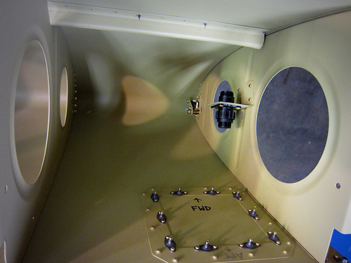
It still needs wires, and since this picture was taken some wiring work has been done. I cut the 100" lengths of 18AWG wire for the stall switch, which I determined may be a bit limiting depending on where I want to put the wing root CPC... Of course this determination was made after I made the 100" cuts and crimped on the supplied quick connects, because I'm an idiot sometimes.
I replaced the empty plug you see above with a connector cap, since the plug (and whatever accessory it is attached to) is deferred to post-flight at this point. I bought a bunch of wing wire from Stein which will allow me to wire up the connector seen here to the wing root, but I neglected to order the required CPC pins/sockets from Mouser with my most recent order, so I can't actually populate the connector yet. Eventually, the plan is to wire it up with a shielded twisted pair to possibly convey an analog video signal from a camera, then six 22awg wires for general purpose signals. This should cover any accessory I eventually mount here (except perhaps an antenna that would require some coax... but I've got plenty of room for those elsewhere in the wing).
13 Feb 2011
Still waiting on riveting help to finish up the leading edges. In lieu of that, I started on the flaps chapter.
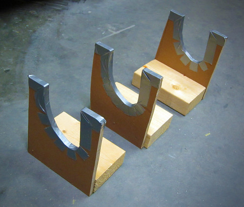
First thing to do was to cut out a set of flap cradles. The plans call for six and recommend building both flaps at the same time. I'm just going to do one set and build the flaps serially (at least for now) and see how that goes.
With those out of the way, I located all of the parts for the front section of the left flap, matched drilled the holes they share, and deburred all edges and holes.
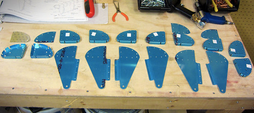
These parts will become all of the nose ribs as well as the three hinge hanger assemblies. I stopped here for the night.
14 Feb 2011
Did a quick hour of work on the left flap this evening. The initial assembly goes pleasingly fast; in no time at all I had a fully assembled flap sitting on my workbench.
I started with the internals, assembling the various ribs and hinge pieces onto the flap spar:
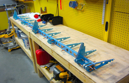
Next up came the four skin pieces. The top and bottom pieces were a piece of cake; the leading edges required a bit of persuading, but were much easier than their aileron equivalents.
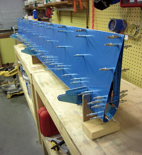
The next step is to drill all the skin holes, which is going to take awhile, so I called it quits here for the evening.
16 Feb 2011
Did all of the match-drilling of the skins for the left flap today. Not much visually interesting there. Also match-drilled the hinge hanger halves together. This required a bit more work than usual because the two flange halves weren't seating against each other all that well. They weren't even parallel. So I clamped them together before drilling.
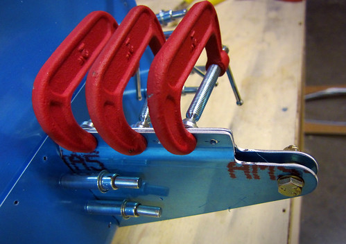
I just hope that the double-flush rivets that go in these holes will not be compromised by the bending force of the flanges trying to not be flat up against one another. Shouldn't be a problem.
Once this was done, I disassembled the entire left flap, being careful to mark all parts for position and orientation where necessary. I started to deburr a few of the smaller parts, but my cordless screwdriver ran out of batteries almost immediately and I didn't feel like doing it the hard way. So that was it for the night.
22 Feb 2011
Got Bob to come by tonight and we ripped through all the rivets in the left leading edge assembly.
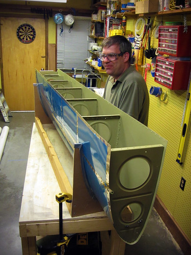
Somewhere along the second to last row of rivets was the 6000th rivet in the airplane! This assembly is now complete per the plans, but I still have to do the landing light lens and lens holders.
I've been on travel for the last week, but before that I did some work while waiting for a rivet helper. Specifically, I set the fully-assembled right leading edge aside and put together the left leading edge. The left side is more complicated than the right because it includes the stall warning switch, access hatch, and wiring connector. I started by attaching the previously-constructed stall warning assembly and the wiring connector to the inboard rib:

I assembled the leading edge to see how the stall warning vane adjustment was. It was actually really easy to rotate into a position where it performed as described in the plans. The switch engages after about 1mm of travel and the vane sits perpendicular to the skin tangent when at rest. Perfect. No bending of the vane or the switch arm was required.

I went ahead and riveted in the access hatch doubler so that I could get a sense of how difficult it would be to install the stall warning switch after the wing was assembled.

It turns out that it will be really difficult to install or adjust the stall warning switch through the access hatch; my forearm fills most of the open space, so I won't be able to see anything while I'm working on it. Furthermore, the location of the screws makes using a screwdriver problematic due to the proximiy of the skin. Anyway, I decided to just torque-seal the bolts and screws and leave it installed. Hopefully it won't get bumped or bent or something between now and when the plane flies because I am really not looking forward to adjusting anything here. Inspection will be straightforward; I'll just stick my little camera in there and take a picture showing the orange torque seal intact and call it done.
Here's a shot of the access hatch with the cover in place. It fits flush, but only with a bit of adjustment. I had to put in a bunch of the screws, then get the hatch cover aligned properly, then tighten the screws. Good enough in my book...

Finally, here is a view looking forward inside the inboard bay of the left leading edge assembly.

It still needs wires, and since this picture was taken some wiring work has been done. I cut the 100" lengths of 18AWG wire for the stall switch, which I determined may be a bit limiting depending on where I want to put the wing root CPC... Of course this determination was made after I made the 100" cuts and crimped on the supplied quick connects, because I'm an idiot sometimes.
I replaced the empty plug you see above with a connector cap, since the plug (and whatever accessory it is attached to) is deferred to post-flight at this point. I bought a bunch of wing wire from Stein which will allow me to wire up the connector seen here to the wing root, but I neglected to order the required CPC pins/sockets from Mouser with my most recent order, so I can't actually populate the connector yet. Eventually, the plan is to wire it up with a shielded twisted pair to possibly convey an analog video signal from a camera, then six 22awg wires for general purpose signals. This should cover any accessory I eventually mount here (except perhaps an antenna that would require some coax... but I've got plenty of room for those elsewhere in the wing).
13 Feb 2011
Still waiting on riveting help to finish up the leading edges. In lieu of that, I started on the flaps chapter.
First thing to do was to cut out a set of flap cradles. The plans call for six and recommend building both flaps at the same time. I'm just going to do one set and build the flaps serially (at least for now) and see how that goes.

With those out of the way, I located all of the parts for the front section of the left flap, matched drilled the holes they share, and deburred all edges and holes.

These parts will become all of the nose ribs as well as the three hinge hanger assemblies. I stopped here for the night.
14 Feb 2011
Did a quick hour of work on the left flap this evening. The initial assembly goes pleasingly fast; in no time at all I had a fully assembled flap sitting on my workbench.
I started with the internals, assembling the various ribs and hinge pieces onto the flap spar:

Next up came the four skin pieces. The top and bottom pieces were a piece of cake; the leading edges required a bit of persuading, but were much easier than their aileron equivalents.

The next step is to drill all the skin holes, which is going to take awhile, so I called it quits here for the evening.
16 Feb 2011
Did all of the match-drilling of the skins for the left flap today. Not much visually interesting there. Also match-drilled the hinge hanger halves together. This required a bit more work than usual because the two flange halves weren't seating against each other all that well. They weren't even parallel. So I clamped them together before drilling.

I just hope that the double-flush rivets that go in these holes will not be compromised by the bending force of the flanges trying to not be flat up against one another. Shouldn't be a problem.
Once this was done, I disassembled the entire left flap, being careful to mark all parts for position and orientation where necessary. I started to deburr a few of the smaller parts, but my cordless screwdriver ran out of batteries almost immediately and I didn't feel like doing it the hard way. So that was it for the night.
22 Feb 2011
Got Bob to come by tonight and we ripped through all the rivets in the left leading edge assembly.

Somewhere along the second to last row of rivets was the 6000th rivet in the airplane! This assembly is now complete per the plans, but I still have to do the landing light lens and lens holders.
| <-- January 2011 | March 2011 --> |