| Workshop | Empennage | Wings | Fuselage | Contact |
| <-- November 2009 | January 2010 --> |
Chronological Updates, December 2009
2 Dec 2009
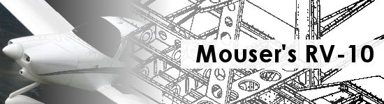
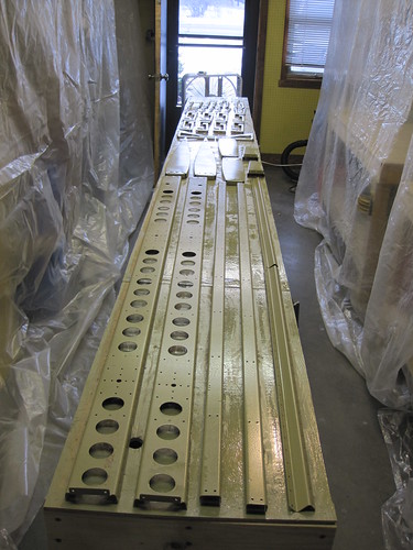
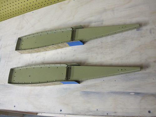
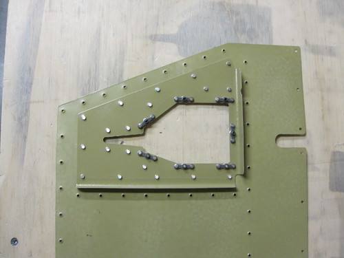
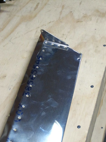
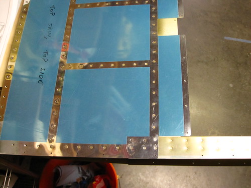
Two days ago, Bob came over and we did a marathon session of match drilling. In about three hours, we knocked out all of the holes in all four skins. It was epic and tedious. And while I'm glad to be through with the match drilling phase of elevator operations, that leaves me unfortunately at the deburring stage which I like even less. Neither of these tasks accomplish much that is photo worthy. Here is a shot of one of the elevators with every skin hole cleco'd:
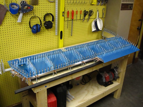
Last night, while everything was still assembled, I figured out where I wanted to mount the elevator static wicks and worked out the mounting hardware. As with the rudder, the wicks will attach via anchor nuts with elastic inserts. I'll mount the wicks to the bottom skins so that, if I choose to remove them, the mount holes won't be visible. Each elevator gets two wicks, one in line with the outer-most rivet line and one 12 inches inboard from that. The forward anchor nut for the outboard wick is attached thusly:
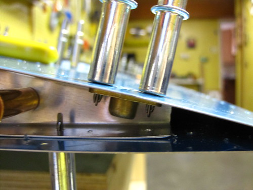
The aft anchor nut for the outboard wick is off the end of the flage for the tip piece, so it needs a doubler. For clearance reasons with the trailing edge extrusion, I used a one-lug anchor nut and mounted it perpendicular to the foreward anchor nut. I fabricated this small doubler out of a piece of scrap and used it as a template to drill the holes for the aft anchor nut:
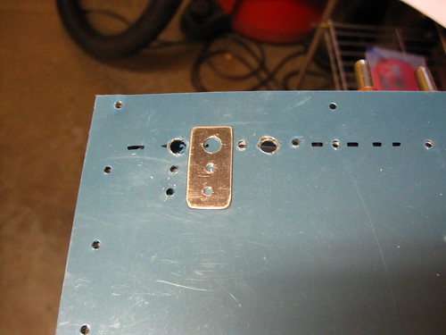
The inboard wick has no underlying support rib to take advantage of, so I made a larger doubler that covered both anchor nuts as was able to include a couple of rivet holes just to add support for the doubler.
This doubler was used as a template for the inboard wick mounting holes, which are situated 12 inches inboard of the outboard holes, as per the Dayton Granger recommendations for the RV-10.
With all of the static wick holes drilled, I was done with the first assembly stage of the elevators and called it an evening for last night. Today I disassembled both elevators entirely and started in on the exceedingly dull task of deburring every hole. I managed to get all of the non-skin parts done before being overcome with ennui and calling it a night. Still need to deburr the skins, then it's time to start dimpling!
12 Dec 2009
In the past 10 days, I've procrastinated a lot because the spectre of deburring the skin holes was looming over me and I just didn't want to do it. Every now and then I'd pull one of the four skins out and do one side, but otherwise it became an exercise in seeing how many other tasks on the elevators I could get ahead on without having to have the skins deburred first.
The most significant of these get-ahead tasks was to work on the trim tabs. I intended to do these ahead of schedule anyway since I wanted to prime the parts at the same time that I primed the rest of the elevator bits. So the skin deburring procrastination just gave me another excuse to get on this. With only four parts per tab, they go pretty quickly.
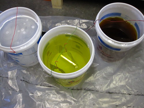
I also got ahead on the alodining process, doing the smaller parts by just dunking them in the storage buckets that I keep the chemicals in. I strung some 18awg solid-core wire across the top and then hung the parts into the liquid from that. It worked great and I was able to drastically reduce the number of parts that needed the huge dunk tank. I didn't want to get the dunk tank out until I was ready to prime, because it's a pain to move and the back of it will be the priming surface.
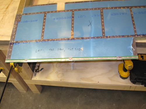
And with that, I really had nothing left to do but finish the skins, so I sucked it up and got it over with. I was so happy to have finished the deburring that a whirlwind of activity ensued as soon as the last hole was deburred. All of the rivet lines had their vinyl removed on the outer surface, and the inner surface vinyls were entirely removed. All of the holes except the leading edge holes were dimpled. The inner surfaces were scuffed and then cleaned with acetone (note to self: next time scuff and clean BEFORE dimpling; the dimples tear up the scotchbrite pads).
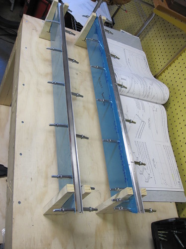
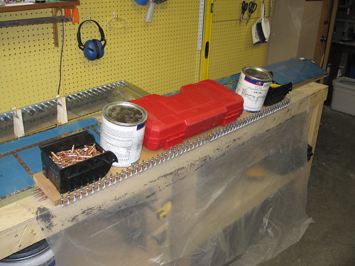
The dunk tank was set up as before, and the length set to a few inches longer than the forward elevator spar. I lined it with 4 mil plastic sheet again and added the alumiprep and distilled water. I recycled the distilled water from last time even though it was quite yellow from alodine. When all of the parts had been etched with the alumiprep, I emptied that trough and replaced it with alodine. The same process was repeated with the alodine and then all of the parts were hung up to dry.
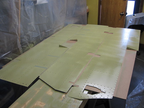
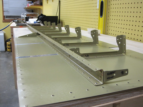
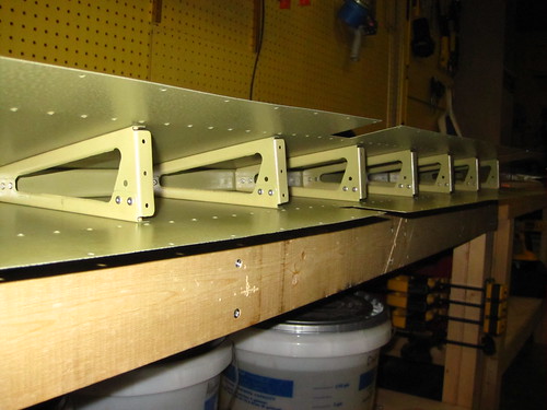
At this point (last night), I had to leave to go take my first night cross country flight, so work was done for the day. Today I got right to priming. As much as I love the golden color of alodined aluminum, it was time to turn everything an ugly olive drab color. The priming process went better this time around and I seemed to get a more even coating. It was a lot colder in the shop this time, since I had to have the door open and a fan blowing out to keep the Akzo haze to a minimum, but it didn't seem to affect the priming process. Here's all of the smaller parts with a fresh coat:
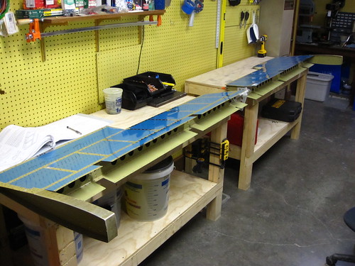
And here are three of the four skins drying:
13 Dec 2009
With the primer dry on all parts, I wasted no time starting the riveting! This is the best part, in my opinion. I like seeing the parts come together into their final configuration.
The first components to go together are the tip ribs and tip rib skins. The right-side one of these went together with no problems. The left-side, unfortunately, was a huge debacle.
For whatever reason, I had my compressor turned up way too high (105psi; the squeezer is rated to 90psi) and neglected to check the spacing between the flush sets before I squeezed the first rivet holding the webs of the two rib sections together. The rivet squeezed down just fine, but the set wouldn't retract. It was totally jammed.
Because it was jammed in the position of being fully extended, I couldn't get it off the part—the flanges were in the way. I tried everything I could to get the set holder to retract into the yoke, but nothing worked.
In the end, I had to bend the two forward flanges down flat to get the yoke off the part, then use a hammer to pound the set holder out of the yoke. It had sheared through completely and jammed itself in the yoke.
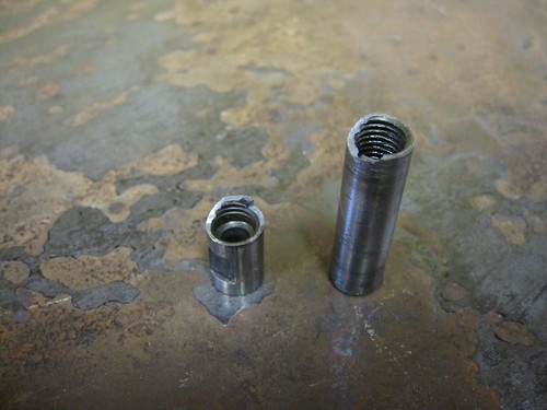
Luckily the $125 yoke was unbent, though the set holder itself was a $55 part. But still, $55 is better than $180. Also, I have a backup (unadjustable) set on hand, so I'll just have to start using shims instead of the twist-to-adjust version.
With the squeezer returned to active status, I worked on finishing up the left-side tip rib assembly. Unfortunately, when I bent the flanges down to extract the yoke, I messed up what was a touchy hole alignment. It took a long time to get them bent back to the point where rivets would push through the holes again. A long, long time. But in the end, they did finally go together and the end result actually looks pretty good.
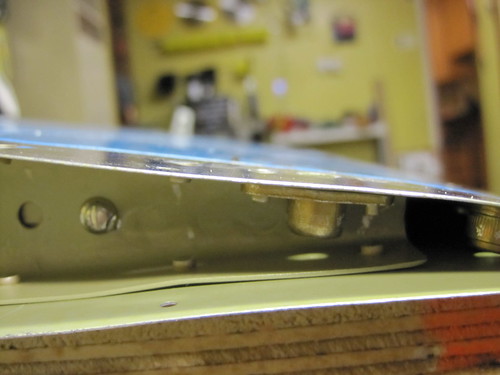
Next up was the hinge doublers on the forward spars. These rivets were all squeezer-accessible, and thus were simple to do and look great. Here's the forward side of one:
And here is the aft side of another one. Notice that there is a rivet missing here. That's because this is the outboard hinge doubler, and this is the hole I will eventually be using for the bonding stud.
Next up was some work at the root ends of the forward spars. The root rib and control arm weldments get riveted on, and this is again all squeezer-friendly. The half-inch inner diameter snap bushings also go in at this point.
Next came the trim tab cable access reinforcement. This consisted of squeezing on seven anchor nuts (which needed to be dimpled first), then back riveting the reinforcement to the skin. The dimpling of the K1100-06 anchor nuts seems a bit odd to me; they don't lie flat on the dimpled plate at all. They do, however, hold in place just fine once riveted and they line up the threads perfectly with the hole, so I guess I can't complain.
Next step was to back rivet in all of the rib halves on all four skins. This went quickly and without incident. Once they were all in place, the rear spar and shar clips are riveted in on the skins that have the larger rib halves installed.
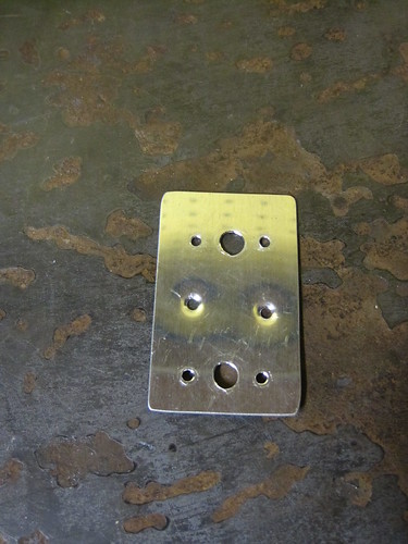
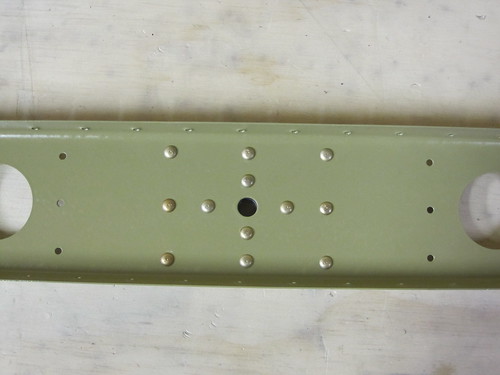
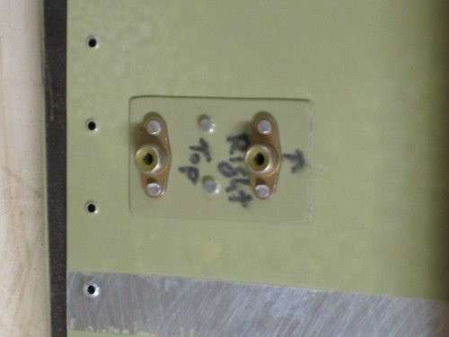
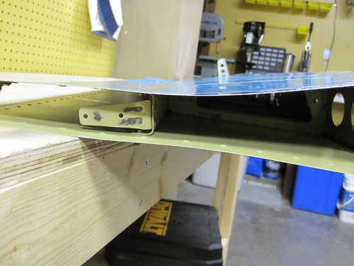
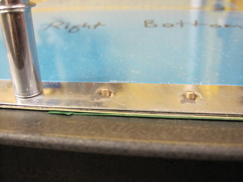
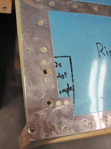
At this point, I went ahead and installed the custom hardware for attaching static wicks to the bottom skins on both sides. This was a reasonably straightforward process; I did it the same way I had done the similar hardware on the rudder. The only difference here was that there were no ribs to act as inherent doublers on three of the four anchor nuts, so I added my homebrew doubler plates. Here is the inboard static wick attachment hardware and its doubler:
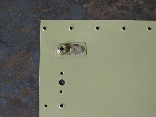
And here is the aft outboard static wick anchor nut and its teeny doubler. The forward outboard anchor nut sits on the tip rib, and will be installed later.
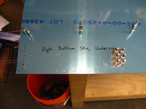
The last thing I did before calling it quits was to rivet the inboard half of the right-side bottom skin to the aft spar. This part can be done with a squeezer. The outboard half of this rivet line requires bucking, so I'll wait until I have help. All-in-all, a huge amount of progress for one day! Having a lot of back-riveting and squeezer-friendly rivets makes things fly by. I should have something good to show off here by the time Friday rolls around and I have my first EAA Technical Counselor visit!
588 rivets today!
16 Dec 2009
The day after tomorrow is my first EAA Technical Counselor visit, and I wanted to have the elevators still open so that he could look at the guts before I closed them up. On the other hand, I'd really like to get the trailing edges sealed before I go on my winter vacation, so that when I come back I can get right back to work. This makes scheduling difficult, since I leave for vacation in five days. Thus, I spent the last few days getting ahead on everything I could without restricting visual access to the inside of the elevator bodies.
I figured it would be OK to rivet the two sides of each elevator together, so long as I left the forward spar off. That would allow me to get a lot further in the plans but still allow my tech counselor to see inside. Bob came over and helped me do the rivet lines that connect the skins to the rear spar. Some of this required the weird custom bucking bar. Luckily, the tool kit I bought from planetools.com came with this part already fabricated, which saved me some serious work. It worked like a charm, and we were able to get all of the rear spar rivets done in about an hour (except for those reserved for the trim tab hinges). With that done, I went ahead and did the 64 blind rivets that attach the two rib halves together:
The next step in the plans was to attach the forward spar assembly, which would prevent the insides of the elevators from being seen. Also, I hadn't finished the ground bonding strap customization that I wanted to add to the forward spar, and this has to be done before the spar is riveted to the ribs. So I put the forward spar attachment on hold and looked at some other tasks I could accomplish instead of moving forward with the plans.
I jumped ahead to the trim tabs and saw that there was one step between priming and applying proseal to the foam inserts. I want to do all of the sealant activities together (for the same reasons that I did all of the priming together), so I went ahead and did the one step necessary on the trim tabs to get them prepared for sealing. This involved riveting the bottom-side rivets between the spar and the skin, and also the seven rivets that attach the control horn halves to the skin. These were all squeezable with the longeron yoke, though some of them were tricky. I also removed the masking tape I had applied before priming so that I have bare scuffed aluminum surfaces to seal the foam to.
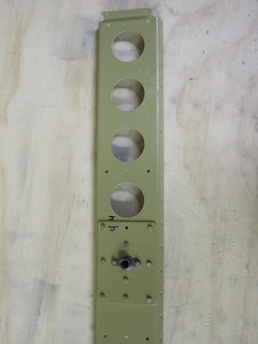
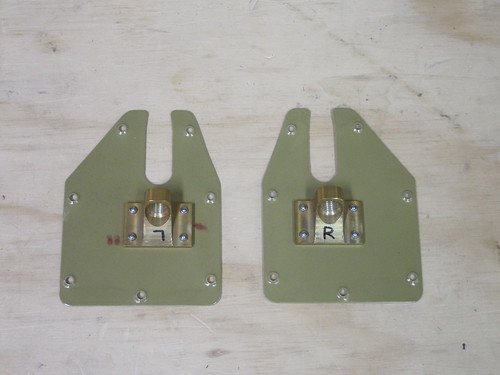
Searching for other things I could work on, I jumped ahead and riveted the trim cable brackets to the access plates:
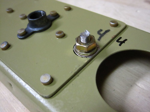
Next I set about installing the bonding strap studs to the outboard hinge doubler using the rivet hole I skipped (the outboard center hole on the doubler). The hardware and philosophy is the same here as it was on the rudder and vertical stabilizer, so I'll just show some shots of the finished product (but before adding epoxy). A more complete photo walkthrough is available in the flickr albumn (just click on any photo). Here is the forward side, where the bonding strap ring termianl and castle nut will attach:
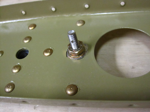
And here is the aft side:
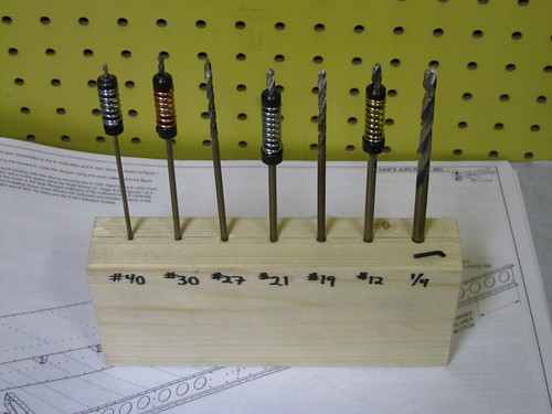
The tasks remaining that don't require either the application of sealant or closing up the elevator bodies is now very small. I still need to countersink the holes in the trailing edge extrusions and put a bend in the trailing edge skins. But that's about it. I'll save that for tomorrow night. Still wanting to get some work done, I set about making a drill bit holder for myself. I've been meaning to do this for some time, but always wanted to just work on the plane instead. This served as a good excuse. Here it is in all its lavish beauty:
21 Dec 2009
The last few days have been rushed; I'm leaving for winter vacation tonight and wanted to get to the point of having all of the elevator trailing edge and foam rib sealant applied so that it could cure while I was gone.
My first EAA technical counselor visit went very well. Will Fox, the local tech counselor, and Jeff Scott, the president of the local EAA chapter, spent about three hours looking over what I had accomplished so far and talking about flying, building, etc. They are a tremendous resource and helped me gain a lot of confidence in what I'm doing. For the most part, they liked what I had built so far, though they pointed out a few rivets that were either over- or under-driven and recommended redoing them. In retrospect, I really should have been more thorough with the rivet gauges.
As soon as they left, I immediately started closing up the elevators so that I could get to the sealant on both the elevator bodies and trim tabs before leaving. The first thing to do was squeeze the rivets connecting the forward spar to the skins. This went quickly as it was all doable with the pneumatic squeezer. Once I got the shims set right, they all squeezed to the same size, so I only had to use the rivet gauges on the first one.
I went ahead and installed the trim cable access plates using the seven screws called out in the plans. This was more to get the plates out of the way than anything else.
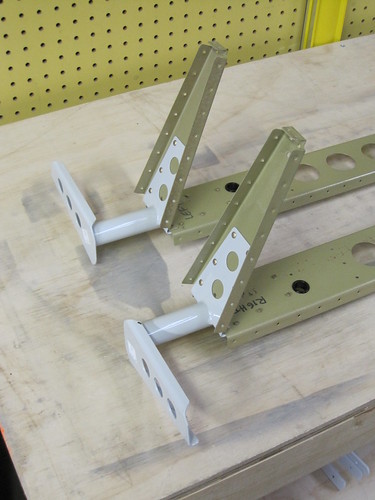
The last big step before I could apply sealant was the tip ribs, and these proved troublesome. For starters, my outboard shear clips were on the wrong side of the aft spars!! How did this happen?
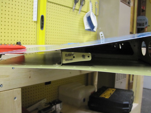
This is really embarrassing. Not only is it clearly shown in the plans what side they need to attach to, but I have markings on the clips that spell it out explicitly as well. The up arrow on the shear clip shown above is pointing towards the bottom skin. Clearly, my attention to detail and double-checking every step still needs some work.
Anyway, I was able to drill/chisel out the two rivets holding each clip in place and re-attach the clips in the correct orientation. This sure would have been easier if I had discovered the mistake before attaching the elevator skins to the spar, though!
With the shear clips in the correct positions, I cleco'd in the tip assemblies and went to work riveting them in. The larger AN470 rivets that attach the tips to the spars and shear clips were a challenge. They had to be bucked and sometimes it involved a bit of contortion to pull it off. Most of the smaller AN426 rivets attaching the skin to the tip assembly were squeezable, though the two inboard rivets behind the forward spar have to be bucked. And to buck them, you have to peel the bottom side skin back, jam your hand and a bucking bar inside from the bottom, while using the rivet gun from the top side. It's tricky, but somehow all four of mine came out great! The corresponding holes on the bottom skin are blind riveted, so that's easy. Here's the final product on one of the top sides:
With the tips in place, the elevators were ready for sealant.
Bob came down after work tonight and in the last hour before I left to drive to Albuquerque to start my vacation, we mixed up some Dynaseal, pasted it all over the foam ribs and trailing edge extrusions, and sealed everything up!
It went considerably better this time around compared with the rudder. For starters, we knew what to expect, so there were no surprises regarding sealant operations. Also, all of the trailing edge clecos stayed in place this time around. I think the difference is that I made the countersinks in the extrusion considerably less deep this time. It made all the difference; no clothes pin nonsense this time.
The trim tab foam ribs are in place with the squeezer blocks on the outside, and the top side clecos are all in place. The trailing edge is weighed down and ready to cure. I'll be back on New Year's Eve!
31 Dec 2009
It's nice to come back to fully-cured sealant and be able to go straight to work! The first thing I did was to pop in the six blind rivets on the close-out tabs in the side between the trim tab and aft end of each elevator. Next, I removed all of the clecos from the trailing edges and cleaned the sealant out of the holes. The clecos went straight into a MEK bath to soak for a few days.
The double-flush rivets of the trailing edges were done in the same manner as the rudder trailing edge, except this time all of my rivets point the same direction. I figured since the bottom side of the elevators isn't ever going to be seen up close except during pre-flight inspections (it's reasonably close to the ground), I might as well concentrate any ugliness there and keep the top side looking pretty.
While populating the top side with AN426-3-3.5 rivets, I skipped three holes (separated by ten holes) for clecos to hold the elevator down to the back riveting bar. I then applied rivet tape and it looked like this:
Next, the part is turned over so that the bottom skin is facing up and the rivet tape is against the back riveting bar. The three holes are lined up with the holes I had made in the bar during the rudder trailing edge. With the elevators cleco'd to the back riveting angle iron, the rivets look like this:
I used a mushroom flush set to drive these. A few taps with the set perpendicular to the workbench drives the rivet into the dimple and prevents it from cleating, then the set is turned to be flush with the skin and the rivet is driven flush. The results look really good, though not quite as pretty as the manufactured heads on the top skin.

The last step is to take out the clecos, populate the three holes with rivets and drive them. These three don't have the benefit of the elevator secured to the plate, so it moves around a bit, but it was still pretty straightforward.
One problem I noticed while doing the trailing edge is that as I got towards the outboard edge, my big mushroom set caused some deformation in the aft end of the tip rib. I wish I had done the tip rib rivets before the trailing edge rivets (even though the tip rib is done afterwards in the plans) to perhaps give this part a bit more structure. Anyway, be careful and gentle (?) when you rivet the last few outboard rivets on the trailing edge!
The next step was to do the rivets that attach the aft end of the tip rib to the skins. These can all be squeezed, though I skipped a couple to make room for the forward outboard static wick attachment anchor nut. Driving these rivets brought some normalcy back into the slightly bent tip rib, though it's still not perfect.
The anchor nut was a serious challenge. The forward rivet was squeezeable with the 4" narrow-head yoke, but the aft rivet had almost no clearance at all. I ended up using a thin chisel as a bucking bar and driving it with the rivet gun. It is almost certainly under-driven, but this is of little concern since this rivet is redundant once the static wick is secured in place.
With the last of the static wick anchor nuts in place, the only thing remaining to do for the static wick customizations on the elevators is to ream out a few of the screw holes so that the holes line up better with the threads beneath. I need to figure out a better way of templating these holes; my rivet holes all line up nicely, but the larger holes never seem to be centered correctly. I'll probably pass this question on to my new EAA friends and see what they have to say.
At this point, it was time to go to a New Year's party, so I called it an evening.
Two days ago, Bob came over and we did a marathon session of match drilling. In about three hours, we knocked out all of the holes in all four skins. It was epic and tedious. And while I'm glad to be through with the match drilling phase of elevator operations, that leaves me unfortunately at the deburring stage which I like even less. Neither of these tasks accomplish much that is photo worthy. Here is a shot of one of the elevators with every skin hole cleco'd:
Last night, while everything was still assembled, I figured out where I wanted to mount the elevator static wicks and worked out the mounting hardware. As with the rudder, the wicks will attach via anchor nuts with elastic inserts. I'll mount the wicks to the bottom skins so that, if I choose to remove them, the mount holes won't be visible. Each elevator gets two wicks, one in line with the outer-most rivet line and one 12 inches inboard from that. The forward anchor nut for the outboard wick is attached thusly:
The aft anchor nut for the outboard wick is off the end of the flage for the tip piece, so it needs a doubler. For clearance reasons with the trailing edge extrusion, I used a one-lug anchor nut and mounted it perpendicular to the foreward anchor nut. I fabricated this small doubler out of a piece of scrap and used it as a template to drill the holes for the aft anchor nut:
The inboard wick has no underlying support rib to take advantage of, so I made a larger doubler that covered both anchor nuts as was able to include a couple of rivet holes just to add support for the doubler.
This doubler was used as a template for the inboard wick mounting holes, which are situated 12 inches inboard of the outboard holes, as per the Dayton Granger recommendations for the RV-10.
With all of the static wick holes drilled, I was done with the first assembly stage of the elevators and called it an evening for last night. Today I disassembled both elevators entirely and started in on the exceedingly dull task of deburring every hole. I managed to get all of the non-skin parts done before being overcome with ennui and calling it a night. Still need to deburr the skins, then it's time to start dimpling!
12 Dec 2009
In the past 10 days, I've procrastinated a lot because the spectre of deburring the skin holes was looming over me and I just didn't want to do it. Every now and then I'd pull one of the four skins out and do one side, but otherwise it became an exercise in seeing how many other tasks on the elevators I could get ahead on without having to have the skins deburred first.
The most significant of these get-ahead tasks was to work on the trim tabs. I intended to do these ahead of schedule anyway since I wanted to prime the parts at the same time that I primed the rest of the elevator bits. So the skin deburring procrastination just gave me another excuse to get on this. With only four parts per tab, they go pretty quickly.
I also got ahead on the alodining process, doing the smaller parts by just dunking them in the storage buckets that I keep the chemicals in. I strung some 18awg solid-core wire across the top and then hung the parts into the liquid from that. It worked great and I was able to drastically reduce the number of parts that needed the huge dunk tank. I didn't want to get the dunk tank out until I was ready to prime, because it's a pain to move and the back of it will be the priming surface.
And with that, I really had nothing left to do but finish the skins, so I sucked it up and got it over with. I was so happy to have finished the deburring that a whirlwind of activity ensued as soon as the last hole was deburred. All of the rivet lines had their vinyl removed on the outer surface, and the inner surface vinyls were entirely removed. All of the holes except the leading edge holes were dimpled. The inner surfaces were scuffed and then cleaned with acetone (note to self: next time scuff and clean BEFORE dimpling; the dimples tear up the scotchbrite pads).
The dunk tank was set up as before, and the length set to a few inches longer than the forward elevator spar. I lined it with 4 mil plastic sheet again and added the alumiprep and distilled water. I recycled the distilled water from last time even though it was quite yellow from alodine. When all of the parts had been etched with the alumiprep, I emptied that trough and replaced it with alodine. The same process was repeated with the alodine and then all of the parts were hung up to dry.
At this point (last night), I had to leave to go take my first night cross country flight, so work was done for the day. Today I got right to priming. As much as I love the golden color of alodined aluminum, it was time to turn everything an ugly olive drab color. The priming process went better this time around and I seemed to get a more even coating. It was a lot colder in the shop this time, since I had to have the door open and a fan blowing out to keep the Akzo haze to a minimum, but it didn't seem to affect the priming process. Here's all of the smaller parts with a fresh coat:
And here are three of the four skins drying:
13 Dec 2009
With the primer dry on all parts, I wasted no time starting the riveting! This is the best part, in my opinion. I like seeing the parts come together into their final configuration.
The first components to go together are the tip ribs and tip rib skins. The right-side one of these went together with no problems. The left-side, unfortunately, was a huge debacle.
For whatever reason, I had my compressor turned up way too high (105psi; the squeezer is rated to 90psi) and neglected to check the spacing between the flush sets before I squeezed the first rivet holding the webs of the two rib sections together. The rivet squeezed down just fine, but the set wouldn't retract. It was totally jammed.
Because it was jammed in the position of being fully extended, I couldn't get it off the part—the flanges were in the way. I tried everything I could to get the set holder to retract into the yoke, but nothing worked.
In the end, I had to bend the two forward flanges down flat to get the yoke off the part, then use a hammer to pound the set holder out of the yoke. It had sheared through completely and jammed itself in the yoke.
Luckily the $125 yoke was unbent, though the set holder itself was a $55 part. But still, $55 is better than $180. Also, I have a backup (unadjustable) set on hand, so I'll just have to start using shims instead of the twist-to-adjust version.
With the squeezer returned to active status, I worked on finishing up the left-side tip rib assembly. Unfortunately, when I bent the flanges down to extract the yoke, I messed up what was a touchy hole alignment. It took a long time to get them bent back to the point where rivets would push through the holes again. A long, long time. But in the end, they did finally go together and the end result actually looks pretty good.
Next up was the hinge doublers on the forward spars. These rivets were all squeezer-accessible, and thus were simple to do and look great. Here's the forward side of one:
And here is the aft side of another one. Notice that there is a rivet missing here. That's because this is the outboard hinge doubler, and this is the hole I will eventually be using for the bonding stud.
Next up was some work at the root ends of the forward spars. The root rib and control arm weldments get riveted on, and this is again all squeezer-friendly. The half-inch inner diameter snap bushings also go in at this point.
Next came the trim tab cable access reinforcement. This consisted of squeezing on seven anchor nuts (which needed to be dimpled first), then back riveting the reinforcement to the skin. The dimpling of the K1100-06 anchor nuts seems a bit odd to me; they don't lie flat on the dimpled plate at all. They do, however, hold in place just fine once riveted and they line up the threads perfectly with the hole, so I guess I can't complain.
Next step was to back rivet in all of the rib halves on all four skins. This went quickly and without incident. Once they were all in place, the rear spar and shar clips are riveted in on the skins that have the larger rib halves installed.
At this point, I went ahead and installed the custom hardware for attaching static wicks to the bottom skins on both sides. This was a reasonably straightforward process; I did it the same way I had done the similar hardware on the rudder. The only difference here was that there were no ribs to act as inherent doublers on three of the four anchor nuts, so I added my homebrew doubler plates. Here is the inboard static wick attachment hardware and its doubler:
And here is the aft outboard static wick anchor nut and its teeny doubler. The forward outboard anchor nut sits on the tip rib, and will be installed later.
The last thing I did before calling it quits was to rivet the inboard half of the right-side bottom skin to the aft spar. This part can be done with a squeezer. The outboard half of this rivet line requires bucking, so I'll wait until I have help. All-in-all, a huge amount of progress for one day! Having a lot of back-riveting and squeezer-friendly rivets makes things fly by. I should have something good to show off here by the time Friday rolls around and I have my first EAA Technical Counselor visit!
588 rivets today!
16 Dec 2009
The day after tomorrow is my first EAA Technical Counselor visit, and I wanted to have the elevators still open so that he could look at the guts before I closed them up. On the other hand, I'd really like to get the trailing edges sealed before I go on my winter vacation, so that when I come back I can get right back to work. This makes scheduling difficult, since I leave for vacation in five days. Thus, I spent the last few days getting ahead on everything I could without restricting visual access to the inside of the elevator bodies.
I figured it would be OK to rivet the two sides of each elevator together, so long as I left the forward spar off. That would allow me to get a lot further in the plans but still allow my tech counselor to see inside. Bob came over and helped me do the rivet lines that connect the skins to the rear spar. Some of this required the weird custom bucking bar. Luckily, the tool kit I bought from planetools.com came with this part already fabricated, which saved me some serious work. It worked like a charm, and we were able to get all of the rear spar rivets done in about an hour (except for those reserved for the trim tab hinges). With that done, I went ahead and did the 64 blind rivets that attach the two rib halves together:
The next step in the plans was to attach the forward spar assembly, which would prevent the insides of the elevators from being seen. Also, I hadn't finished the ground bonding strap customization that I wanted to add to the forward spar, and this has to be done before the spar is riveted to the ribs. So I put the forward spar attachment on hold and looked at some other tasks I could accomplish instead of moving forward with the plans.
I jumped ahead to the trim tabs and saw that there was one step between priming and applying proseal to the foam inserts. I want to do all of the sealant activities together (for the same reasons that I did all of the priming together), so I went ahead and did the one step necessary on the trim tabs to get them prepared for sealing. This involved riveting the bottom-side rivets between the spar and the skin, and also the seven rivets that attach the control horn halves to the skin. These were all squeezable with the longeron yoke, though some of them were tricky. I also removed the masking tape I had applied before priming so that I have bare scuffed aluminum surfaces to seal the foam to.
Searching for other things I could work on, I jumped ahead and riveted the trim cable brackets to the access plates:
Next I set about installing the bonding strap studs to the outboard hinge doubler using the rivet hole I skipped (the outboard center hole on the doubler). The hardware and philosophy is the same here as it was on the rudder and vertical stabilizer, so I'll just show some shots of the finished product (but before adding epoxy). A more complete photo walkthrough is available in the flickr albumn (just click on any photo). Here is the forward side, where the bonding strap ring termianl and castle nut will attach:
And here is the aft side:
The tasks remaining that don't require either the application of sealant or closing up the elevator bodies is now very small. I still need to countersink the holes in the trailing edge extrusions and put a bend in the trailing edge skins. But that's about it. I'll save that for tomorrow night. Still wanting to get some work done, I set about making a drill bit holder for myself. I've been meaning to do this for some time, but always wanted to just work on the plane instead. This served as a good excuse. Here it is in all its lavish beauty:
21 Dec 2009
The last few days have been rushed; I'm leaving for winter vacation tonight and wanted to get to the point of having all of the elevator trailing edge and foam rib sealant applied so that it could cure while I was gone.
My first EAA technical counselor visit went very well. Will Fox, the local tech counselor, and Jeff Scott, the president of the local EAA chapter, spent about three hours looking over what I had accomplished so far and talking about flying, building, etc. They are a tremendous resource and helped me gain a lot of confidence in what I'm doing. For the most part, they liked what I had built so far, though they pointed out a few rivets that were either over- or under-driven and recommended redoing them. In retrospect, I really should have been more thorough with the rivet gauges.
As soon as they left, I immediately started closing up the elevators so that I could get to the sealant on both the elevator bodies and trim tabs before leaving. The first thing to do was squeeze the rivets connecting the forward spar to the skins. This went quickly as it was all doable with the pneumatic squeezer. Once I got the shims set right, they all squeezed to the same size, so I only had to use the rivet gauges on the first one.
I went ahead and installed the trim cable access plates using the seven screws called out in the plans. This was more to get the plates out of the way than anything else.
The last big step before I could apply sealant was the tip ribs, and these proved troublesome. For starters, my outboard shear clips were on the wrong side of the aft spars!! How did this happen?
This is really embarrassing. Not only is it clearly shown in the plans what side they need to attach to, but I have markings on the clips that spell it out explicitly as well. The up arrow on the shear clip shown above is pointing towards the bottom skin. Clearly, my attention to detail and double-checking every step still needs some work.
Anyway, I was able to drill/chisel out the two rivets holding each clip in place and re-attach the clips in the correct orientation. This sure would have been easier if I had discovered the mistake before attaching the elevator skins to the spar, though!
With the shear clips in the correct positions, I cleco'd in the tip assemblies and went to work riveting them in. The larger AN470 rivets that attach the tips to the spars and shear clips were a challenge. They had to be bucked and sometimes it involved a bit of contortion to pull it off. Most of the smaller AN426 rivets attaching the skin to the tip assembly were squeezable, though the two inboard rivets behind the forward spar have to be bucked. And to buck them, you have to peel the bottom side skin back, jam your hand and a bucking bar inside from the bottom, while using the rivet gun from the top side. It's tricky, but somehow all four of mine came out great! The corresponding holes on the bottom skin are blind riveted, so that's easy. Here's the final product on one of the top sides:
With the tips in place, the elevators were ready for sealant.
Bob came down after work tonight and in the last hour before I left to drive to Albuquerque to start my vacation, we mixed up some Dynaseal, pasted it all over the foam ribs and trailing edge extrusions, and sealed everything up!
It went considerably better this time around compared with the rudder. For starters, we knew what to expect, so there were no surprises regarding sealant operations. Also, all of the trailing edge clecos stayed in place this time around. I think the difference is that I made the countersinks in the extrusion considerably less deep this time. It made all the difference; no clothes pin nonsense this time.
The trim tab foam ribs are in place with the squeezer blocks on the outside, and the top side clecos are all in place. The trailing edge is weighed down and ready to cure. I'll be back on New Year's Eve!
31 Dec 2009
It's nice to come back to fully-cured sealant and be able to go straight to work! The first thing I did was to pop in the six blind rivets on the close-out tabs in the side between the trim tab and aft end of each elevator. Next, I removed all of the clecos from the trailing edges and cleaned the sealant out of the holes. The clecos went straight into a MEK bath to soak for a few days.
The double-flush rivets of the trailing edges were done in the same manner as the rudder trailing edge, except this time all of my rivets point the same direction. I figured since the bottom side of the elevators isn't ever going to be seen up close except during pre-flight inspections (it's reasonably close to the ground), I might as well concentrate any ugliness there and keep the top side looking pretty.
While populating the top side with AN426-3-3.5 rivets, I skipped three holes (separated by ten holes) for clecos to hold the elevator down to the back riveting bar. I then applied rivet tape and it looked like this:
Next, the part is turned over so that the bottom skin is facing up and the rivet tape is against the back riveting bar. The three holes are lined up with the holes I had made in the bar during the rudder trailing edge. With the elevators cleco'd to the back riveting angle iron, the rivets look like this:
I used a mushroom flush set to drive these. A few taps with the set perpendicular to the workbench drives the rivet into the dimple and prevents it from cleating, then the set is turned to be flush with the skin and the rivet is driven flush. The results look really good, though not quite as pretty as the manufactured heads on the top skin.
The last step is to take out the clecos, populate the three holes with rivets and drive them. These three don't have the benefit of the elevator secured to the plate, so it moves around a bit, but it was still pretty straightforward.
One problem I noticed while doing the trailing edge is that as I got towards the outboard edge, my big mushroom set caused some deformation in the aft end of the tip rib. I wish I had done the tip rib rivets before the trailing edge rivets (even though the tip rib is done afterwards in the plans) to perhaps give this part a bit more structure. Anyway, be careful and gentle (?) when you rivet the last few outboard rivets on the trailing edge!
The next step was to do the rivets that attach the aft end of the tip rib to the skins. These can all be squeezed, though I skipped a couple to make room for the forward outboard static wick attachment anchor nut. Driving these rivets brought some normalcy back into the slightly bent tip rib, though it's still not perfect.
The anchor nut was a serious challenge. The forward rivet was squeezeable with the 4" narrow-head yoke, but the aft rivet had almost no clearance at all. I ended up using a thin chisel as a bucking bar and driving it with the rivet gun. It is almost certainly under-driven, but this is of little concern since this rivet is redundant once the static wick is secured in place.
With the last of the static wick anchor nuts in place, the only thing remaining to do for the static wick customizations on the elevators is to ream out a few of the screw holes so that the holes line up better with the threads beneath. I need to figure out a better way of templating these holes; my rivet holes all line up nicely, but the larger holes never seem to be centered correctly. I'll probably pass this question on to my new EAA friends and see what they have to say.
At this point, it was time to go to a New Year's party, so I called it an evening.
| <-- November 2009 | January 2010 --> |