
| Workshop | Empennage | Wings | Fuselage | Contact |
| <-- September 2009 | November 2009 --> |
Chronological Updates, October 2009
5 Oct 2009
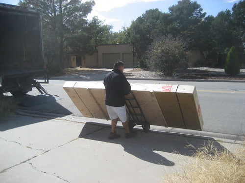
This past Friday I called down to ABF freight and discovered that, not only had my empennage kit shipped, but that it was already in Albuquerque. Unfortunately, they only deliver to Los Alamos once a week, so it wouldn't be delivered to my house until this coming Thursday. I asked how large the crate was and they gave me a figure that was different from what Van's website lists and also small enough to conceiveably fit in my truck. I drove down to Albuquerque to retrieve the kit.

Unfortunately, they were wrong about the size and it would not fit into my truck. Also, the crate has already suffered some damage. I didn't want to be responsible for any phase of transportation of a damaged crate, so I left it there and resigned to waiting a week for my kit.
I spent some time this weekend putting together a wiring block diagram for the tail of the airplane. Click here for a PDF showing my current thinking. This only covers the aft-end of the tailcone and the various tail feathers. Hopefully, planning these wire runs ahead will help me to not have to run wires down the tailcone after it is buttoned up, etc.
8 Oct 2009
The big day! The empennage kit has been delivered!
While the delivery guy was still there, we opened up the crate and had a look around for damage due to the cracked crate. Couldn't find any sign of damage whatsoever. What a relief!
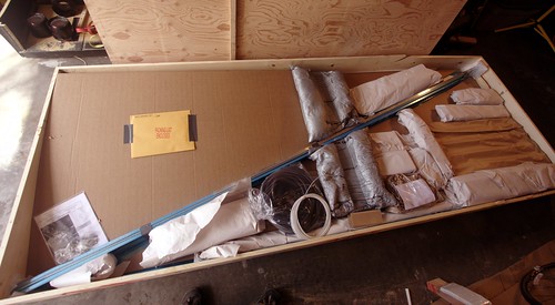
After the delivery I had to go back to work. But as soon as I got home I tore right into the inventory. Finished the inventory five hours later. Every part accounted for and undamaged.
Total time spent on this effort was five hours. For more photos of the inventory, see the associated flickr gallery.
9 Oct 2009
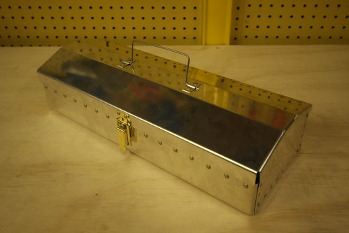
Today I learned how to rivet. I spent most of the day not working on the RV-10. I wanted to knock out Van's toolbox kit first, which taught me a lot about sheet metal work. In particular, this was my first exposure to riveting. In fact, here is my first rivet ever:
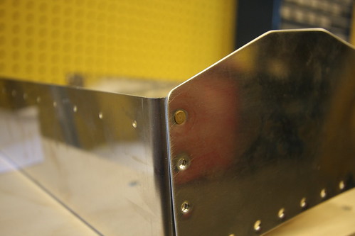
I think it came out pretty well. I did mess up a lot of rivets, mostly on the one side panel that I forgot (how??) to cleco to the main body before riveting on. Wow. Yeah that doesn't work. All of my squeezed rivets, cupped and flush, look awesome with the exception of one where I slipped just as I pulled the trigger on the squeezer. My rivet gun rivets aren't nearly as nice, but they got noticably better as I finished the box. Here's the final product:
After finishing the box I drove down to Santa Fe for a flight lesson, and what I thought might be my first solo. But it suddenly got so windy that we decided not to fly at all and just walked around the ramp at SAF looking at all the planes. I did manage to put in one whole hour of actual work on the plane—my first actual hour of construction work!
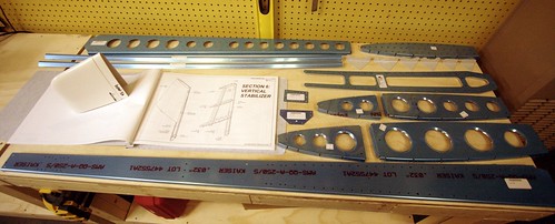
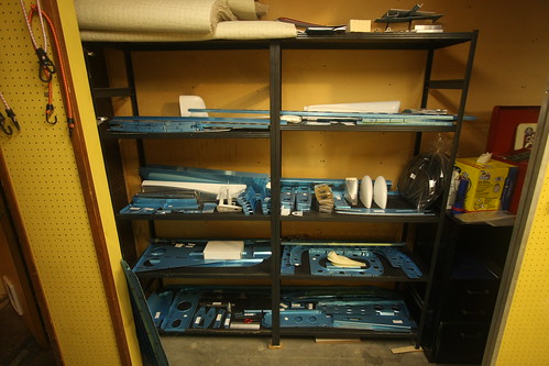
I grabbed all of the vertical stabilizer parts off of the shelf I had reserved for this subassembly, and was pleased to find that everything called out in the plans was there where it should have been. Score one for thorough inventory last night.
A lot of builders have commented on consternation regarding the first step, the long bandsaw cuts on the rear spar caps (VS-1014). I had some concern as well, but mostly because my bandsaw doesn't list aluminum as one of the things it would cut. During the toolbox construction, I tested this by cutting the aluminum hinge to length on the bandsaw and it went through it like butter... so I guessed I was probably good to go on the spar caps. The cuts took a long time but came out looking great.
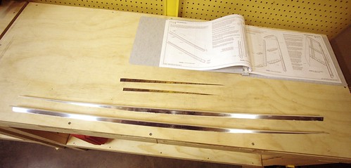
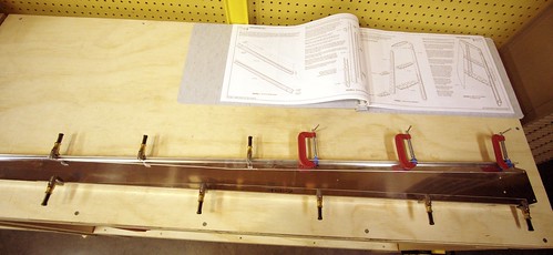
I did all of the deburring of these two parts on the scotchbrite wheel which went very quickly. The only problem was the enormous amount of warp! It made it hard to mark a straight line (because I had to have the thing clamped in four places to the workbench in order to keep it straight, and the clamps got in the way of the straightedge). It also makes the beginning of step 2 interesting, where you are supposed to nest the spar caps inside the flange of the rear spar. It took 11 clamps before I felt like the spar caps were sitting where they should be in the spar.
That's it for my first day of real construction work. Just one hour.
10 Oct 2009
My 4-day weekend of plane building continues. Spent about 8 hours today on the vertical stabilizer. First up was finishing §6.2.2 which I had started last night. With all the clamps in place, the bendy spar caps weren't an issue. It did require the use of a 1/8" drill bit, which was not included in my tool kit from planetools.com. I thought about just using a #30, which is close, but saw that the instructions have me coming back through with a #30 later for final drilling and figured there's probably a reason. So I ran to the hardware store and picked up a new bit (the only 1/8" bit I had was a wood-cutting bit).
Step three took a ton of time, because for whatever reason I decided to put a cleco in every hole as I went, so when I had to remove the spar caps to deburr the holes, I had to take out about 100 clecos. And then I put them all back in again like a doofus. Look at this ridiculous thing:
The spar doubler cleaned up nicely on the scotchbrite wheel, though I couldn't do the interior surfaces. Those I worked with a file and broke the edges with a pencil deburring tool. As you can see, this time I was a bit more frugal with the clecos (partially because the spar doubler was considerably less bent than the caps).
At this point I removed everything except the caps and deburred all holes. I neglected to mark which hinge half was which before taking them off and had to reassemble them and check before continuing. Small oops, but no biggie. With the hinge parts finished and not needed for the rest of assembly, I left them off along with the VS-1017 hinge doubler for the remainder of today's work. This allowed the vertical stabilizer to lay flat on the aft side of its rear spar, making working on the skeleton and skins easier. The next step was to machine countersink the spar doubler and this was where I made my first significant oops. I got so involved with figuring out where to set the countersink cage for proper depth that I forgot that I only wanted to countersink the holes beneath the upper attach bolt holes. I countersunk eight of the wrong holes before I realized my mistake. Hopefully I can just use AN426 flush rivets here instead of the AN470 called out in the plans. I'll fire off an email to Van's and confirm this. Otherwise, I'll have to order and refabricate a new spar doubler and that will be a pain. For now, this mistake does not prevent me from continuing with the fabrication of the vertical stabilizer. Not a great way to finish my first page of the plans, but that's it! Page §6.2 complete (sort of)!
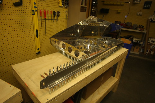
I deburred the rest of the skeleton parts on the scotchbrite wheel and used the pencil tool on the lightening holes. Worked great. Paid special attention to the nose rib points, which I ground down about 3/16" so as not to dimple the skin leading edge when I fold it over the skeleton. Onec that was done, I went ahead and assembled the skeleton with the rear spar clamped to a leg of my workbench:
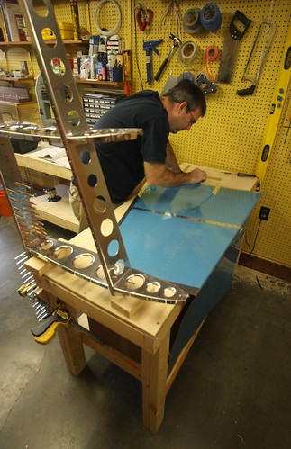
It was really wobbly. It was really disconcerting how little structural stability this skeleton has with no skin on it. Whereas the rear spar is solid as a rock with those caps and doubler in there, the rest of the parts are just wibbly and I feel like it was going to fold under its own weight. Yikes. Anyway, I thought it would be cool to work on the assembly in its natural upright position, but this came to a rapid end as I needed to final drill those holes on the top rib where it connects to the front spar, and with it clamped to the bench like this, those holes were about six feet off the floor! It made for a cool picture, anyway.
Back on the table, I got the skeleton final drilling out of the way and prepared to put the skin on! First, I had to remove the vinyl from the inside surface. This proved to be harder than I thought it would be. Removing the vinyl from the other parts had been reasonably straightforward. Here I ended up having to wrap the vinyl around a broom handle and rolling that up to pull the coating off. It seemed a lot more sticky than the other parts. Took about 10 minutes just to get the vinyl off that one part. Then, another short bit of instructions that takes forever. "Clecko the skin to the skeleton" translated into about two hours of work. I'm not sure why I had such a hard time with this, but everything I was trying was not working. The hardest part was getting the holes to line up on the middle nose rib. In the end, what worked the best was doing the clecos on one side for everything but the middle nose rib, then turning the assembly over.
Next, I helt a cleco in the hole for the forward-most hole in the skin for the nose rib, then with my other arm I reached under the skin and wiggled the rib back and forth until I got the cleco to drop. It was a giant pain, but it was only required for the five or six rivets on the one side of that nose rib. Once that was done, everything else went into place pretty easily. I finished up with clecoing the skin to the skeleton and called it a night. The result looked something like this:
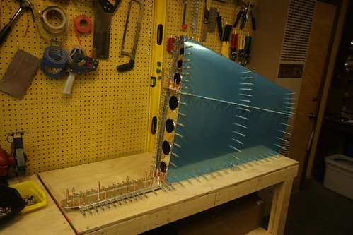
It's nice to have something that vaguely resembles a plane part on the bench! Also, it was pleasing to note that with the skin on, the stabilizer was rock solid, not the miserable flimsy thing the skeleton had been. First thing tomorrow will be §6.3.4: match-drilling each and every hole in the skin. Unfortunately, after that step, the whole assembly comes apart again for awhile.
11 Oct 2009
Most of the six hours of work that got done today involved things that don't have much visual impact on the vertical stabilizer at all. A lot of dimpling, deburring, and match-drilling parts that were already together. Probably the most visually striking thing that happened was when I removed some strips of vinyl from the front of the VS skin. Bob came by to check out the project so I put him to work helping me get the vinyl strips off.
Aside from the vinyl modification, I got all of the skin holes match drilled and deburred. I also deburred all of the skin/skeleton interface holes on the skeleton. I then started the dimpling. Got all of the skeleton holes dimpled, but gave up on trying to dimple the skin by myself since Bob said he'd help over lunch tomorrow and it'll be a lot easier with two people. The skeleton dimpling required all three of my available dimpling techniques! Most of it was done on the DRDT-2 dimpler (which I love), but a few of the corner holes and holes in the narrow pieces wouldn't work there, so I broke out the pneumatic squeezer and took care of the rest—except for the forward two holes on the top rib, for which even the squeezer wouldn't do. For these, I had to use the pop rivet tool and the nail/dimple die combo. Worked like a champ.
Also took care of countersinking the rear spar/skin interface holes where called out in §6.3.8. With the exception of the skin dimples, the next step is to disassemble the rear spar bits. This will be the last time the spar is together before the parts are primed, so I am likely to hold on doing §6.3.9 until I figure out a few of the customizations I'm going to be adding to this subassembly. In particular, I need to figure out where and how to mount the braided copper grounding straps that will run between the VS and the rudder.
12 Oct 2009
The last day of my four day RV-10 superweekend.
Spent the morning finishing minor tasks like preparing the rudder stops and match-drilling the hinges, etc. When Bob showed up on his lunchbreak, we made quick work of the skin dimpling. The very front hole in the middle rib was not reachable with the DRDT-2 so I had to pop-dimple that one. Otherwise we knocked it out in about 10 minutes and went out for Chinese food.
Spent the rest of the day working on some custom parts for my electrical run to the vertical stabilizer fairing. I know I want to mount a camera up there someday, and I have vague notions of someday flying internationally with this thing which means I may need an HF antenna—the top of the tail is a logical place for one end of a longwire antenna on a plane. So I'm running a harness of cables from inside the VS fairing to the base of the VS with circular plastic connectors on each end to facilitate hooking up accessories in the future without having to do a tricky cable run. I also am going to run an empty conduit up to the top in case I want to run an antenna cable but don't want to have lossy connectors in line.
To pull this off, I need doublers at both the top and bottom nose ribs and some way to keep the conduit and cables off the lightening hole edges on the middle nose rib.
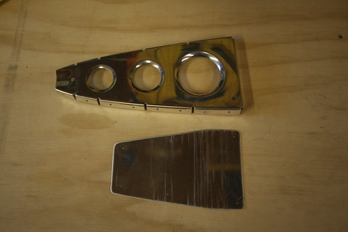
Here is the doubler plate I whipped up for the bottom nose rib. I know it's unnecessarily huge... but whatever it's light. I drilled out holes for the connector and conduit, and rivet holes to attach it to the nose rib and ended up something like this:
For the middle nose rib I found the perfect product—a wire tie bracket made especially for riveting onto lightening holes. How perfect? I just had to drill two small rivet holes in the middle nose rib.
For the top rib I had to make a much more compact doubler since the rib itself is so small. I had concerns about so many holes in such a small piece, but the technical support people at Van's said they didn't forsee any problem with this.
That's about it for today. Only about five hours of actual work. At this point, I am at §6.4.5 which states, simply, "prime the parts." This is going to take some infrastructure preparation so it may be awhile before significant progress occurs on the vertical stab.
17 Oct 2009
The vertical stabilizer parts are all fabricated and awaiting primer, but I need to get some long lumber to make my part prep tanks and I don't have access to my truck this week. So I shelved the VS parts and started on the rudder. No marathon sessions this week, just an hour here and there. Total of about four hours over various lunch breaks and after dinner cleco sessions.
The first step was to lay out all of the rudder parts for a group shot. The only thing missing here is the electrical connectors, wire, and skins.
Just like with the vertical stabilizer, the rudder starts out with some bandsaw cuts. In this case, a bunch of smaller pieces are joined together with little tabs for ease of manufacturing. It was a reasonably quick piece of work to turn seven identical pieces of angle aluminum and three other punched sheets into these 25 parts:
The pieces for the rudder went together astonishingly quickly; it didn't take long at all to get to the point where I was putting skins on for the first time.
The last thing I did before leaving town for the weekend was put the second skin on in preparation for final drilling.
At this point, I'll probably just finish up with the final drilling and dimpling of all rudder pieces and do all of the priming of both VS and rudder together in one shot to minimize painting overhead.
19 Oct 2009
Over the last two days, I've put in four more hours preparing parts for the rudder. Despite the relatively small number of hours, some significant work was accomplished.
I match drilled all of the holes in the rudder skin, then disassembled the rudder completely and deburred all of the skeleton parts and dimpled the ribs, stiffeners, and spar. I also made some changes for the planned electrical wiring within the rudder.
The plan is to have a wire bundle hanging out the back end of the tailcone beneath the bottom of the lower rudder rib but above the bottom of the lower rudder fairing. A hole will be made in the lower fairing that will allow this cable to enter the fairing during normal operation. The wire will connect to a circular plastic connector attached to the bottom of the lower rudder rib, and from there the cables will split into two groups. The first group will just connect to the tail light at the aft end of the fairing. The second group will pass through a snap bushing in the lower rib and then travel up through three of the stiffeners to the area where the rudder trim modification will eventually be made.
For the time being, the wire bundle will just end in another CPC between the C and D stiffeners. I'll make the cuts for the rudder trim after the rudder has been riveted together. In order to safely pass the wires through the triangular holes in the stiffeners, I drilled out one of the unused holes in each of the left side stiffeners to which I plan to rivet some of the lightening hole wire tie attach brackets. These should keep the wires out of contact with the metal. Thus, the modifications to the three stiffeners were composed simply of final drilling three holes.
The lower rib was a bit more complex. First I fabricated a small angle flange to attach the CPC to.
This, in turn, will get riveted to the bottom side of the lower rib.
Finally, a 3/8" hole was drilled aft of the CPC flange in the lower rib for the snap bushing through which the trim servo wires will pass. That's it for parts fabrication for the rudder wiring. I disassembled the lower rib and modified flanges, deburred everything, and dimpled them where appropriate.
All that remains before priming of the rudder is to make the bend at the trailing edges of the skins, deburr the skins, and dimple the skins.
20 Oct 2009
Nothing momentous happened today; spent about an hour deburring both sides of both rudder skins. Need to figure out the right way to make the bend in the trailing edge before I proceed to dimpling.
29 Oct 2009
A bunch of random things have occurred in the last week. After reading up on other builders websites, I determined that I wouldn't be making the bend in the trailing edge of the rudder at all. I'll be using the angle iron backrivet technique and tank sealant to ensure a good bond at the trailing edge.
Making this decision cleared me to finish up the rudder skins. I removed the vinyl coating from the rivet lines and Bob assisted with the dimpling of all the holes. The next step on the skins will be to scuff the inner surface, clean it, and then prime it.
I spent a lot of time thinking about how to do bond straps between the rudder and vertical stab. I was unable to find appropriate ring terminals, bolts, washers, and nuts in aluminum... so I've decided to use passivated cadmium-plated steel hardware instead and hope for the best. I ordered some candidate pieces from Aircraft Spruce and they look like they might work. I also ordered hardware for making the vertical stabilizer and lower rudder fairings removable via nutplates. Unfortunately I based my parts decisions here on another builder's website who had a typo in their part numbers! I ordered thirty K1000-6 nutplates instead of K1000-06 nutplates without checking the bolt size vs. nutplate size. That's a $50 oops! Reordered the correct nutplates from Van's. They'll be here long before I'm ready for them. If anyone needs any of the huge K1000-6 nutplates... let me know.
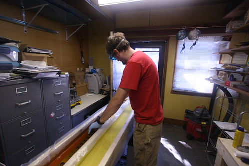
The other major accomplishment of this week was building the dunk tank for doing alumiprep and alodine chemistry on the long thin parts of the aircraft. I didn't want to have to build more than one of these, so I made it really long to accomodate the longest pieces of the airplane. Right now, the longest parts I know of are the horizontal stabilizer spars, which come in at about 11'6" each. I bought three twelve foot 2x4s and made a simple double-trough frame out of them. I used the plywood from the empennage delivery crate for the bottom of the troughs, and a four foot spare piece of 2x4 from the workbench assembly for the end caps. Drilled drain holes in one end and fashioned a couple of 2x4 blocks to allow for length customization, saving on chemical volume when working on parts shorter than the horizontal stabilizer spars.
Above is a picture of the finished dunk tank with the length blocks set at about six feet, just longer than the longest parts in both the rudder and vertical stabilizer. I then lined the active side of the tank with 4 mil plastic sheet and poked it down through the drain holes. I used a staple gun to temporarily keep the sheet in place. The dunk tank is ready to go! More pictures here.
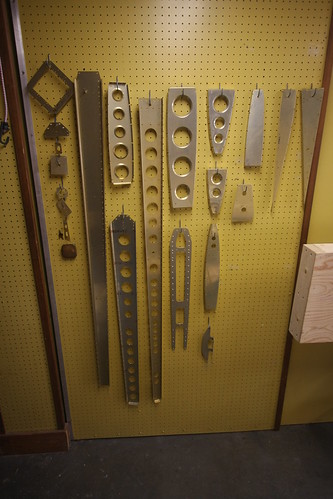
The last thing I did was to rig up hooks and line for allowing the parts to air dry after the alumiprep and alodine washes are complete. Currently all of the parts for both the vertical stabilizer and rudder and hanging in the shop. The only thing I'm missing before I proceed with the chemistry is buckets to reclaim the used water and chemicals. Should be able to pick those up at the local hardware store. Then, it'll be time for SCIENCE!
31 Oct 2009
Got three sealable five-gallon buckets this morning, one for alodine, one for alumiprep, and one for distilled water. The Alodine comes by the gallon and gets mixed 1:2 with water, for a total of three gallons of solution. The Alumiprep also comes by the gallon and gets mixed 1:3 with water, for four gallons of solution. I pre-mixed these and labeled their respective buckets.
With the adjustable blocks in my dunk tank set at just over five feet (the length of the rudder spar), and each trough being six inches wide, three gallons was enough for an almost two inch deep pool of Alodine. I only used about three gallons of the Alumiprep as well.
The process of immersing the parts in each bath and then drying went surprisingly quickly. I was able to prep and alodine all of the parts for both the vertical stabilizer and rudder in about two hours including setup and cleanup. Also, this was my first time figuring out how everything would work, so I took a lot longer on some steps than I will require when I do this again for the horizontal stabilizer.
All of the parts now have that great golden finish to them and are ready for priming.
This past Friday I called down to ABF freight and discovered that, not only had my empennage kit shipped, but that it was already in Albuquerque. Unfortunately, they only deliver to Los Alamos once a week, so it wouldn't be delivered to my house until this coming Thursday. I asked how large the crate was and they gave me a figure that was different from what Van's website lists and also small enough to conceiveably fit in my truck. I drove down to Albuquerque to retrieve the kit.
Unfortunately, they were wrong about the size and it would not fit into my truck. Also, the crate has already suffered some damage. I didn't want to be responsible for any phase of transportation of a damaged crate, so I left it there and resigned to waiting a week for my kit.
I spent some time this weekend putting together a wiring block diagram for the tail of the airplane. Click here for a PDF showing my current thinking. This only covers the aft-end of the tailcone and the various tail feathers. Hopefully, planning these wire runs ahead will help me to not have to run wires down the tailcone after it is buttoned up, etc.
8 Oct 2009
The big day! The empennage kit has been delivered!
While the delivery guy was still there, we opened up the crate and had a look around for damage due to the cracked crate. Couldn't find any sign of damage whatsoever. What a relief!
After the delivery I had to go back to work. But as soon as I got home I tore right into the inventory. Finished the inventory five hours later. Every part accounted for and undamaged.
Total time spent on this effort was five hours. For more photos of the inventory, see the associated flickr gallery.
9 Oct 2009
Today I learned how to rivet. I spent most of the day not working on the RV-10. I wanted to knock out Van's toolbox kit first, which taught me a lot about sheet metal work. In particular, this was my first exposure to riveting. In fact, here is my first rivet ever:
I think it came out pretty well. I did mess up a lot of rivets, mostly on the one side panel that I forgot (how??) to cleco to the main body before riveting on. Wow. Yeah that doesn't work. All of my squeezed rivets, cupped and flush, look awesome with the exception of one where I slipped just as I pulled the trigger on the squeezer. My rivet gun rivets aren't nearly as nice, but they got noticably better as I finished the box. Here's the final product:
After finishing the box I drove down to Santa Fe for a flight lesson, and what I thought might be my first solo. But it suddenly got so windy that we decided not to fly at all and just walked around the ramp at SAF looking at all the planes. I did manage to put in one whole hour of actual work on the plane—my first actual hour of construction work!
I grabbed all of the vertical stabilizer parts off of the shelf I had reserved for this subassembly, and was pleased to find that everything called out in the plans was there where it should have been. Score one for thorough inventory last night.
A lot of builders have commented on consternation regarding the first step, the long bandsaw cuts on the rear spar caps (VS-1014). I had some concern as well, but mostly because my bandsaw doesn't list aluminum as one of the things it would cut. During the toolbox construction, I tested this by cutting the aluminum hinge to length on the bandsaw and it went through it like butter... so I guessed I was probably good to go on the spar caps. The cuts took a long time but came out looking great.
I did all of the deburring of these two parts on the scotchbrite wheel which went very quickly. The only problem was the enormous amount of warp! It made it hard to mark a straight line (because I had to have the thing clamped in four places to the workbench in order to keep it straight, and the clamps got in the way of the straightedge). It also makes the beginning of step 2 interesting, where you are supposed to nest the spar caps inside the flange of the rear spar. It took 11 clamps before I felt like the spar caps were sitting where they should be in the spar.
That's it for my first day of real construction work. Just one hour.
10 Oct 2009
My 4-day weekend of plane building continues. Spent about 8 hours today on the vertical stabilizer. First up was finishing §6.2.2 which I had started last night. With all the clamps in place, the bendy spar caps weren't an issue. It did require the use of a 1/8" drill bit, which was not included in my tool kit from planetools.com. I thought about just using a #30, which is close, but saw that the instructions have me coming back through with a #30 later for final drilling and figured there's probably a reason. So I ran to the hardware store and picked up a new bit (the only 1/8" bit I had was a wood-cutting bit).
Step three took a ton of time, because for whatever reason I decided to put a cleco in every hole as I went, so when I had to remove the spar caps to deburr the holes, I had to take out about 100 clecos. And then I put them all back in again like a doofus. Look at this ridiculous thing:
The spar doubler cleaned up nicely on the scotchbrite wheel, though I couldn't do the interior surfaces. Those I worked with a file and broke the edges with a pencil deburring tool. As you can see, this time I was a bit more frugal with the clecos (partially because the spar doubler was considerably less bent than the caps).
At this point I removed everything except the caps and deburred all holes. I neglected to mark which hinge half was which before taking them off and had to reassemble them and check before continuing. Small oops, but no biggie. With the hinge parts finished and not needed for the rest of assembly, I left them off along with the VS-1017 hinge doubler for the remainder of today's work. This allowed the vertical stabilizer to lay flat on the aft side of its rear spar, making working on the skeleton and skins easier. The next step was to machine countersink the spar doubler and this was where I made my first significant oops. I got so involved with figuring out where to set the countersink cage for proper depth that I forgot that I only wanted to countersink the holes beneath the upper attach bolt holes. I countersunk eight of the wrong holes before I realized my mistake. Hopefully I can just use AN426 flush rivets here instead of the AN470 called out in the plans. I'll fire off an email to Van's and confirm this. Otherwise, I'll have to order and refabricate a new spar doubler and that will be a pain. For now, this mistake does not prevent me from continuing with the fabrication of the vertical stabilizer. Not a great way to finish my first page of the plans, but that's it! Page §6.2 complete (sort of)!
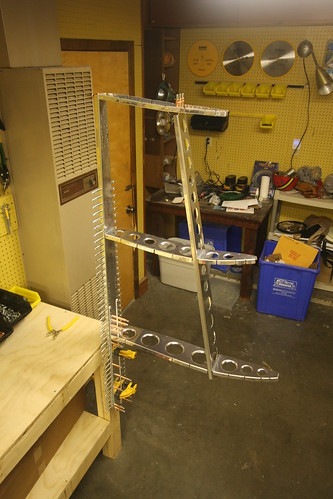
I deburred the rest of the skeleton parts on the scotchbrite wheel and used the pencil tool on the lightening holes. Worked great. Paid special attention to the nose rib points, which I ground down about 3/16" so as not to dimple the skin leading edge when I fold it over the skeleton. Onec that was done, I went ahead and assembled the skeleton with the rear spar clamped to a leg of my workbench:
It was really wobbly. It was really disconcerting how little structural stability this skeleton has with no skin on it. Whereas the rear spar is solid as a rock with those caps and doubler in there, the rest of the parts are just wibbly and I feel like it was going to fold under its own weight. Yikes. Anyway, I thought it would be cool to work on the assembly in its natural upright position, but this came to a rapid end as I needed to final drill those holes on the top rib where it connects to the front spar, and with it clamped to the bench like this, those holes were about six feet off the floor! It made for a cool picture, anyway.
Back on the table, I got the skeleton final drilling out of the way and prepared to put the skin on! First, I had to remove the vinyl from the inside surface. This proved to be harder than I thought it would be. Removing the vinyl from the other parts had been reasonably straightforward. Here I ended up having to wrap the vinyl around a broom handle and rolling that up to pull the coating off. It seemed a lot more sticky than the other parts. Took about 10 minutes just to get the vinyl off that one part. Then, another short bit of instructions that takes forever. "Clecko the skin to the skeleton" translated into about two hours of work. I'm not sure why I had such a hard time with this, but everything I was trying was not working. The hardest part was getting the holes to line up on the middle nose rib. In the end, what worked the best was doing the clecos on one side for everything but the middle nose rib, then turning the assembly over.
Next, I helt a cleco in the hole for the forward-most hole in the skin for the nose rib, then with my other arm I reached under the skin and wiggled the rib back and forth until I got the cleco to drop. It was a giant pain, but it was only required for the five or six rivets on the one side of that nose rib. Once that was done, everything else went into place pretty easily. I finished up with clecoing the skin to the skeleton and called it a night. The result looked something like this:
It's nice to have something that vaguely resembles a plane part on the bench! Also, it was pleasing to note that with the skin on, the stabilizer was rock solid, not the miserable flimsy thing the skeleton had been. First thing tomorrow will be §6.3.4: match-drilling each and every hole in the skin. Unfortunately, after that step, the whole assembly comes apart again for awhile.
11 Oct 2009
Most of the six hours of work that got done today involved things that don't have much visual impact on the vertical stabilizer at all. A lot of dimpling, deburring, and match-drilling parts that were already together. Probably the most visually striking thing that happened was when I removed some strips of vinyl from the front of the VS skin. Bob came by to check out the project so I put him to work helping me get the vinyl strips off.
Aside from the vinyl modification, I got all of the skin holes match drilled and deburred. I also deburred all of the skin/skeleton interface holes on the skeleton. I then started the dimpling. Got all of the skeleton holes dimpled, but gave up on trying to dimple the skin by myself since Bob said he'd help over lunch tomorrow and it'll be a lot easier with two people. The skeleton dimpling required all three of my available dimpling techniques! Most of it was done on the DRDT-2 dimpler (which I love), but a few of the corner holes and holes in the narrow pieces wouldn't work there, so I broke out the pneumatic squeezer and took care of the rest—except for the forward two holes on the top rib, for which even the squeezer wouldn't do. For these, I had to use the pop rivet tool and the nail/dimple die combo. Worked like a champ.
Also took care of countersinking the rear spar/skin interface holes where called out in §6.3.8. With the exception of the skin dimples, the next step is to disassemble the rear spar bits. This will be the last time the spar is together before the parts are primed, so I am likely to hold on doing §6.3.9 until I figure out a few of the customizations I'm going to be adding to this subassembly. In particular, I need to figure out where and how to mount the braided copper grounding straps that will run between the VS and the rudder.
12 Oct 2009
The last day of my four day RV-10 superweekend.
Spent the morning finishing minor tasks like preparing the rudder stops and match-drilling the hinges, etc. When Bob showed up on his lunchbreak, we made quick work of the skin dimpling. The very front hole in the middle rib was not reachable with the DRDT-2 so I had to pop-dimple that one. Otherwise we knocked it out in about 10 minutes and went out for Chinese food.
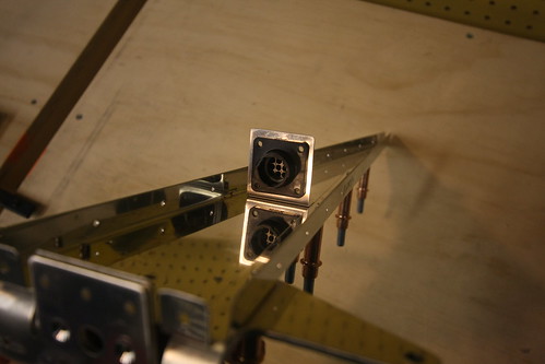
Spent the rest of the day working on some custom parts for my electrical run to the vertical stabilizer fairing. I know I want to mount a camera up there someday, and I have vague notions of someday flying internationally with this thing which means I may need an HF antenna—the top of the tail is a logical place for one end of a longwire antenna on a plane. So I'm running a harness of cables from inside the VS fairing to the base of the VS with circular plastic connectors on each end to facilitate hooking up accessories in the future without having to do a tricky cable run. I also am going to run an empty conduit up to the top in case I want to run an antenna cable but don't want to have lossy connectors in line.
To pull this off, I need doublers at both the top and bottom nose ribs and some way to keep the conduit and cables off the lightening hole edges on the middle nose rib.
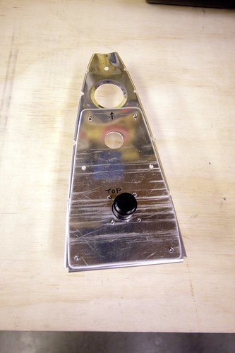
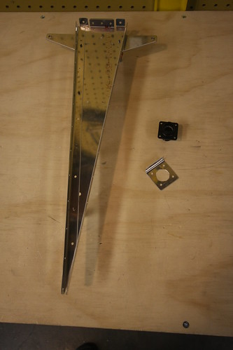
Here is the doubler plate I whipped up for the bottom nose rib. I know it's unnecessarily huge... but whatever it's light. I drilled out holes for the connector and conduit, and rivet holes to attach it to the nose rib and ended up something like this:
For the middle nose rib I found the perfect product—a wire tie bracket made especially for riveting onto lightening holes. How perfect? I just had to drill two small rivet holes in the middle nose rib.
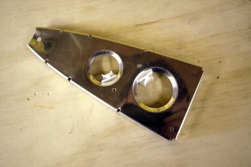
For the top rib I had to make a much more compact doubler since the rib itself is so small. I had concerns about so many holes in such a small piece, but the technical support people at Van's said they didn't forsee any problem with this.
That's about it for today. Only about five hours of actual work. At this point, I am at §6.4.5 which states, simply, "prime the parts." This is going to take some infrastructure preparation so it may be awhile before significant progress occurs on the vertical stab.
17 Oct 2009
The vertical stabilizer parts are all fabricated and awaiting primer, but I need to get some long lumber to make my part prep tanks and I don't have access to my truck this week. So I shelved the VS parts and started on the rudder. No marathon sessions this week, just an hour here and there. Total of about four hours over various lunch breaks and after dinner cleco sessions.
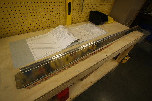
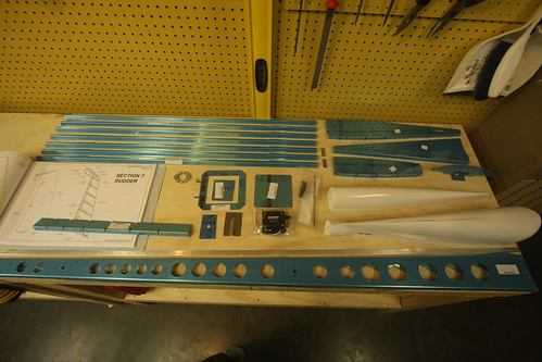
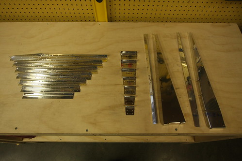
The first step was to lay out all of the rudder parts for a group shot. The only thing missing here is the electrical connectors, wire, and skins.
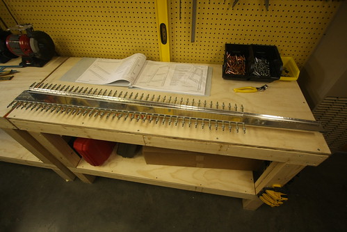
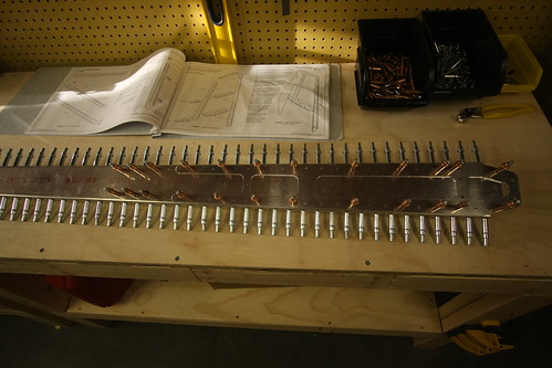
Just like with the vertical stabilizer, the rudder starts out with some bandsaw cuts. In this case, a bunch of smaller pieces are joined together with little tabs for ease of manufacturing. It was a reasonably quick piece of work to turn seven identical pieces of angle aluminum and three other punched sheets into these 25 parts:
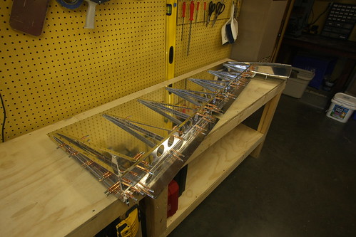
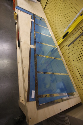
The pieces for the rudder went together astonishingly quickly; it didn't take long at all to get to the point where I was putting skins on for the first time.
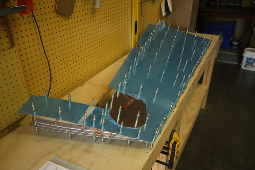
The last thing I did before leaving town for the weekend was put the second skin on in preparation for final drilling.
At this point, I'll probably just finish up with the final drilling and dimpling of all rudder pieces and do all of the priming of both VS and rudder together in one shot to minimize painting overhead.
19 Oct 2009
Over the last two days, I've put in four more hours preparing parts for the rudder. Despite the relatively small number of hours, some significant work was accomplished.
I match drilled all of the holes in the rudder skin, then disassembled the rudder completely and deburred all of the skeleton parts and dimpled the ribs, stiffeners, and spar. I also made some changes for the planned electrical wiring within the rudder.
The plan is to have a wire bundle hanging out the back end of the tailcone beneath the bottom of the lower rudder rib but above the bottom of the lower rudder fairing. A hole will be made in the lower fairing that will allow this cable to enter the fairing during normal operation. The wire will connect to a circular plastic connector attached to the bottom of the lower rudder rib, and from there the cables will split into two groups. The first group will just connect to the tail light at the aft end of the fairing. The second group will pass through a snap bushing in the lower rib and then travel up through three of the stiffeners to the area where the rudder trim modification will eventually be made.
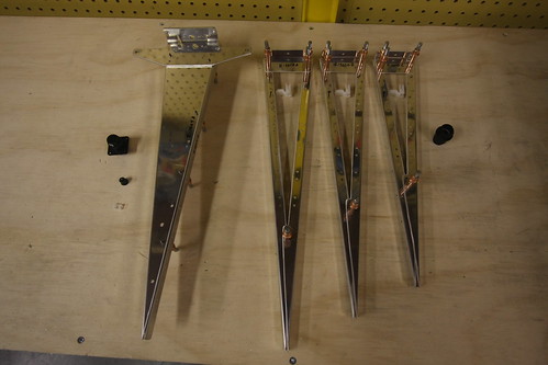
For the time being, the wire bundle will just end in another CPC between the C and D stiffeners. I'll make the cuts for the rudder trim after the rudder has been riveted together. In order to safely pass the wires through the triangular holes in the stiffeners, I drilled out one of the unused holes in each of the left side stiffeners to which I plan to rivet some of the lightening hole wire tie attach brackets. These should keep the wires out of contact with the metal. Thus, the modifications to the three stiffeners were composed simply of final drilling three holes.
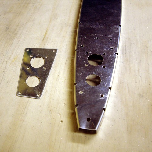
The lower rib was a bit more complex. First I fabricated a small angle flange to attach the CPC to.
This, in turn, will get riveted to the bottom side of the lower rib.
Finally, a 3/8" hole was drilled aft of the CPC flange in the lower rib for the snap bushing through which the trim servo wires will pass. That's it for parts fabrication for the rudder wiring. I disassembled the lower rib and modified flanges, deburred everything, and dimpled them where appropriate.
All that remains before priming of the rudder is to make the bend at the trailing edges of the skins, deburr the skins, and dimple the skins.
20 Oct 2009
Nothing momentous happened today; spent about an hour deburring both sides of both rudder skins. Need to figure out the right way to make the bend in the trailing edge before I proceed to dimpling.
29 Oct 2009
A bunch of random things have occurred in the last week. After reading up on other builders websites, I determined that I wouldn't be making the bend in the trailing edge of the rudder at all. I'll be using the angle iron backrivet technique and tank sealant to ensure a good bond at the trailing edge.
Making this decision cleared me to finish up the rudder skins. I removed the vinyl coating from the rivet lines and Bob assisted with the dimpling of all the holes. The next step on the skins will be to scuff the inner surface, clean it, and then prime it.
I spent a lot of time thinking about how to do bond straps between the rudder and vertical stab. I was unable to find appropriate ring terminals, bolts, washers, and nuts in aluminum... so I've decided to use passivated cadmium-plated steel hardware instead and hope for the best. I ordered some candidate pieces from Aircraft Spruce and they look like they might work. I also ordered hardware for making the vertical stabilizer and lower rudder fairings removable via nutplates. Unfortunately I based my parts decisions here on another builder's website who had a typo in their part numbers! I ordered thirty K1000-6 nutplates instead of K1000-06 nutplates without checking the bolt size vs. nutplate size. That's a $50 oops! Reordered the correct nutplates from Van's. They'll be here long before I'm ready for them. If anyone needs any of the huge K1000-6 nutplates... let me know.
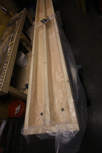
The other major accomplishment of this week was building the dunk tank for doing alumiprep and alodine chemistry on the long thin parts of the aircraft. I didn't want to have to build more than one of these, so I made it really long to accomodate the longest pieces of the airplane. Right now, the longest parts I know of are the horizontal stabilizer spars, which come in at about 11'6" each. I bought three twelve foot 2x4s and made a simple double-trough frame out of them. I used the plywood from the empennage delivery crate for the bottom of the troughs, and a four foot spare piece of 2x4 from the workbench assembly for the end caps. Drilled drain holes in one end and fashioned a couple of 2x4 blocks to allow for length customization, saving on chemical volume when working on parts shorter than the horizontal stabilizer spars.
Above is a picture of the finished dunk tank with the length blocks set at about six feet, just longer than the longest parts in both the rudder and vertical stabilizer. I then lined the active side of the tank with 4 mil plastic sheet and poked it down through the drain holes. I used a staple gun to temporarily keep the sheet in place. The dunk tank is ready to go! More pictures here.
The last thing I did was to rig up hooks and line for allowing the parts to air dry after the alumiprep and alodine washes are complete. Currently all of the parts for both the vertical stabilizer and rudder and hanging in the shop. The only thing I'm missing before I proceed with the chemistry is buckets to reclaim the used water and chemicals. Should be able to pick those up at the local hardware store. Then, it'll be time for SCIENCE!
31 Oct 2009
Got three sealable five-gallon buckets this morning, one for alodine, one for alumiprep, and one for distilled water. The Alodine comes by the gallon and gets mixed 1:2 with water, for a total of three gallons of solution. The Alumiprep also comes by the gallon and gets mixed 1:3 with water, for four gallons of solution. I pre-mixed these and labeled their respective buckets.
With the adjustable blocks in my dunk tank set at just over five feet (the length of the rudder spar), and each trough being six inches wide, three gallons was enough for an almost two inch deep pool of Alodine. I only used about three gallons of the Alumiprep as well.
The process of immersing the parts in each bath and then drying went surprisingly quickly. I was able to prep and alodine all of the parts for both the vertical stabilizer and rudder in about two hours including setup and cleanup. Also, this was my first time figuring out how everything would work, so I took a lot longer on some steps than I will require when I do this again for the horizontal stabilizer.
All of the parts now have that great golden finish to them and are ready for priming.
| <-- September 2009 | November 2009 --> |